Seeed Technology SenseCAP LoRaWAN 868 User manual


User Manual
© 2008-2019 Seeed Technology Co., Ltd. All rights reserved. www.seeed.cc
2/ 34
Table of Contents
1Product Introduction.............................................................................................................................. 3
2Key Parameters of the Sensor Node....................................................................................................5
Introduction of Key Parameters .................................................................................................5
Get Device EUI, App EUI and Key............................................................................................. 5
3Connect to Gateway and Servers.........................................................................................................7
Configuration Overview..............................................................................................................7
Connect to the SenseCAP Gateway (Recommend Product).................................................... 9
Connect to a Standard LoRaWAN Gateway.............................................................................11
3.3.1 Power On .......................................................................................................................11
3.3.2 Sensor Node Working Status........................................................................................12
3.3.3 Connect to the Gateway (LPS8) and TTN Server ........................................................ 12
4How to Modify the Key Parameters ....................................................................................................20
Preparation...............................................................................................................................20
Modify the Device EUI, App EUI & Key and Data interval.......................................................22
Modify the Sub-band................................................................................................................ 24
5Decoding .............................................................................................................................................25
Packet Parsing......................................................................................................................... 26
Battery Information...................................................................................................................29
6Device Installation............................................................................................................................... 31
Installing Sensor Node.............................................................................................................31
6.1.1 Installing the Sensor Node Bracket .............................................................................. 31
6.1.2 Installing Sensor Nodes ................................................................................................32
6.1.3 Dos and Don’ts in Installing Sensor Probes .................................................................33
7Trouble Shooting.................................................................................................................................34
Sensor Node not join the network, how to do?........................................................................ 34
Why is the new sensor’s battery not 100%?............................................................................34
Why can't I get into configuration mode with the USB to TTL serial tool?...............................34
Support..................................................................................................................................... 34

User Manual
© 2008-2019 Seeed Technology Co., Ltd. All rights reserved. www.seeed.cc
3/ 34
1Product Introduction
SenseCAP is an industrial wireless sensor network that integrates easy-to-deploy hardware and data API
services, enabling low-power, long-distance environmental data collection.
SenseCAP LoRaWAN products include LoRaWAN Gateways and Sensor Nodes. Based on the LoRaWAN
protocol, it can realize one-to-many, long-distance networking and bilateral communication. The LoRaWAN
Gateway supports Ethernet and 4G. The Sensor Node is powered by a high-capacity battery that lasts up
to 3 years (if uploading data once every hour). It also supports hot-swap, making it easy for maintenance
and upgrading.
It is recommended that you use the SenseCAP LoRaWAN Gateway. You can have out-of-the-box
experiences without complex operations. We also provide the SenseCAP Portal, where you can view the
data and manage the device when the device is powered on, and you can use the API for integrated
development. SenseCAP LoRaWAN Gateway can use SenseCAP Server, The Things Network Server,
and Chirp Stack Server to build your applications.
SenseCAP LoRaWAN Sensor Nodes can work with third-party standard LoRaWAN gateways. For users
who already have an existing LoRaWAN gateway, please kindly refer to this tutorial about connecting
SenseCAP Sensor Nodes with your gateway.

User Manual
© 2008-2019 Seeed Technology Co., Ltd. All rights reserved. www.seeed.cc
5/ 34
2Key Parameters of the Sensor Node
Introduction of Key Parameters
Using the LoRaWAN protocol generally involves the following parameters.
Parameters
Description
Device EUI
Unique identification of device, one of the network join parameters.
Device Code
For device binding and API call.
App EUI
Unique identification of application, one of the network join parameters.
App Key
Application key, one of the network join parameters.
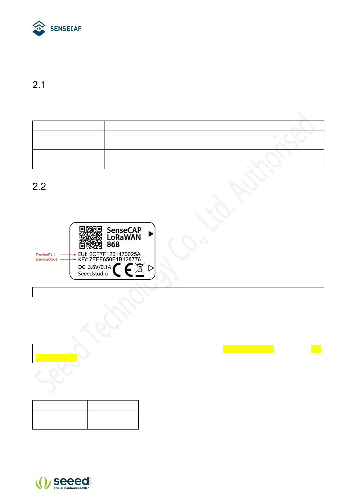
Get Device EUI, App EUI and Key
(1) Device EUI and Device Code is on the SenseCAP product label.
Tips: Device Code is not the App Key!
(2) SenseCAP Sensor Node’s App EUI and App Key have been flashed into the device by Seeed. Use
HTTP API to get App EUI and App Key. You can use a browser to issue an HTTP GET request.
Curl:
https://sensecap.seeed.cc/makerapi/device/view_device_info?nodeEui=2CF7F12014700297&deviceCode=34B
F25920A4EFBF4
In the API, replace the Device EUI and device Code with your own Device EUI and Device Code
respectively. And you will get the following response:
dev_eui
Device EUI
app_eui
App EUI
app_key
App Key
User Manual
© 2008-2019 Seeed Technology Co., Ltd. All rights reserved. www.seeed.cc
6/ 34
{
"code": "0",
"data": {
"nodeEui": "2CF7F12014700297",
"deviceCode": "34BF25920A4EFBF4",
"lorawanInformation": {
"dev_eui": "2CF7F12014700297",
"app_eui": "8000000000000006",
"app_key": "6FD0EF47CBC6E00F1921A08C2E94E8E5"
}
},
"time": 0.019
}
Tips: The SenseCAP LoRaWAN Sensor can modify to EUI and Key. Please refer to the following
sections.

User Manual
© 2008-2019 Seeed Technology Co., Ltd. All rights reserved. www.seeed.cc
7/ 34
3 Connect to Gateway and Servers.
Configuration Overview
Device Parameters
LoRaWAN MAC version
1.0.2
LoRaWAN Regional Parameters revision
B
Join Type
OTAA
Device EUI
Refer to section 2 for details.
App EUI
Refer to section 2 for details.
App Key
Refer to section 2 for details.
Frequency Plans
EU868
(LoRa-S-868-
XXX-XX)
Uplink:
868.1 - SF7BW125 to SF12BW125
868.3 - SF7BW125 to SF12BW125 and SF7BW250
868.5 - SF7BW125 to SF12BW125
867.1 - SF7BW125 to SF12BW125
867.3 - SF7BW125 to SF12BW125
867.5 - SF7BW125 to SF12BW125
867.7 - SF7BW125 to SF12BW125
867.9 - SF7BW125 to SF12BW125
868.8 – FSK
Downlink:
Uplink channels 1-9 (RX1)
869.525 - SF9BW125 (RX2 downlink only)
US915
(LoRa-S-915-
XXX-XX)
902.3
903.9
905.5
907.1
908.7
910.3
911.9
913.5
125kHz
DR0 to
DR3
902.5
904.1
905.7
907.3
908.9
910.5
912.1
913.7
902.7
904.3
905.9
907.5
909.1
910.7
912.3
913.9
902.9
904.5
906.1
907.7
909.3
910.9
912.5
914.1
903.1
904.7
906.3
907.9
909.5
911.1
912.7
914.3
903.3
904.9
906.5
908.1
909.7
911.3
912.9
914.5
903.5
905.1
906.7
908.3
909.9
911.5
913.1
914.7
903.7
905.3
906.9
908.5
910.1
911.7
913.3
914.9
Channel
0 to 7
Channel
8 to 15
Channel
16 to 23
Channel
24 to 31
Channel
32 to 39
Channel
40 to 47
Channel
48 to 55
Channel
56 to 63
User Manual
© 2008-2019 Seeed Technology Co., Ltd. All rights reserved. www.seeed.cc
8/ 34
903
904.6
906.2
907.8
909.4
911
912.6
914.2
Channel
64 to 71
500kHz
DR4
Sub-band
1
Sub-band
2
Sub-band
3
Sub-band
4
Sub-band
5
Sub-band
6
Sub-band
7
Sub-band
8
Downlink:
923.3 - SF7BW500 to SF12BW500
923.9 - SF7BW500 to SF12BW500
924.5 - SF7BW500 to SF12BW500
925.1 - SF7BW500 to SF12BW500
925.7 - SF7BW500 to SF12BW500
926.3 - SF7BW500 to SF12BW500
926.9 - SF7BW500 to SF12BW500
927.5 - SF7BW500 to SF12BW500


User Manual
© 2008-2019 Seeed Technology Co., Ltd. All rights reserved. www.seeed.cc
10 / 34
Step3: Log on to the SenseCAP Portal to view the data.
Step4: Install the gateway and sensors.
Refer to SenseCAP LoRaWAN Gateway for more details:
https://www.seeedstudio.com/LoRaWAN-Gateway-EU868-p-4305.html

User Manual
© 2008-2019 Seeed Technology Co., Ltd. All rights reserved. www.seeed.cc
11 / 34
Connect to a Standard LoRaWAN Gateway
SenseCAP Sensor Nodes support standard LoRaWAN 1.0.2 protocol, making it possible to connect to
standard LoRaWAN gateways and servers.
3.3.1 Power On
The power switch is hidden inside the device. Open the device and turn on the power before installing the
sensors. Here is the step-by-step instruction:
1) Loosen the Sensor Probe by turning the cap counterclockwise. Use the white cap opener to make this
process easier. The image below uses TH Sensor as an example and applies to all other SenseCAP
sensors.
2) After opening the device, turn the switch to “ON”, and the LED on the lower right corner will flash,
indicating that the power is on. Wait for about 10 seconds, then the LED will flash quickly for 2 seconds,
indicating that the device is connected to the network.

User Manual
© 2008-2019 Seeed Technology Co., Ltd. All rights reserved. www.seeed.cc
12 / 34
3) After the device is connected to the network, connect the Sensor Probe back with the Sensor Node
Controller by turning it clockwise. Please note that the labels on both parts should be aligned as shown
in the image below, otherwise the two parts will not be attached to function properly and data will not
be uploaded.
3.3.2 Sensor Node Working Status
You can refer to the LED indicator for the Sensor Node for its working status. Please see the status
explanations in the image below:
3.3.3 Connect to the Gateway (LPS8) and TTN Server
Typically, The LoRaWAN gateway needs to set the server address and uplink and downlink channel
parameters for the end device. Refer to the gateway user manual to configure the server. Here, a common
LoRaWAN Gateway (LPS8-915MHz) is taken as an example to explain how to configure the
communication parameters of the Sensor Node.
User Manual
© 2008-2019 Seeed Technology Co., Ltd. All rights reserved. www.seeed.cc
13 / 34
You can learn more about LPS8 Gateway:
https://www.seeedstudio.com/LPS8-Indoor-LoRaWAN-Gateway-Included-SX1308-LoRa-Concentrator-p-
4251.html
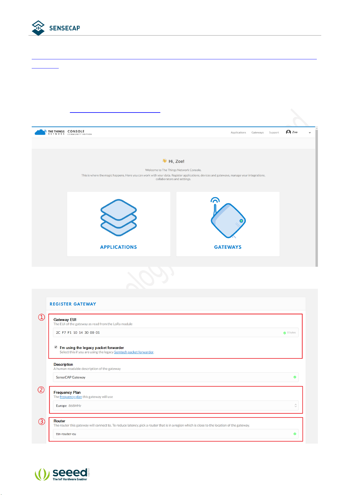
1) Gateway Registration on TTN
TTN website: https://www.thethingsnetwork.org
Follow the instruction to create your account, and access “Console”.
Register Gateway:
①Gateway EUI: View the labels on the gateway.

User Manual
© 2008-2019 Seeed Technology Co., Ltd. All rights reserved. www.seeed.cc
14 / 34
Select ‘I’m using the legacy packet forwarder’.
②Frequency Plan: View the labels on the gateway.
③Router: Select the router that is right for you.
④Register.
Gateway Status displays connected, indicating successful registration.
2) Create an Application
TTN console → Application → Add application
①Application ID: Enter a unique name.
②Description: Enter a description.
③Handler registration: Select the same handler as the gateway router.
④Add application.


User Manual
© 2008-2019 Seeed Technology Co., Ltd. All rights reserved. www.seeed.cc
16 / 34
3) Sensor Node Registration on TTN
Application → Devices → register device
①Device ID: Enter a unique name.
②Device EUI: Enter the node’s Device EUI that you got in the previous step.
③App Key: Enter the node’s App Key that you got in the previous step.
④App EUI: Select the node’s App EUI.
⑤Register.


User Manual
© 2008-2019 Seeed Technology Co., Ltd. All rights reserved. www.seeed.cc
20 / 34
4How to Modify the Key Parameters
Preparation
Tools
USB to TTL Serial Tool *1
Software
SenseCAP Node Configuration Tool
Windows: SenseCAP-Node-Configuration-Tool-x.x.x.exe
Mac: SenseCAP-Node-Configuration-Tool-x.x.x.dmg
Download: https://github.com/Seeed-Solution/SenseCAP-Node-Configuration-
Tool/releases/tag/v1.0.3
Connect serial ports (as shown in the image below), turn on the power, launch the serial port monitoring tool on
your computer.
USB to TTL Serial Tool
Sensor Node
RX
TX
TX
RX
GND
GND
Baud Rates
115200
Install the SenseCAP Node Configuration Tool.
Table of contents
Popular Accessories manuals by other brands


PCB Piezotronics
PCB Piezotronics 356M57/NC Installation and operating manual

Saimo
Saimo 6105 Installation, operating and service manual

IFM
IFM LMT0 A Series operating instructions

Philips
Philips 373414816 Specifications

Focusrite
Focusrite Forte user guide

Hella
Hella C2 Installation instructions and instructions for use


