Installation Instructions and Instructions for Use
Subject to technical modifications – Date of issue January/2023 5
CE marking
The HELLA cassette awning C2 is in compliance with the declaration of performance
according to the Construction Products Regulation; if the unit is operated with a motor drive
it is additionally in compliance with the Machinery Directive and the Guideline for
Electromagnetic Compatibility; in case of proper use, the awning corresponds to the basic
requirements of the harmonised standard EN 13561. The respective declarations are
deposited with the manufacturers.
The CE identification applies for the delivery status of the product. Exceptions and
specifications regarding the wind resistance of the installed awning are given in the
respective product documentations. The product mounted meets the requirements of the
specified standard only, if
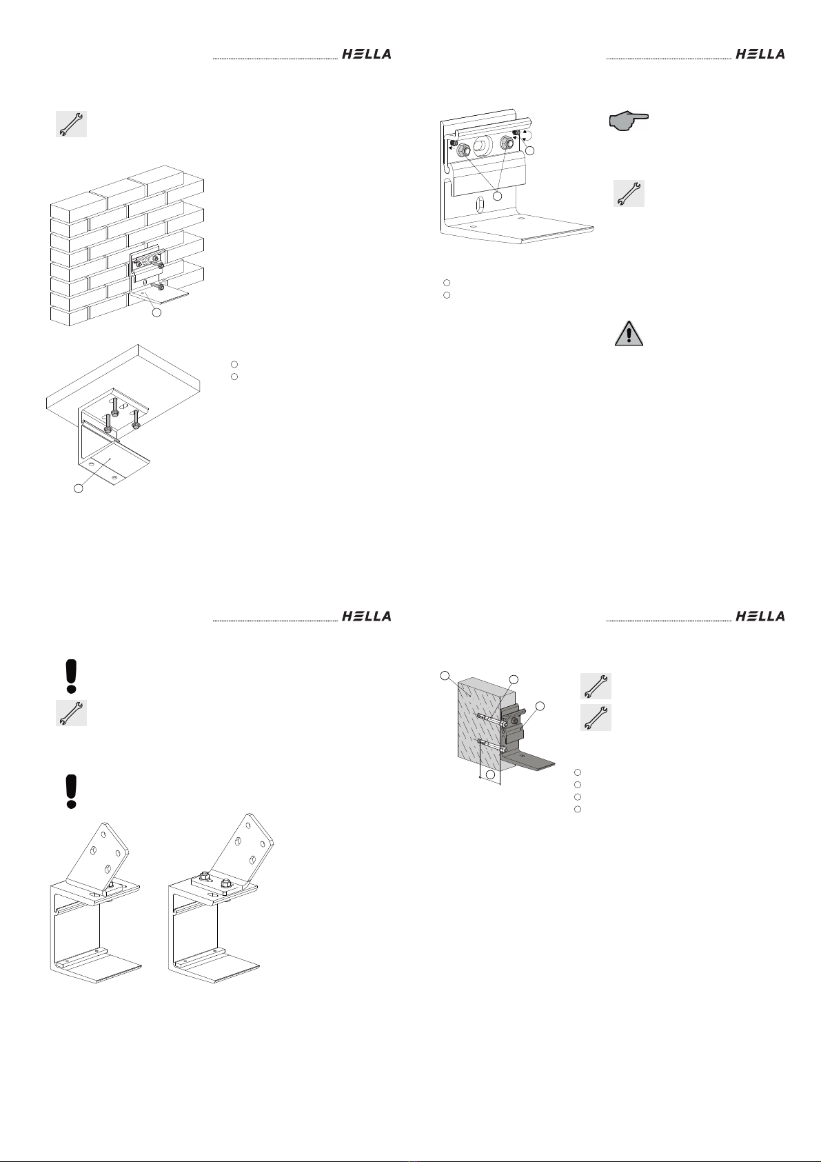
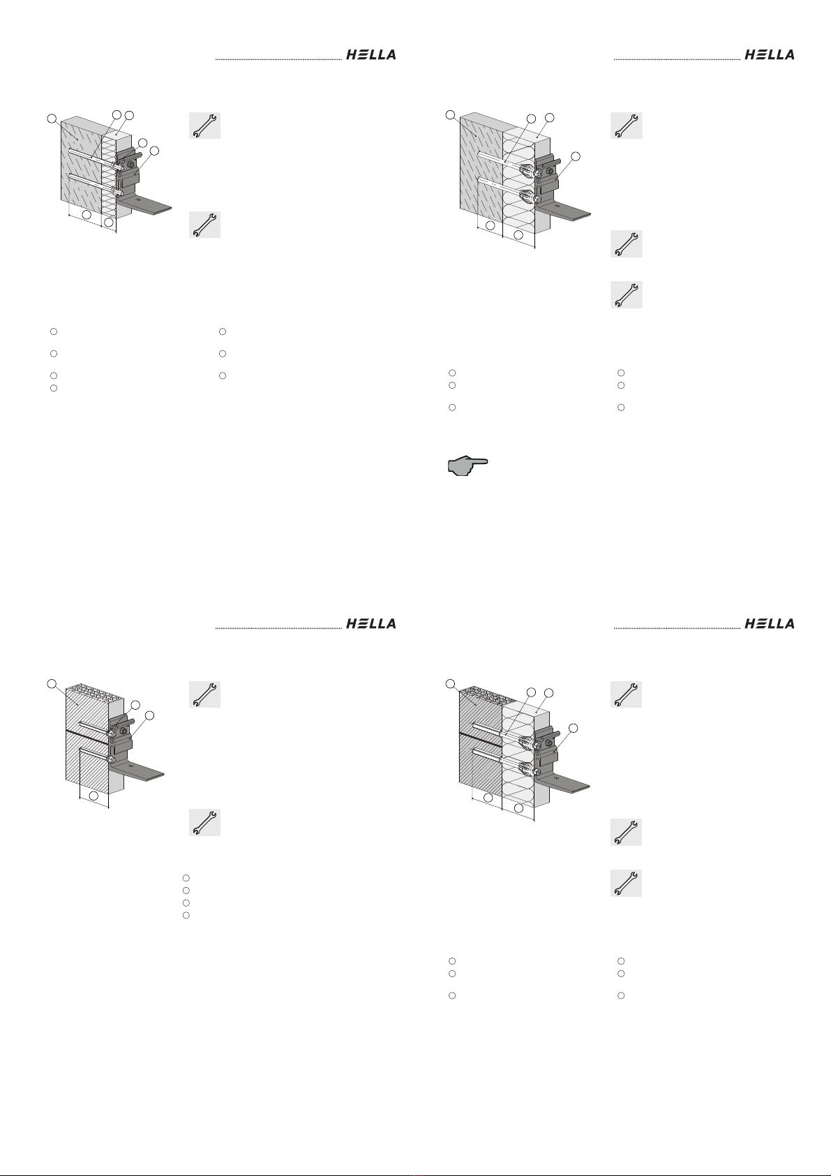
the awning is installed with the recommended type and number of brackets.
during installation the information and instructions given in these instructions as well
as the information and instructions of the manufacturers of the screws / dowels have
been observed,
the product is installed with the recommended type and number of fasteners /
screws.
No changes, rebuildings or extensions, with the exception of those described in these
instructions, are allowed with this product. The fixed CE-label expires with any change,
rebuilding or extension.
HELLA Sonnen- und Wetterschutztechnik GmbH
A-9913 Abfaltersbach, Nr. 125
23
LE-GGAM-01-002
EN 13561:2004+A1:2008
Cassette awning
C2
Exterior textile sun protection
Wind resistance: class 1
Installation Instructions and Instructions for Use
6 Subject to technical modifications – Date of issue January/2023
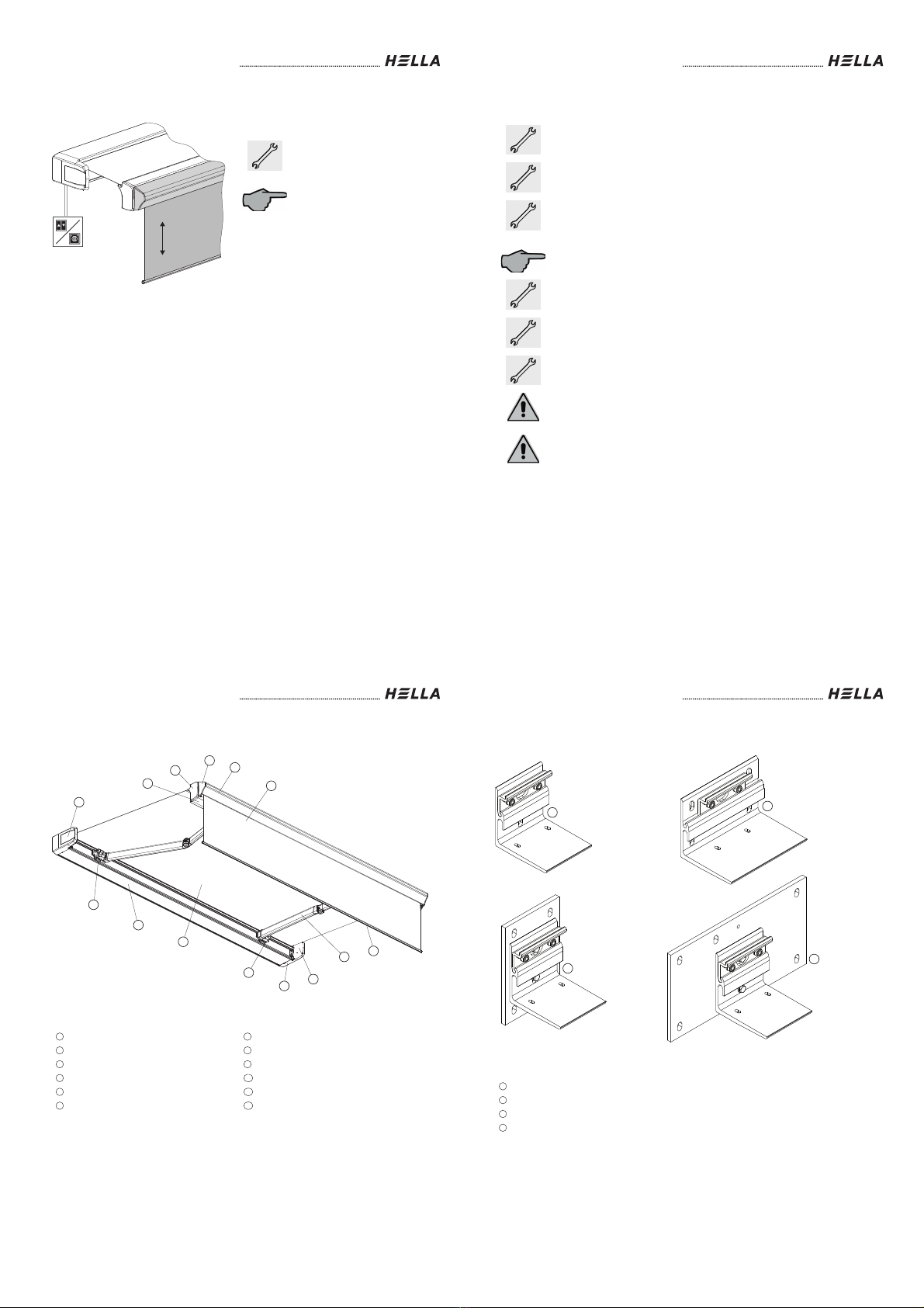
Safety instructions
These installation instructions refer to prefabricated elements, that (1) for
100% are made from parts, which are defined by us, and (2) which are
made in manufacturing processes, which are defined by us too; in all other
cases we do not provide any guarantee!
The safety instructions as well as the appropriate instructions must be read
carefully before installation and use. In case of non-observance of the
directions and information given in these instructions and in case of
improper installation and operation or unintended use, the manufacturer
shall not accept any warranty claims concerning any damage to the
product. In these cases, the liability for consequential damage to any parts
or persons is ruled out as well.
- Follow the described installation steps and pay attention to
recommendations and notes.
- Keep these instructions in a safe place.
- All installation and removal works, as well as maintenance and repair
works are only allowed to be carried out by authorised and qualified
specialist staff.
- If switching, automatic or radio control devices are used to operate the
units, the information given in the enclosed instructions of the
manufacturer must be observed.
- During operation do not put your hand into or touch movable parts.
- Ensure that clothing or body parts cannot get caught on the unit.
- Observe the regulations for prevention of accidents of the employer's
liability insurance association!
- Before operation check the unit for visible damage. If the unit is
damaged, it should not be used; please consult authorized specialist
staff immediately.
- Risk of injury and accident due to the weight of the product!
- Take safety measures against the danger of squashing, especially when
operating the unit with automatic devices.
- Place the operating switch within sight of the unit, but not near any of the
moving parts.
- Never let children play with the unit.
A sun protection device with electric drive cannot be retracted without
current. We therefore recommend the use of an emergency power
generating unit or a motor with an emergency crank handle, especially in
regions with frequent power failures.
Danger of suffocation!
Ensure that the foil cannot get into the hands of children. Keep the foil in a
safe place.
Installation Instructions and Instructions for Use
Subject to technical modifications – Date of issue January/2023 7
Safety instructions
Attention! Risk of injury or danger to life due to an electric shock!
- Set-up, examination, commissioning and error correction of the unit must
only be performed by authorised or trained expert staff (as per VDE
0100).
- Switch off the current to the connecting lines when working at the unit.
There is danger to life! Take safety precautions against unintentional
switching on!
- Check the electrical wires regularly for damage. Do not use the unit if
any damage is found.
- Our electrically driven units are in accordance with the regulations for
power plants acc. to VDE 0100. We cannot guarantee for the operational
reliability of the unit with non-approved modifications.
- White motor cables are not UV-resistant and must therefore be routed in
empty conduits, cable ducts, or similar.
- The enclosed installation instructions of the electrical devices supplied
must be observed.
Units with motor drive:
The drives used are operated with a voltage of AC 230V/50Hz. Please
check the power supply provided by your utility company before connecting.
Any other voltage can destroy the drives.
Danger of squashing
To avoid at the best the danger of squashing in the area of movable parts,
such as roller tube, cassette, folding arms, front rail etc., especially when
automatic devices are used or when the unit is for example operated
automatically by a wind controller or rain sensor, it is mandatory that the
awning is installed in a height of at least 2,5 m or above, measured from the
floor or a permanent access way.
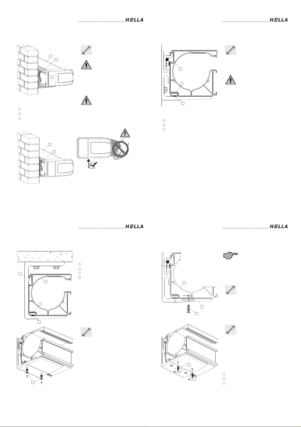
Hereby it must be observed, that a distance of at least 0.40 m between the
front rail and a fixed object is ensured, if the front rail, due to the inclination
of the awning, goes below a height of 2.5 m, measured from the floor or a
permanent access way.
If such an installation is due to the local situation not possible , the client
has to take appropriate safety measures, such as a cover or placing the
operating switch (touch contact switch) within sight of the awning.
Installation Instructions and Instructions for Use
8 Subject to technical modifications – Date of issue January/2023
Safety instructions
If it is necessary to lift the awning via ropes at a higher altitude, the awning
must
- be removed out of the packaging.
- be tied to the pull ropes in such a way, that a slipping out of the awning is
prevented,
- lifted evenly in a horizontal position.
The same applies for the removal of the awning.
It is not allowed that climbing aids are leaned against or fixed to the awning.
They must have a stable base and provide a firm support. Only use
climbing aids with an appropriate carrying capacity.
When working at higher heights, there is risk of falling. Please make sure
that suitable fall protection devices are used.
Awnings are only allowed to be used for the purpose specified in the
instructions for use. Changes, such as extensions or rebuildings, that are
not provided by the manufacturer, are only allowed to be carried out with
the manufacturer’s written approval.
Additional loadings such as objects that are sticked to the awning or cable
tensionings can damage the awning or lead to its crashing, and are
therefore not allowed.