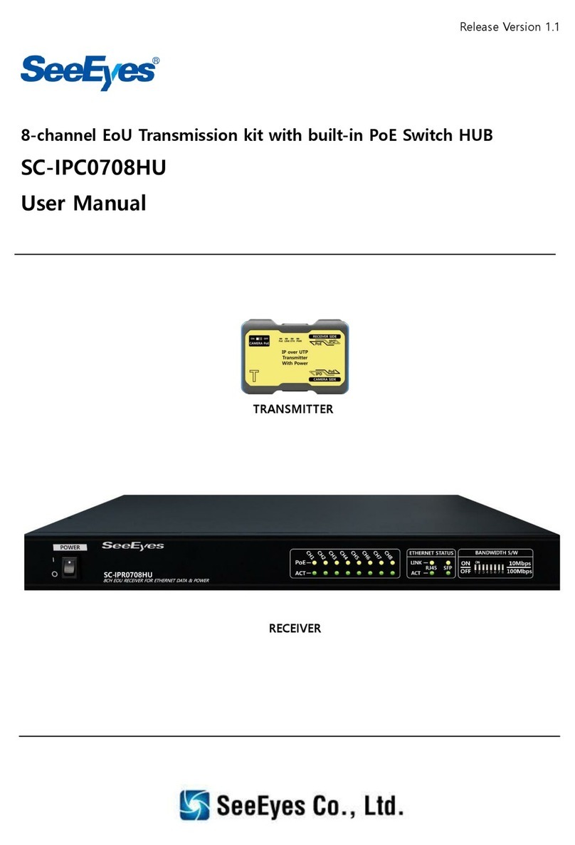
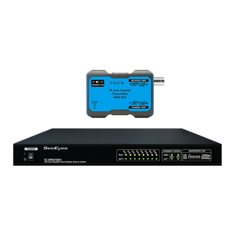
SeeEyes SC-IPT3001E User manual

Release Version 1.8
1Channel IP over Coaxial Transmission Solution
SC-IPT3001E, SC-IPR3001E
User’s Manual
SC-IPR3001E
(1CH Receiver)
SC-IPT3001E
(1CH Transmitter)

Release Version 1.8
1
Precaution and Safety Guidelines
The content of this guideline is to protect the safety of users and prevent property damage.
Be sure to read this user’s manual thoroughly and use the device correctly.
Warning (If you do not keep any of the below guidelines, you may get seriously injured or
cause somebody’s death.)
■Be sure to install the product after unplugging power cord. Also, do not use several
power plugs at the same time.
- It may cause abnormal heat, fire and electric shock.
■Do not leave the device at any place that water falls or splashes. Also, do not put anything
full of water such as a flower vase on the device.
- It may cause malfunction or fire if liquid goes into the device.
■Do not bend the power cord by excessive force. Make sure the power cord is not crushed by
heavy things.
- It may cause fire.
■Do not open the lid arbitrarily as this device has high voltage part inside. Never disassemble,
repair or modify it.
- By abnormal working, it may cause fire, electric shock and personal injury.
■Do not install this product in places with high humidity, dust, or soot.
- It may cause electric shock and fire.
■Do not tug at the power cord section or unplug the power plug with wet hands. If the power
cord is loose, do not plug in.
- There may be a risk of fire and electric shock.
■Always keep the location of the appliance clean during or after installation to prevent dust.
Especially when cleaning the device, wipe it with dry towel and do not use water, thinner or
organic solvent.
- It may damage the case of this device, and cause malfunction or electric shock.
■Keep the device in a cool place where doesn’t let direct sunlight. Keep it at a proper
temperature and avoid heating appliances like candle or heater. Also, keep the equipment or
tools away from places where people come and go.
- It may cause fire.
■Pay attention to possible hazards in the workplace, such as wet floor, ungrounded power
extension cables, old power cords and a lack of safety earth. Consult your place of purchase or
professional if problems arise.
- It may cause fire and electric shock.
■Concerning the input voltage for operating this device, a voltage range must be within 10%
of rated voltage, and the power outlet must be grounded. Also, do not use a heat source such
as a hair dryer, iron and refrigerator to the same power unit.
- It may cause abnormal heat, fire and electric shock.

Release Version 1.8
2
Caution (If you do not keep any of the below guidelines, you may get injured or suffer
property loss.)
■Proper ambient temperature and humidity are recommended.
- Avoid extremely high temperatures(over 50°C) or low(below -10°C), and humid conditions.
■Install in well ventilated place, and avoid direct sunlight or heat appliance.
■Be sure to plug the power cord with grounded outlet.
- There is a risk of electrical shock and personal injury.
■Do not use this device in close proximity to a device that produces strong waves such as
radio set(TRANCEIVER, Walkie-talkie, etc.) or repeater. It may affect the video signal, or cause
disorders such as noise or crack on the screen.
■Transmission distance may vary depending on the type of coaxial and UTP cable.
■Disconnect the power plug with care during thunder and lightning.
■When connecting cables, install as “U” shape in order to prevent rainwater/dew/fog from
getting into the product.
■Refer to the user’s manual for problems or questions besides the above. Contact our service
center if you need assistance from a professional technician.
■When you extend or terminate coaxial cable, it should be connected in the following way.
- BNC-M(Male) - BNC-JJ - BNC-M(Male): BNC Connector
■Make the joint part of the cables insulated completely not to expose the metal parts.
■When using the product in outdoor, we recommend to use STP(Shield Twisted Pair) because
UTP(Unshielded Twisted Pair) Cable is for indoor use.
- Use UTP cable above than standard CAT.5e.
■Make sure to read this user’s manual thoroughly since this product has PoC function that
might generate a problem such as malfunction when connected with other products.
■Configure in separate for general network use (Internet, indoor, etc.) and CCTV usage.
- It might be the cause of problem.
■Be careful not to change the Network cable connection.
- Refer to the Cable Connection way below.
Network Cable Diagram
TIA / EIA 568B Type
Pin No.
Color
Func.
1
White
Orange
TX+
2
Orange
TX-
3
White
Green
RX+
4
Blue
PWR+
5
White
Blue
PWR+
6
Green
RX-
7
White
Brown
PWR-
8
Brown
PWR-

Release Version 1.8
3
1. Introduction
1-1. Overview
SC-IPC3001E is a 1CH IP PoC transmission unit composed of SC-IPT3001E (Transmitter) and
SC-IPR3001E (Receiver). With PoC function, this product supplies power to Transmitter and camera
and power construction is unnecessary. In addition, since only coaxial cable construction is needed,
construction period is shortened and installation cost is reduced.
Also, coaxial cable laid between the transmitter and receiver enables long-distance transmission (up
to 2,600m over RG-6 cable) of Ethernet data, which compensates for the disadvantage of short
network transmission distance.
1-2. Features
•Supply power to IP camera (supports PoE Type B / Max. 30W)
•Transmission bandwidth: PHY (Physical Layer Speed) Rate : Up to 200 Mbps
•Transmit Max. 1,400m power + digital data (over RG-6 coaxial cable)
•Transmit Max. 2,600m digital data (over RG-6 coaxial cable)
•Auto MDI/MDIX function
•Supply stable power by auto cable checking function.
•PoE ON/OFF function for Transmitter connected to camera
•Built-in surge protection circuit
2. Components
2-1. SC-IPT3001E (Transmitter)
SC-IPT3001E
Bracket
RJ-45 Cable
User’s Manual
2-2. SC-IPR3001E (Receiver)
SC-IPR3001E
DC 48V Adapter
Power Cord
Bracket
User’s Manual

Release Version 1.8
4
3. Product Parts and Functions
3-1. SC-IPT3001E (Transmitter)
①CAMERA PoE: Switch to set power supply to PoE IP camera
※In case of connecting PoE IP camera, set CAMERA PoE switch as ON.
※The factory setting for the PoE switch is ON.
※In case of connecting non-PoE IP camera, set CAMERA PoE switch as OFF.
②LED Indicator
Name
Color
Status
Description
PWR
Red
On
Power On / Pairing completed
Flashing
Under pairing
Off
Power Off
ETH
Green
Flashing
Ethernet connected
Off
Ethernet not connected
LINK
Green
On
Connected to Receiver
Off
Not connected to Receiver
PoE
Red
On
Supplying PoE to IP camera
Flashing(0.6 seconds cycle)
Flashing(0.2 seconds cycle)
IP camera current input standby
IP camera overcurrent
OFF
Not supplying PoE to IP camera
※When turning the product on, the LED turns on sequentially first and the product is operated.
③RECEIVER SIDE: Port to connect Receiver and output video
④CAMERA SIDE: Port to connect IP camera
①
③
④
②

Release Version 1.8
5
3-2. SC-IPR3001E (Receiver)
①NVR SIDE: Port to connect NVR or PoE Hub
②DC 48~56V IN: Port to input DC adapter (48V or 56V) power
③TRANSMITTER SIDE: Port to connect Transmitter and input video
④LED Indicator
Name
Color
Status
Description
PWR
Red
On
Power On / Pairing completed
Flashing
Power output / Under pairing / Coaxial cable not connected
Off
Power Off
ETH
Green
Flashing
Ethernet connected in normal
Off
Ethernet not connected
LINK
Green
On
Connected to Transmitter
Off
Not connected to Transmitter
PoC
Red
On
PoC power On
Flashing
Over consumption for Coaxial cable
Off
PoC power Off
※When turning the product on, the LED turns on sequentially first and the product is operated.
⑤FUNC Button: Function to pair and operate Transmitter and Receiver each other
<How to Use FUNC Button>
※In case of first installation or replacement of Transmitter or Receiver, use this button for
communication between Transmitter and Receiver
※Press FUNC button on the Receiver about 3 seconds (The PWR LED blinks)
※Wait about 1 minute until the Transmitter and Receiver is connected.
※After the LED’s LINK is On, the connection between Transmitter and Receiver is completed.
★In case of initial input, the product retries by own until the pairing is completed even though
the connection is failed.
★Press the pairing(FUNC) button again if necessary depending on the environment.
④
④
①
③
②
⑤

Release Version 1.8
6
4. Daisy-Chain Connection
4-1. Overview
Up to 3 transmitters can be configured with 1 receiver for Daisy-chain connection.
4-2. How to Use Daisy-Chain Connection
<How to configure Daisy-Chain>
a) Perform Pairing by connecting 1 Tx(Transmitter) to Rx(Receiver).
b) Connect additional Tx to Paired Tx with t T-connector, etc.
c) In the OFF state of Paired Tx, repeat ON/OFF 2 times within 2 seconds by pressing Paired Tx’s
Switch (Func. button).
d) Within 1 minute after operating ‘c’, in the OFF state of additional Tx, repeat ON/OFF 3 times
within 2 seconds by pressing additional Tx’s Switch (Func. button).
<How to check Daisy-Chain status>
1) When entered in Daisy-Chain mode, the PWR LED blinks and changes to normal state after
blinking up to 2 minutes.
2) Completed within 30 seconds ~ 1 minute after operating ‘d’.
3) If the Link LEDs of Paired Tx and additional Tx remain ON for over 10 seconds, Daisy-Chain
connection is done.

Release Version 1.8
7
5. Connection Diagram
5-1. In case of connecting PoE IP Camera (PoE Switch ON)
5-2. In case of connecting SC-IPR1208EH (8CH Receiver) (PoE Switch ON)
<Installation Guide>
①Set CAMERA PoE switch as ON from SC-IPT3001E(Transmitter). (PoE LED On)
※In case of connecting non PoE camera, set CAMERA PoE switch as OFF from Transmitter.
②After connecting IP CAMERA to Transmitter, connect coaxial cable connected to SC-IPR3001E(Receiver).
③Connect coaxial cable connected to Transmitter to Receiver. Connect Receiver to NVR or PoE Hub.
④Input power to Receiver by connecting DC power adapter (48V or 56V).
⑤Press FUNC button about 3 seconds and wait about 1 minute for communication between Transmitter
and Receiver.
⑥Check the camera’s video from the monitor connected to NVR. (LINK LED On, ETH LED Flashing)
Set CAMERA PoE switch on Transmitter as OFF
Press FUNC button on Receiver about 3 seconds and wait about 1 minute.
①
②
③
④
⑤
⑥
or
Transmitter)
Receiver)
Coaxial Cable
(RG-6)

Release Version 1.8
8
6. Specifications
MODEL
SC-IPT3001E
Power Input
PoC (Power input from SC-IPR3001E by PoC)
Power Output
Supports Non Standard PoE (Type B Only, PoE SW On/Off available)
Transmission Speed
PHY Rate 200Mbps
Connection Port
RECEIVER SIDE
BNC-F, 75Ω
CAMERA SIDE
RJ-45 (TIA/EIA568B Type)
LED Indicator
PWR
RED LED
ETH
GREEN LED
LINK
GREEN LED
PoE
RED LED
CAMERA PoE SW
Slide Switch
Temperature / Humidity
-10℃~ 50℃/ 0 ~ 80%
Case Body / Weight
ABS / 60g
Dimension
90(W) x 55(H) x 24(D)
MODEL
SC-IPR3001E
Power Input
DC 48V/1A Adapter or PoE Hub (IEEE 802.3at)
Power Output
PoC (DC 48V)
Power Consumption
Max. DC 48V/900mA
Max. Transmission Distance
RG-6/U (Full Bandwidth): 1,400m
RG-6/U (Up to 20Mbps): 2,600m
Transmission Speed
PHY Rate 200Mbps
Connection Port
TRANSMITTER SIDE
BNC-F, 75Ω
NVR SIDE
RJ-45 (TIA/EIA568B Type)
DC 48V IN
DC-JACK
LED Indicator
PWR
RED LED
ETH
GREEN LED
LINK
GREEN LED
PoE
RED LED
FUNC Button (Pairing Function)
When pressing FUNC button about 3 seconds, PWR LED will
blink and pairing will work (connect Transmitter and Receiver).
Temperature / Humidity
-10℃~ 50℃/ 0 ~ 80%
Case Body / Weight
ABS / 60g
Dimension
90(W) x 55(H) x 24(D)

Release Version 1.8
9
7. Transmission Distance Depending on Coaxial Cable Type (unit: m)
Power
Watt
Loop Resistance
by PoE
ECX 5C-2V
(High)
ECX 5C-2V
(Normal)
RG-6
(High)
RG-6
(Normal)
RG-6
(Low)
3.0W
70.0 Ω
1,650
930
1,680
930
400
6.0W
48.0 Ω
1,130
640
1,150
640
270
9.0W
36.0 Ω
840
480
860
480
200
12.0W
30.0 Ω
700
400
720
400
170
15.0W
24.0 Ω
560
320
570
320
130
18.0W
21.0 Ω
490
280
500
280
120
21.0W
18.0 Ω
420
240
430
240
100
24.0W
16.0 Ω
370
210
380
210
90
27.0W
13.5 Ω
310
180
320
180
70
30.0W
10.5 Ω
240
140
250
140
60
(Cable Loop resistance: Coaxial cable)
※The transmission distance may vary depending on the coaxial cable and connector construction quality.
※There may be a difference between 20~30% of the available power values in above table depending on
the power status of camera.
※The transmission distance may vary depending on the specification of camera and NVR.
※In case of using PoE function of the Transmitter, the transmission distance may vary depending on the
type of camera. Especially, use exclusive adaptor for cameras with high power consumption such as IP
PTZ cameras and the cameras with many IR LEDs.
In addition, the length of NETWORK CABLE between camera and Transmitter is recommended to be
within 1m.
※In case of supplying power to Receiver by PoE Hub, the length of NETWORK CABLE is recommended to
be within 1m.
8. Installation Precautions
※Use exclusive power adapter separately for each product. It is not recommended to use single adapter
for supplying power to several products.
※It is not recommended to place products in close or tie each other.
※When installing this product, make sure to perform Pairing by pressing Function Key for 3~5 seconds.
※When Pairing multiple products at the same area, make sure to supply power ONLY to the product
performing Pairing.
※After pairing is completed, turn the power off and perform another product’s Pairing in the same way.
※In case of using camera’s power adapter, turn PoE OFF from Transmitter.
※Perform Pairing again in case of video abnormality or disconnection during use.
※It is not recommended to connect adaptor to DC jack when powering the Receiver by PoE.
※When installing the product by supplying power by PoE, it is recommended to check the video first and
connect the ground of camera.
※When using a surge protector, the cable distance between camera and Receiver is recommended to be
within 50M.

Release Version 1.8
10
9. Trouble Shooting
Symptom
Checking Method
There is
no power input.
<Transmitter>
•Check if PoC LED on Receiver and PWR LED on Transmitter is ON.
•Check the connection status of coaxial cable.
<Receiver>
•Check if the PWR LED is working properly.
•Check the input status of power adapter or PoE Hub.
•Check if the exclusive adapter (DC 48V/1A) is used.
The video
is not displayed.
•Please check if LINK LED is On and ETH LED is flashing. If LED is
Off, press FUNC button on Receiver about 3 seconds. After that,
Check again if PWR LED is flashing and pairing is working
properly.
•Check if the transmission distance is within the recommended
value or not.
•Check if the Network Cable arrangement is correct.
•In case of using PoE function on Transmitter, check if the PoE LED
is On. If LED is Off, set the PoE switch as ON.
Power supply
by PoE
does not work.
•Check the PoE switch status on Transmitter.
•Check if PoE LED on Transmitter is On.
•Check if the Network Cable arrangement is correct.
•Check if the IP CAMERA has PoE function.
NETWORK
connection
does not work.
•Check if the Network Cable arrangement is correct.
•Check if there is Walkie-Talkie or any device which has strong
waves near the product.
•Check if the Network configuration is designed properly.
The video status
is abnormal.
•Check the connection status of coaxial and Network cable.
•Check if the NVR is compatible with camera.
•Check the performance status of camera.

Release Version 1.8
11
10. Warranty Certificate
Product No.
Model No.
Date of Purchase
Place of Purchase
Purchaser
Name
Address &
Contact No.
Distributor
Name
Address &
Contact No.
Warranty Period
Two(2) years from the date of purchase
Any failure that occurs in the normal use for only two years after purchase will be
repaired free of charge.
Contact the phone number listed on the user’s manual for repair.
When reporting the failure, please inform the model name and condition of the
product accurately. It is convenient to know the name and department of the person
in charge.
Please check this user’s manual again before reporting the failure.
Product shapes and circuits are subject to change without notice to improve
performance.
Faults following will be treated as a charge:
Failure by user’s handling without care
Not connecting the rated power
Disassembled or repaired arbitrarily by user
Replacing consumables
Failure caused by natural disaster (lightning, fire, flood, tsunami, etc.)

Release Version 1.8
12
[MEMO]

Release Version 1.8
13
[MEMO]

Release Version 1.8
14
[MEMO]
Other manuals for SC-IPT3001E
1
This manual suits for next models
1
Table of contents
Other SeeEyes Microphone System manuals
Popular Microphone System manuals by other brands
4EVAC
4EVAC 4E-CMP Installation and user guide
Nady Systems
Nady Systems 351 VR operating instructions
Galaxy Audio
Galaxy Audio Any Spot DHT-QUAD user manual

Louroe Electronics
Louroe Electronics ASK-4 631 Installation and operating instructions
Telex
Telex FMR-10 UHF instructions
Sony
Sony UWP-D21 operating instructions


