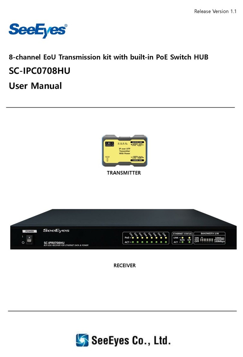
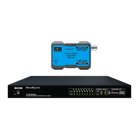
SeeEyes SC-IPC3001G User manual

Release Version 1.0
1-channel IP 1Giga Uplink Transmission System
SC-IPC3001G
User Guide
SC-IPR3001G
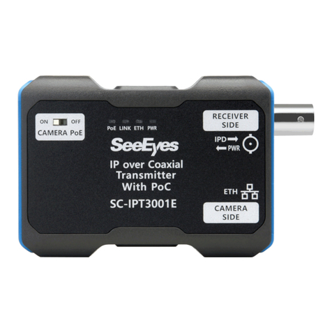
SC-IPT3001G

Release Version 1.0
1
Precautionary and Safety Guidelines
The content of this guideline is intended to protect the safety of the user and prevent damage to property.
Please read these operating instructions carefully and use the device as intended.
Warning (Failure to adhere to any of the following guidelines could result in
serious injury or death for someone.)
■Make sure to install the product after unplugging the power cord. Also, do not use many
power plugs at the same time.
- Doing so could result in abnormal heat, fire, and electric shock.
■Do not leave the device in a place where water will fall or splash. Also, don't put anything
with water on it, such as a flower vase.
- If liquid gets inside the device, it may cause malfunction or fire
■Do not bend the power cord with excessive force. Make sure that the power cord is not
crushed by heavy objects.
- It can cause fire.
■Do not open the cover arbitrarily as there is a high voltage part in this device. Never
disassemble, repair, or modify it.
- Improper work can lead to fire, electric shock and injuries.
■Do not install this product in a location with high humidity, dust, or soot.
- Electric shock and fire may result.
■Do not pull on the section of the power cord and do not pull out the power plug with wet
hands. If the power cord is loose, do not plug it in.
- There is a risk of fire and electric shock.
■Always keep the location clean and dust-free during or after the installation of the device.
When cleaning the device, wipe it with a dry cloth and do not use water, thinner, or organic
solvents.
- Doing so could result in malfunction or fire
■Store the device in a cool place out of direct sunlight. Keep it at a reasonable temperature
and avoid heating devices such as candles or heaters. Also, keep the equipment or tools away
from places where people go in and out.
- There is a risk of damage to the surface of the device and the risk of failure, electric shock or fire.
■Be aware of potential hazards in the workplace, such as wet floor, ungrounded power
extension cords, old power cords and lack of protective earth. If you have any problems, contact
your seller or specialist.
- Doing so could result in fire or electric shock.
■The input voltage required to operate this equipment must have a voltage fluctuation range
within 10% of the specified voltage, and the outlet must be grounded. Also, do not use
electrical appliances such as hair dryers, irons, and refrigerators with the outlet to which the
power plug is connected.
- Doing so could result in abnormal heat, fire, or electric shock.
■During thunderstorms or lightning strikes, pay attention to safety and pull out the power
plug.

Release Version 1.0
2
Caution (Failure to comply with any of the following guidelines may cause
injury or property damage.)
■The correct ambient temperature and humidity are recommended.
- Avoid extremely high temperatures (above 50 ° C) or low (below -10 ° C) and humid conditions.
■Install the device in a well-ventilated place and avoid direct sunlight or heating devices.
■Strong shocks or vibrations can lead to device failures. Be careful when using the device.
- Install the device in a location free from strong vibration.
■Be sure to connect the power cord to a grounded outlet.
- Electric shock (electric shock) and personal injury can result.
■When this unit is used near equipment that generates strong radio waves, such as a
television set, radios (TRANCEIVER, walkie-talkie, etc.), repeaters, etc., it may affect the video
signal and abnormality such as noise or cracks may appear in the picture. Do not use it as it
may cause the device to malfunction.
■The transmission distance may differ depending on the type of coaxial cable and UTP cable.
■During thunderstorms or lightning, ensure your safety and pull out the power plug.
■To prevent water droplets such as rainwater / dew / fog from entering the inside of the
device via the cable, lay the cable in a U-shape when connecting.
■If you notice unusual noises or smells, pull out the power plug immediately and contact the
dealer or the service centre.
- There is a risk of fire and electric shock.
■If you have any problems or questions other than those listed above, see the
troubleshooting guide at the end. If you need help from a professional technician, contact our
A/S centre.
■When extending or terminating a coaxial cable, be sure to connect it as follows.
- BNC-M (male) - BNC-JJ - BNC-M (male): Connection example BNC connector (used for HD-SDI)
■Insulate the part where the cable connects to the connector so that the metal part is not
exposed.
■The UTP cable (Unshielded Twisted Pair) is only intended for indoor use. Use shielded twisted
pair (STP) cable for outdoor use.
- Use standard CAT.5e or higher UTP cables.
■Since this product has a PoC function, the connected device may malfunction if it is
connected to other devices. Therefore, read the instruction manual carefully before use.
■Class A equipment (commercial broadcast and communication equipment)
- This device is an electromagnetic wave device (Class A). It is recommended that the seller or user take this
into account and the device is not intended for household use
■Be careful not to change the network cabling.

Release Version 1.0
3
1. Introduction
1-1. summary
The pair consists of SC-IPT3001G (Tx.) And SC-IPR3001G (Rx.) As IP-PoE kit (supply of the camera
via PoE by sending / receiving PoC)
Since the PoC (Power over Coaxial) function is installed, it is possible to supply the transmitter
and camera with power, so that no separate power line construction is required.
In addition, the short transmission distance (100 m or less) of conventional network systems can
be overcome by transmitting Ethernet data over long distances between the SC-IPT3001G (Tx.)
and SC-IPR3001G (Rx.) using a coaxial cable.
1-2. Product Features
•1 Gbit/s bandwidth support between transmitter / receiver
•Supports up to 780 Mbit/s (370 Mbit/s full duplex) (based on RG-59)
•The maximum transmission distance is 900 m based on RG-59 (see 5-1. Transmission Distance
Table)
•Power supply for IP PoE camera available (PoE type B support)
•Safe power transmission with automatic line diagnosis function
•PoE ON / OFF can be set on the transmitter (supports both PoE and non-PoE cameras)
•Supports the automatic recovery function in the event of an error
•Pairing to improve symptoms of network glitches during installation with multiple sets
•The receiver's pairing button for easy pairing
•Pairing is possible immediately with the pairing button, even in a 4: 1 configuration
2. Components
SC-IPT3001G
SC-IPR3001G
power cord
DC48V 1A
adapter
User
Guide

Release Version 1.0
4
3. Names and functions of each part
3-1. SC-IPT3001G
①Receiver Side: Receiver connection terminal and video output terminal.
②Status LED
Location
Name
LED status indication
function
Top
Link
Off
No Link
Red
Poor Link
Green Blink
Link OK / Act OK
Bottom
PWR
Off
No power input
Green On
Successful power connection
Red Blink
Camera side power supply error (short circuit,
disconnection, overcurrent)
Red On
PoE power switch off status
Orange Blink
Pairing status
③Camera Side: IP camera connector
Green LED
Ethernet Activity LED (Green Blink)
Orange LED
Ethernet Link LED (Giga Link : Orange On)
※When connecting with 100Mbps products, the Orange LED may be blinking.
④CAM PoE: PoE power supply setting switch.
※When connecting a PoE IP camera, set the CAMERA PoE switch to ON.
※When the product is shipped, the PoE switch is set to PoE ON.
※If you connect an IP camera that does not support PoE, set the CAMERA PoE switch to OFF.
⑤Extra Power Port: DC 48V to DC 56V input terminal.
※It is a terminal for connecting an additional power source when power is insufficient. Please
connect an external adapter when the camera supply power is insufficient depending on the
transmission distance.
④
⑤
①
②
②
③

Release Version 1.0
5
3-2. SC-IPR3001G
①Transmitter Side: Transmitter connection terminal and video input terminal.
②Pair: The pairing button (enables the transmitter and receiver to be connected and operated).
Button press time
LED status (PWR LED)
function
2-5 seconds
Flashes once every 0.5
seconds
Pairing
※When the LED of LINK is lit, the transmitter and receiver connection is successful.
※Even if the pairing fails on the first attempt, it will try itself until it is successful.
※Please disconnect the transmitter adapter during pairing.
③LED Status Indicator
Location
Name
LED Status indicator
Function
Top
Link
Off
No Link
Red
Poor Link
Green Blink
Link OK / Act OK
Bottom
PWR
Off
No power input
Green On
Successful power connection
Red Blink
Camera side power supply error (short circuit,
disconnection, overcurrent)
Orange Blink
Pairing status
④NVR Side : NVR or PoE hub connection port.
Green LED
Ethernet Activity LED (Green Blink)
Orange LED
Ethernet Link LED (Giga Link : Orange On)
※When connecting with 100Mbps products, the Orange LED may be blinking.
⑤POWER IN: DC 48V to DC 56V input terminal.
※The power supply and distance to the camera may vary depending on the adapter that is
connected.
①
②
③
④
⑤

Release Version 1.0
6
4. Product configuration example
4-1. 24 cameras via PoE Switch Hub
5. Transmission distance per cable
5-1. 1 to 1 configuration
Product
SC-IPC3001G
Specificati
ons
Max. transmission distance
Max. 900m (RG-59)
Power
Power consumption
Max. 4W
maximum output
Max. 30W
Actual
measure
ment
input power
DC 48V/1.04A
DC 56V/1.2A
cable type
transmission
distance
Bandwidth
(TCP/IP)
Half Duplex
PoE
output
Bandwidth
(TCP/IP)
Full Duplex
PoE
output
RG-58
200 m
743 Mbps
21W
375 Mbps
30W
400 m
538 Mbps
11.8W
270 Mbps
23W
600 m
270 Mbps
7.6W
137 Mbps
15.9W
800 m
154 Mbps
5.4W
78 Mbps
12W
RG-59
200 m
778 Mbps
19W
350 Mbps
30W
400 m
608 Mbps
6W
305 Mbps
13W
600 m
377 Mbps
4W
200 Mbps
9W
800 m
280 Mbps
3W
140 Mbps
7W
900 m
230 Mbps
2W
110 Mbps
5.8W
※The camera is supplied with power using the PoE type B midspan method.
※The distance and quality of the video transmission can vary depending on the cable type, the
operating status of the plug and the type of connection adapter.

Release Version 1.0
7
※The transmission distance may vary slightly depending on the quality of the coaxial cable used
and the quality of the connector connection.
※Depending on the power specifications of the camera to be used, there may be a difference of
approx. 20-30% to the available power values in the table.
※The cable transmission distance may vary depending on the camera and NVR specifications.
※When using the PoE function of the transmitter, the transmission distance of the coaxial cable
may vary depending on the camera type.
In particular, use a dedicated adapter for power-consuming IPTZ cameras and cameras with high
IRLEDs.
5-2. Product Installation Precautions
※Use a dedicated adapter for each product separately. Powering multiple products with one
adapter is not recommended.
※It is not recommended when the products are in contact or connected to each other.
※When installing the product, press the function button for 2 to 5 seconds to pair.
※Remove the transmitter power supply during pairing
(Pairing function does not work if the transmitter power supply is connected)
※Switch off PoE on the transmitter when using the camera power supply unit.
※In the event of an abnormal picture or loss of connection during use, perform pairing again.
※If the receiver is supplied with power via PoE, we do not recommend connecting the adapter to
the DC socket.
※When installing the product using PoE power supply, it is recommended to check the video and
ground the camera.
※When using a surge protector, the cable distance between the camera and transmitter should be
less than 50 m.
※For 4-camera configuration, it is recommended that the distance from the receiver to each
transmitter is a maximum of 600 m (based on RG-6).

Release Version 1.0
8
※CABLE PIN Array (1000, Mode B)
Number
Color
10/100/1000
Mode B
T568A
T568B
1
White + Green
White and
orange.
TxRx A+
2
Green
Orange
TxRx A-
3
White + Orange
White + Green
TxRx B+
4
Blue
Blue
TxRx C+
DC+
5
White + Blue
White + Blue
TxRx C-
DC+
6
Orange
Green
TxRx B-
7
White + Brown
White + Brown
TxRx D+
DC-
8
Brown
Brown
TxRx D-
DC-

Release Version 1.0
9
6. Troubleshooting
Symptom
Identification method
No power.
•Check the power supply input.
•Make sure that the dedicated adapter is used.
•Check if the PWR LED of the product works normally.
•Check the coaxial cable connection.
No video.
•Check if the LINK LED of the product works normally.
•Check if the LED of the RJ-45 terminal works normally.
•Check whether the transmission distance is greater than the
recommended transmission distance.
•Verify that the network cable pins are arranged correctly.
•When using the PoE function, make sure that the PoE switch on
the transmitter is set to ON.
PoE doesn't funtion
•Verify that the network cable pins are arranged correctly.
•Check if the NETWORK CABLE transmission distance is within
100m. (Based on CAT.5e)
•When using the PoE function, make sure that the PoE switch on
the transmitter is set to ON.
•Make sure your IP camera is PoE capable.
Network connection
is unstable
•Verify that the network cable pins are arranged correctly.
•Check the area for radio devices or devices that generate strong
radio waves.
•Check whether the network configuration is designed correctly.
(Receiver and transmitter 1: 1 configuration is recommended)
•Perform pairing again if a new network configuration or a network
configuration is changed.

Release Version 1.0
10
7. Specification
MODEL
SC-IPT3001G
Power output
Midspan PoE supported (Type B Only, PoE SW On/Off)
Transmission bandwidth
1Gbps (PHY RATE)
Connection port
RECEIVER SIDE
BNC-F, 75Ω
CAMERA SIDE
RJ-45 (TIA/EIA568B Type)
EXTRA POWER
PORT
DC-Jack
RJ-45 Connector
1Pin: TX +, 2Pin: TX-, 3Pin: RX+, 4Pin: PWR+
5Pin: PWR+, 6Pin: RX-, 7Pin: PWR-, 8Pin: PWR-
LED Status
Indicator
PWR
Green On: Successful connection
Orange Blink : Pairing status
Red Blink : Camera side power supply error (short circuit,
disconnection, overcurrent)
Red On: PoE Switch off
Link
Off: No Link
Red On: Poor Link
Green Blink: Link OK / Act OK
PoE Switch
On: PoE power supply to camera
Off: PoE function is off
Operating Temperature /
Operating Humidity
-10℃ ~ 50℃ / 0 ~ 80%
Material / Weight
Aluminum / 160g
Dimensions
148(W) x 25(H) x 60(D)mm

Release Version 1.0
11
MODEL
SC-IPR3001G
power input
DC 48V/56V Adapter or PoE(IEEE802/3at)
Power Consumption
6W
Maximum
transmission
distance
RG-59
(Based on
10Ω/200m)
Separate camera power supply: 900m
30W camera power supply: 200m (56V)
Transmission bandwidth
1Gbps (PHY RATE)
Connection port
TRASMITTER SIDE
BNC-F, 75Ω
NVR SIDE
RJ-45 (TIA/EIA568B Type)
POWER PORT
DC-Jack
RJ-45 Connector
1Pin: TX +, 2Pin: TX-, 3Pin: RX+, 4Pin: PWR+
5Pin: PWR+, 6Pin: RX-, 7Pin: PWR-, 8Pin: PWR-
LED status
indication
PWR
Green On: Successful connection
Orange Blink : Pairing
Red Blink : Transmitter side power supply error (short circuit,
disconnection, overcurrent)
Link
Off: No Link
Red On: Poor Link
Green Blink: Link OK / Act OK
Operating Temperature /
Operating Humidity
-10℃~ 50℃/ 0 ~ 80%
Material / Weight
Aluminum / 162g
Dimensions
148(W) x 25(H) x 60(D)mm

Release Version 1.0
12
8. Warranty Certificate
This product has passed thorough quality control and test, and if this gets broken during
normal use, we provide the two-year warranty service.
Model No.
Serial No.
Distributor
Date you purchased
Place you purchased
Warranty Period
Two (2) year from the date of purchase
Purchaser
Name
Address
•Please check this warranty indication first.
•Please contact your distributor after checking out any defect in the products.
•The standard for repairing, replacement or reimbursement follows Customer.
•Warranty content any defect under normal use within the warranty service period we give
you free repair service according to the warranty certificate.
•We charge you with the fee of parts and service despite of free warranty service period.
Any breakage made without care such as:
- Breakdown due to natural disasters (lightning, fire, flood, tsunami, etc.)
- When disassembled or repaired by the user
- When connecting power other than rated power.
- When you want to reassemble for full system or replace parts within warranty
service period.
- When unauthorized person modified or made damage on the product trying to
repair it.
- Failure due to careless handling of the user
- When replacing consumables
- Lightning strike.
•Please note that we don’t support the breakage after warranty service period expired. If
the customer wants to get it repaired, we charge them with the fee.
•The specification is subject to change without prior notice for quality improvement.
This manual suits for next models
2
Table of contents
Other SeeEyes Microphone System manuals


