SeeEyes SC-IPT1204P User manual

Release Version 1.1
4-ch IP Transmitter with built-in PoE HUB
SC-IPT1204P
User Guide
SC-IPT1204P

Release Version 1.1
1
Precaution and Safety Guidelines
The content of this guideline is intended to protect user safety and prevent property damage.
Please read this user guide carefully and use the device properly
Warning (Failure to adhere to any of the following guidelines could result in serious
injury or death for someone.)
■Be sure to install the product after unplugging the power cord. Also, do not use many power
plugs at the same time.
- It may cause abnormal heat, fire and electric shock.
■Do not leave the device in a place where water will fall or splash. Also, do not place anything
with water on it, such as a vase of flowers.
- It may cause malfunction or fire if liquid goes into the device.
■Do not open the lid arbitrarily as this device has high voltage part inside. Never disassemble,
repair or modify it.
- By abnormal working, it may cause fire, electric shock and personal injury.
■Do not install this product in places with high humidity, dust, or soot.
- It may cause electric shock and fire.
■Always keep the location of the appliance clean during or after installation to prevent dust.
Especially when cleaning the device, wipe it with dry towel and do not use water, thinner or
organic solvent.
- It may damage the case of this device, and cause malfunction or electric shock.
■Keep the device in a cool place where doesn’t let direct sunlight. Keep it at a proper
temperature and avoid heating appliances like candle or heater. Also, keep the equipment or
tools away from places where people come and go.
- It may cause fire.
■Pay attention to possible hazards in the workplace, such as wet floor, ungrounded power
extension cables, old power cords and a lack of safety earth. Consult your place of purchase or
professional if problems arise.
- It may cause fire and electric shock.
■Concerning the input voltage for operating this device, a voltage range must be within 10%
of rated voltage. Also, do not use a heat source such as a hair dryer, iron and refrigerator to the
same power unit.
- It may cause abnormal heat, fire and electric shock.
■Disconnect the power plug with care during thunder and lightning.
■Do not bend the power cord by excessive force. Make sure the power cord is not crushed by
heavy things.
- It may cause fire.
■When connecting cables, install as “U” shape in order to prevent rainwater/dew/fog from
getting into the product.

Release Version 1.1
2
Caution (If you do not keep any of the below guidelines, you may get injured or suffer
property loss.)
■Avoid installing near strong magnetic fields or radio waves and wireless devices such as radio
or TV.
- Install in a place that is free from magnetic, radio, or excessive vibration.
■Proper ambient temperature and humidity are recommended.
- Avoid extremely high temperatures(over 50°C) or low(below -10°C), and humid conditions.
■Do not place heavy items on the product or let foreign substances enter inside the device.
- It may cause failure.
■Install in well ventilated place, and avoid direct sunlight or heat appliance.
■Strong shock or vibration may cause device failure. Be careful when using the device.
- Install in a place without severe vibration.
■If you notice any unusual noise or smell, unplug the power supply immediately and contact
the place of purchase or service center.
- There may be a risk of fire and electric shock.
■Ventilate the system operating room and secure the main body cover.
- It may be the cause of failure by environmental factors.
■Refer the device to the service center and get regular checkup to maintain the performance
of the system.
- We are not responsible for any damages caused by user’s carelessness.
■Be sure to plug the power cord with grounded outlet.
- There is a risk of electrical shock and personal injury.
■Place the power plug in a location that is easy to operate.
- If a failure of the product occurred, the power plug must be unplugged to power down
completely. The power button on the main body does not completely disconnect power.
■Do not use this device in close proximity to a device that produces strong waves such as
radio set(TRANCEIVER, Walkie-talkie, etc.) or repeater. It may affect video signal, or cause
disorders such as noise or crack on the screen.
■The transmission medium(CABLE) must be a UTP(CAT.5e) or coaxial cable.
■Be careful not to change the cable array during installation. (Refer to ‘4. CABLE PIN
Configuration’ on page 5.)
■Make sure to check the power output of each port when connecting two or more cameras or
this products, since the maximum output power of the CAMERA PORT of the product is 30W.
- The power output is limited depending on the power consumption of the camera.
■UTP(Unshielded Twisted Pair) Cable is for indoor use only. Use a STP(Shield Twisted Pair)
Cable which is covered for outdoor use.
■The transmission distance may vary depending on the UTP cable type.
■Refer to the user’s manual for problems or questions besides the above. Contact our service
center if you need assistance from a professional technician.
Release Version 1.1
3
1. Introduction
1-1. Overview
SC-IPT1204P is a hybrid network data transmitter with built-in 4CH PoE HUB and EoC(Ethernet Over
Coax.) function.
This transmission device transmits Ethernet data from four IP cameras over only one coaxial cable
and receives operating power from receiver such as SC-IPR07P or SC-IPR0708H, therefore, it shortens
construction period and reduce installation cost.
Also, this item improves short-distance of typical network systems by extending transmission distance
up to 500m and supplies power to 4CH PoE Cameras with DC Jack for external power supply.
1-2. Features
•4CH PoE HUB function
•EoC (Ethernet Over Coax) function
•Supports PoE (Camera Side : Endspan x 4CH, NVR Side : End/Midspan x 1CH)
•Supports EoC (when connecting with SC-IPR07P)
•4 IP cameras transmission over 1 Coax. cable
(Max. 8 cameras transmission over one coaxial cable by adding 1pc of transmitter via extra
NVR(RJ-45) port provided)
•Provides extension switch for setting bandwidth of CAMERA side
Switch On : 10Mbps / Max. 250m (CAT.5e)
Switch OFF : 100Mbps / Max. 100m (CAT.5e)
•Power Input : DC 48~56V Adapter (DC Adapter power priority)
Supports PoC (when connecting with SC-IPR07P)
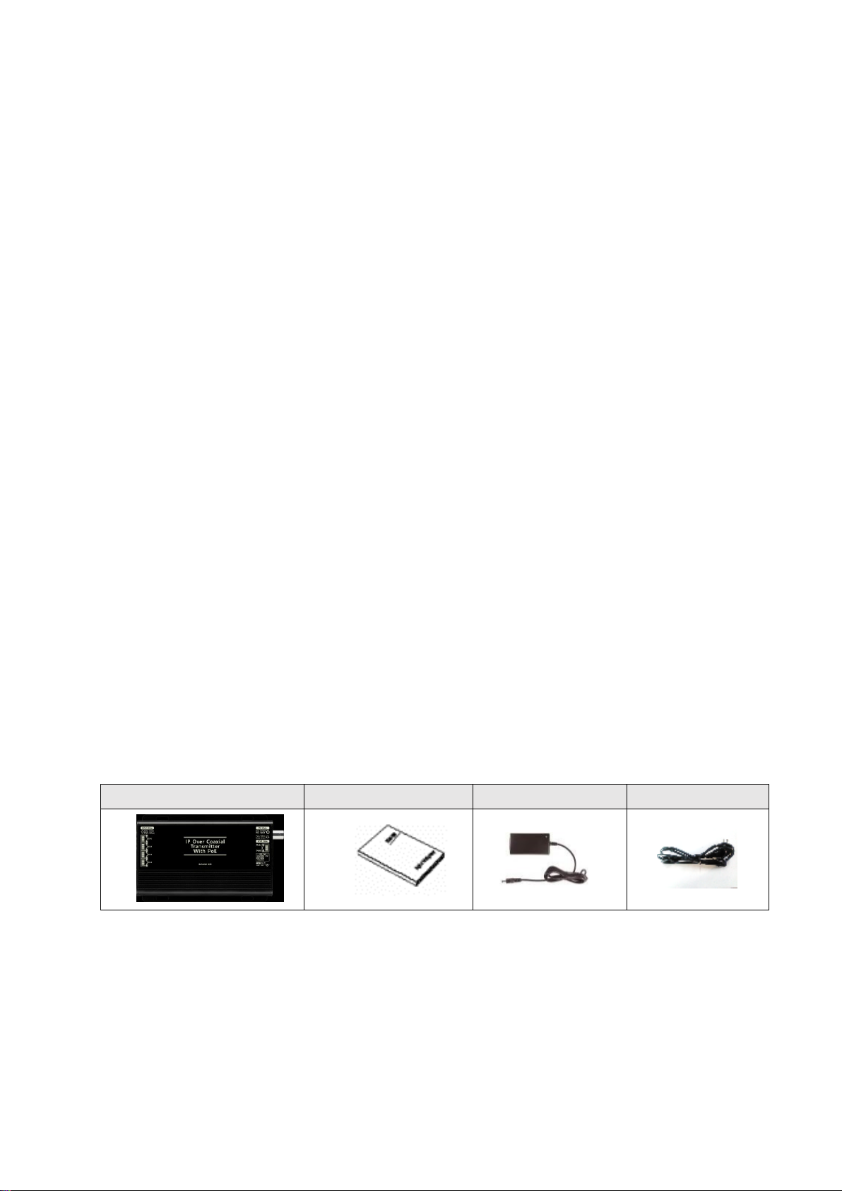
2. Components
SC-IPT1204P
User’s Manual
DC 56V Adapter
Power Cord
※The accessories included in the product are subject to change.
Release Version 1.1
4
⑥
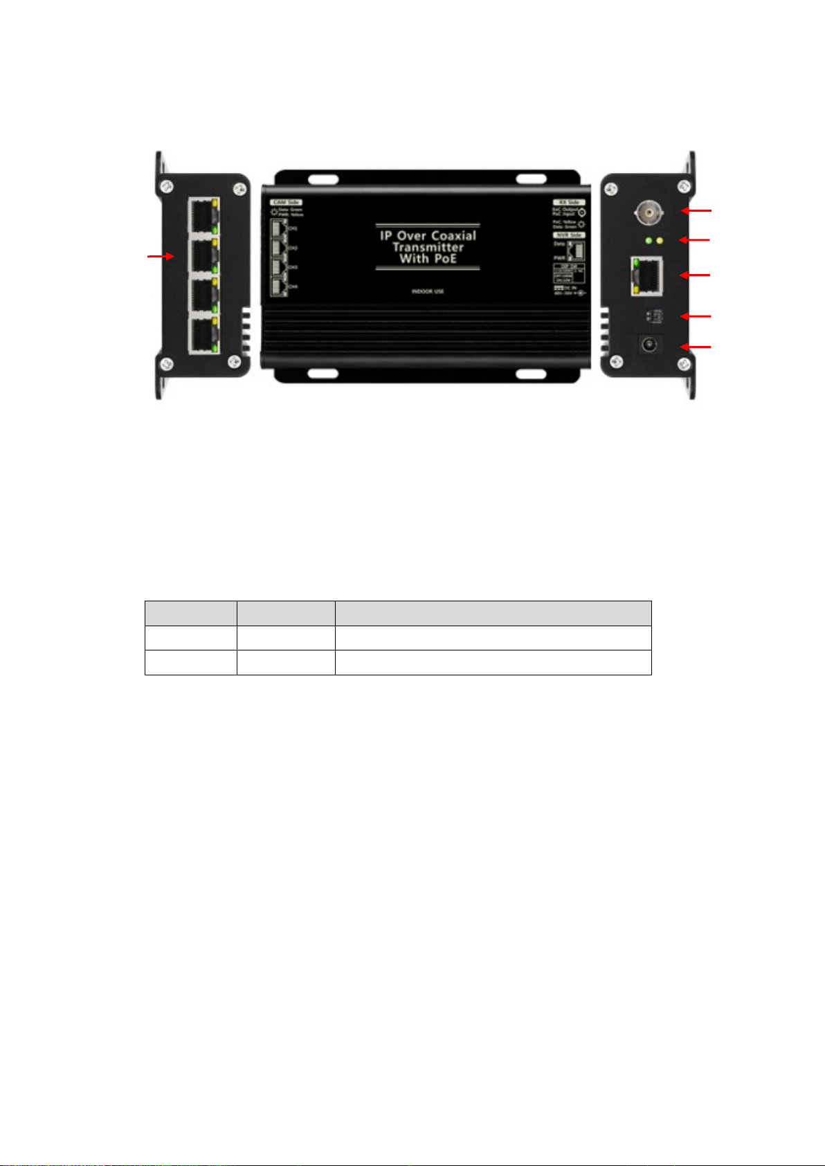
3. Product Parts and Functions
①CAMERA SIDE : IP camera connection port. PoE Type A supported. (IEEE802.3 af/at)
- Port to supply power to camera with PoE or receive camera Data.
②RX SIDE : SC-IPR07P connection port. PoC(Power over Coax.) supported (when connecting SC-
IPR07P)
③EoC Status LED : IPR07P PoC Link LED, EoC Data LED
④NVR SIDE : NVR connection port.
⑤Bandwidth Select Switch : 100Mbps, 10Mbps setting supported
SWITCH
Bandwidth
Transmission Distance
ON
10Mbps
Max. 250m over CAT.5e
OFF
100Mbps
Max. 100m over CAT.5e (Default)
※Please be noted that if the bandwidth exceeds 10Mbps after setting the switch to 10Mbps,
a problem may occur with the video.
※The factory default of the Bandwidth Switch is 100Mbps.
※When the distance between camera and CAMERA SIDE port is over 100m, the bandwidth setting
is automatically set to 10Mbps. If the automatic setting is not done depending on the
specification of the devices, turn the bandwidth switch on manually.
⑥DC 48V~56V INPUT: Port to input DC adapter (48V or 56V) power.
※Please use exclusive DC56V adapter for stable power supply for each PoE port.
④
⑤
①
③
②
Release Version 1.1
5
<POWER, LINK/ACT Status Display LED>
※Caution
•Supply external power to use this transmitter as a PoE Switch Hub.
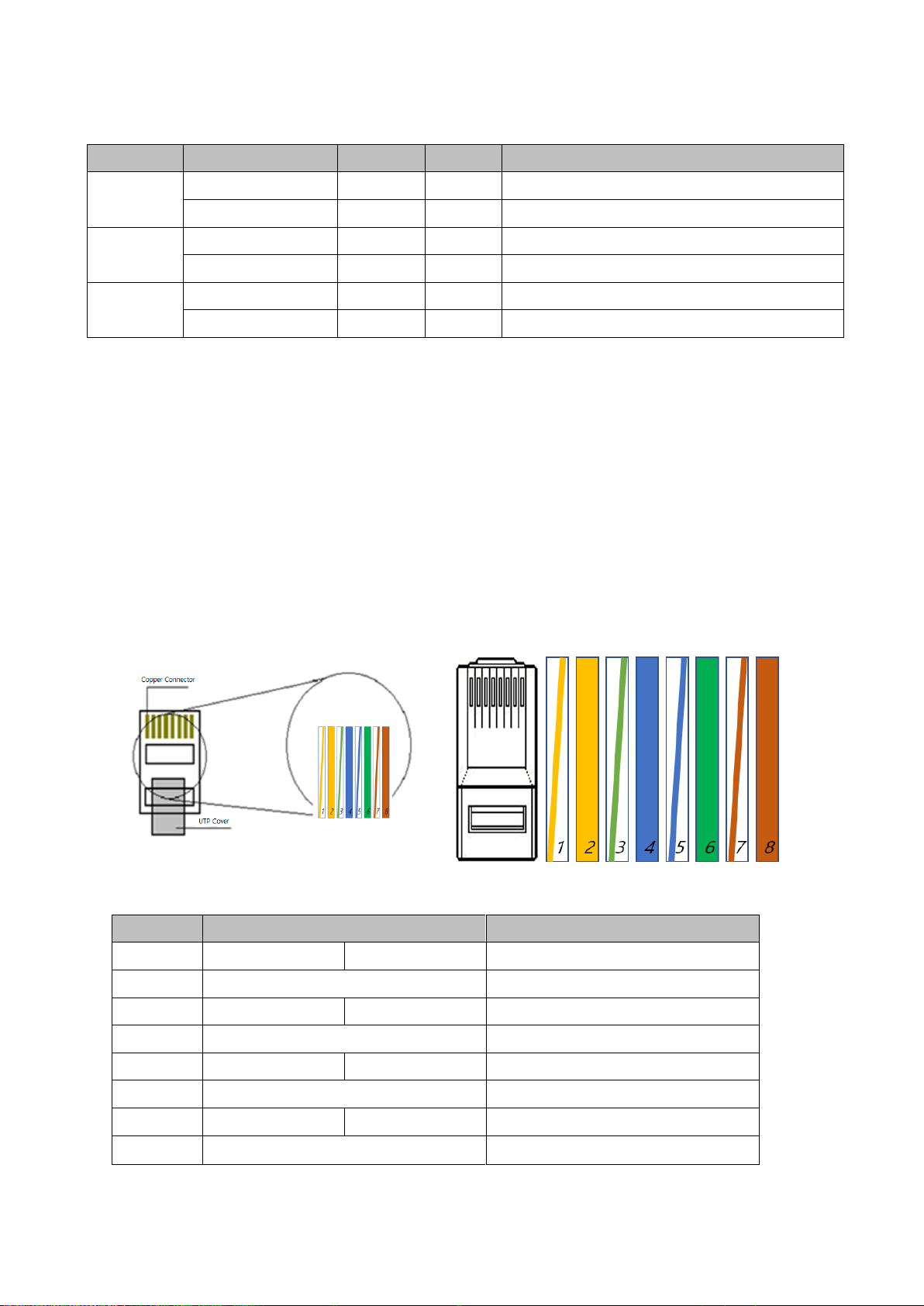
4. CABLE PIN Configuration (TIA / EIA 568B Type)
No.
Color
Function
1
White
Orange
TX+
2
Orange
TX-
3
White
Green
RX+
4
Blue
PWR+
5
White
Blue
PWR+
6
Green
RX-
7
White
Brown
PWR-
8
Brown
PWR-
LED Type
Indicator
Color
State
Description
EoC Status
LED
Operation Power
Yellow
On
Operation power OK
EoC Data
Green
Flashing
EoC Data Transmitting & Receiving OK
Cam Side
1X4 RJ45
PoE Output
Yellow
On
PoE Output OK
Ethernet Data
Green
Flashing
Ethernet Data Transmitting & Receiving OK
NVR Side
RJ45
Operation Power
Yellow
On
Operation Power OK
Ethernet Data
Green
Flashing
Ethernet Data Transmitting & Receiving OK

Release Version 1.1
6
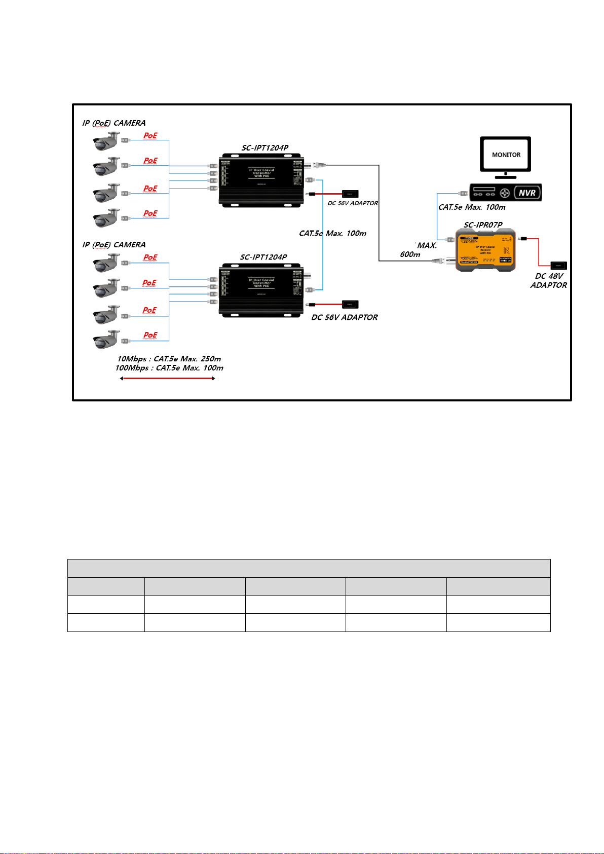
5. Connection Diagrams
5-1. In case of using as a 4CH PoE HUB
5-2. In case of using with EoC(Ethernet over Coax.) device (SC-IPR07P)
RG-6
Release Version 1.1
7
5-3. In case of using 8CH transmission configuration
※You may need to change the adapter depending on the camera power consumption.
※Please configure general communication network (Internet/In-company, house) separated to
CCTV network.
※Please be noted that if the bandwidth exceeds 10Mbps after setting the switch to 10Mbps, a
problem may occur with the video.
5-5. Recommended PoE Camera Power Consumption
PoE Camera Power Consumption (Max. Power Output)
Adapter
PoE Camera #1
PoE Camera #2
PoE Camera #3
PoE Camera #4
DC 56V
14W
14W
14W
14W
DC 48V
10W
10W
10W
10W
※Values in above table may vary depending on the type of camera and cable.
※Valued in above table may be changed when using PoE switch HUB.
※When connecting a camera with large power consumption or inrush current, please use a 56V
adapter or apply PoE+ to the product.
※When using PoE function of the transmitter, transmission distance may vary depending on
the camera type.
Especially for cameras with high power consumption such as IP PTZ camera or IP cameras
with many IR LEDs, please use additional adapter for camera power.
<PoE Camera Power Consumption Table Based on DC Adapter 48V,1.0A, 56V 1.11A>
RG-6

Release Version 1.1
8
6. Trouble Shooting Method
Condition
Check Method
Power is not
supplied.
•Check the power cable connection state.
•Check if the exclusive adapter is used.
•Check the PoE switch hub connection state.
•Check the CABLE PIN configuration state.
Video is not
displayed.
•Check the CABLE PIN configuration state.
•Check the cable transmission distance.
•Check the ground state.
•Check if the camera model is able to input PoE.
•Check if the camera is compatible with NVR.
Video status is
uneven.
•Check the CABLE PIN configuration state.
•Check the cable transmission distance.
•Check the ground state of the product.
•Check the setting of camera.
(Transmission video quality, frame rate, resolution, etc.)
•Check if the bandwidth is over 10Mbps after setting Bandwidth
Switch as 10M.
Network connection
state is abnormal.
•Check the NETWORK CABLE configuration.
•Check if there is any equipment that generates radio or strong
waves in the surrounding environment.
•Check if the Network configuration is installed properly.

Release Version 1.1
9
7. Specifications
Model No.
SC-IPT1204P
Power
Input
DC Power
DC 48V or DC 56V Adapter
PoE Power
PoE IEEE 802.3af / 802.3at, Endspan / Midspan (Mode A / Mode B)
PoE Output
CAMERA PORT
Max 30W, Standard PoE, IEEE802.3 af/at Mode A
Power Consumption
Max 1W (No-load Condition)
CAM SIDE
Transmission Distance (Max.)
In 100Mbps : 100m (CAT.5e)
In 10Mbps : 250m (CAT.5e)
RX SIDE
Transmission Distance (Max.)
500m (RG-6)
Connection
Port
NVR PORT
RJ-45 1Port (TIA/EIA568B Type)
CAMERA PORT
1x4 RJ-45 1Port (TIA/EIA568B Type)
EoC PORT
BNC-F 1Port , 75ohm
POWER
DC JACK 2.0pi
RJ-45 Connector
Pin Assignment(Polarity)
1Pin: TX(+), PWR(+) 2Pin: TX(-), PWR(+)
3Pin: RX(+), PWR(-) 6Pin: RX(-), PWR(-)
Bandwidth Switch
Change CAM Side Transmission Speed (100Mbps , 10Mbps)
Transmission Bandwidth
10/100Mbps (Full duplex)
Temperature / Humidity
-10°C ~ +50°C / 0 ~ 80%
Case Material / Weight
Aluminum / 290g
Dimensions (mm)
159(W) x 92.5(H) x 34.7(D)mm
※Using the LAN cable extension gender (coupler) causes signal attenuation. The use of multiple
gender connections is not recommended.
※Cable transmission distance may vary depending on the specifications of camera and NVR.
※When using the camera PoE function, the transmission distance may vary depending on the type
of camera.

Release Version 1.1
10
8. Warranty Certificate
This product has passed thorough quality control and test, and if this gets broken during
normal use, we provide the two-year warranty service.
Model No.
Serial No.
Distributor
Date you purchased
Place you purchased
Warranty Period
Two (2) year from the date of purchase
Purchaser
Name
Address
•Please check this warranty indication first.
•Please contact your distributor after checking out any defect in the products.
•The standard for repairing, replacement or reimbursement follows Customer.
•Warranty content any defect under normal use within the warranty service period we
give you free repair service according to the warranty certificate.
•We charge you with the fee of parts and service despite of free warranty service period.
Any breakage made without care such as:
- Breakdown due to natural disasters (lightning, fire, flood, tsunami, etc.)
- When disassembled or repaired by the user
- When connecting power other than rated power.
- When you want to reassemble for full system or replace parts within warranty
service period.
- When unauthorized person modified or made damage on the product trying
to repair it.
- Failure due to careless handling of the user
- When replacing consumables
- Thunder stroke.
•Please note that we don’t support the breakage after warranty service period expired. If
the customer wants to get it repaired, we charge them with the fee.
•The specification is subject to change without prior notice for quality improvement.

Table of contents
Other SeeEyes Transmitter manuals


