GHM Delta OHM HVAC40 Series User manual

Operating manual
Humidity
and temperature
tran
smitters / Hygrostats
H
VAC40… series
www.deltaohm.com
English
Keep for future reference.
Companies / Brands of GHM

HVAC40… - 2-V1.1
TABLE OF CONTENTS
1INTRODUCTION.................................................................................................... 3
2TECHNICAL CHARACTERISTICS ............................................................................ 4
3INSTALLATION ..................................................................................................... 7
3.1 ELECTRICAL CONNECTIONS..................................................................................... 9
3.2 CONFIGURATION DIP SWITCHES IN THE MODELS WITH ANALOG OUTPUT................................ 10
3.3 CONFIGURATION DIP SWITCHES IN THE MODELS WITH RS485 DIGITAL OUTPUT...................... 11
3.4 CONFIGURATION DIP SWITCHES IN THE MODELS WITH RELAY OUTPUT.................................. 11
3.5 CONFIGURATION VIA THE SERIAL PORT...................................................................... 12
3.6 CONFIGURATION VIA THE INTERNAL BUTTONS (ONLY HVAC40R17…) ................................ 16
4ALARM OPERATING MODES (HVAC40R17…)....................................................... 18
5MODBUS-RTU (HVAC40S17…) ............................................................................ 20
6INSTRUMENT STORAGE ...................................................................................... 21
7SAFETY INSTRUCTIONS...................................................................................... 21
8ORDERING CODES .............................................................................................. 22

HVAC40… - 3-V1.1
1INTRODUCTION
HVAC40… series transmitters and hygrostats measure temperature, relative humidity
and dew point using an interchangeable relative humidity and temperature digital
sensor.
A stainless steel 10 µm filter protects the sensor against dust and particles (other fil-
ters are available for different applications).
The probe is available in three different versions:
•fixed vertical probe for wall mounting (HVAC40...TV);
•fixed probe with 2 m cable (HVAC40...TC.2);
•fixed duct horizontal probe (HVAC40...TO).
Available outputs, depending on the model:
•RS485 Modbus–RTU digital output (HVAC40S17…);
•0...10 V voltage analog output (HVAC40V17…);
•0...20 mA / 4...20 mA active current analog output (HVAC4017…);
•2-wire (current loop) 4...20 mA analog output (HVAC40A17…);
•ON/OFF relay switch (HVAC40R17…).
Versions with 4-digit LCD display (option L) are available, which allow the measured
parameters to be displayed.
In the versions with LCD, two LED indicators indicate the presence of the power sup-
ply and of an eventual alarm condition: exceeding of the set measurements thresh-
olds, in the versions with relay switch output; measurement detected outside the
measuring range, in the versions with analog or digital output.
The instruments are factory calibrated and ready for use.
The configuration can be made by connecting the serial port of the instrument to the
PC or by means of the quick configuration dip switches on the circuit board. The ver-
sions with relay switch output are equipped with two internal buttons for the configura-
tion via display.

HVAC40… - 4-V1.1
2TECHNICAL CHARACTERISTICS
Sensor Interchangeable digital relative humidity and temperature sensor
Measuring range 0…100 %RH / recommended 5…80 %RH
-20…+80 °C / -20…+80 °C Td
Resolution 0.1 %RH / 0.1 °C / 0.1 °C Td
Accuracy Typ. ± 2.5 %RH (5…80 %RH) @ t = 15…35 °C
Typ. ± 0.3 °C @ t = -20…70 °C / ± 0.5 °C @ t = remaining range
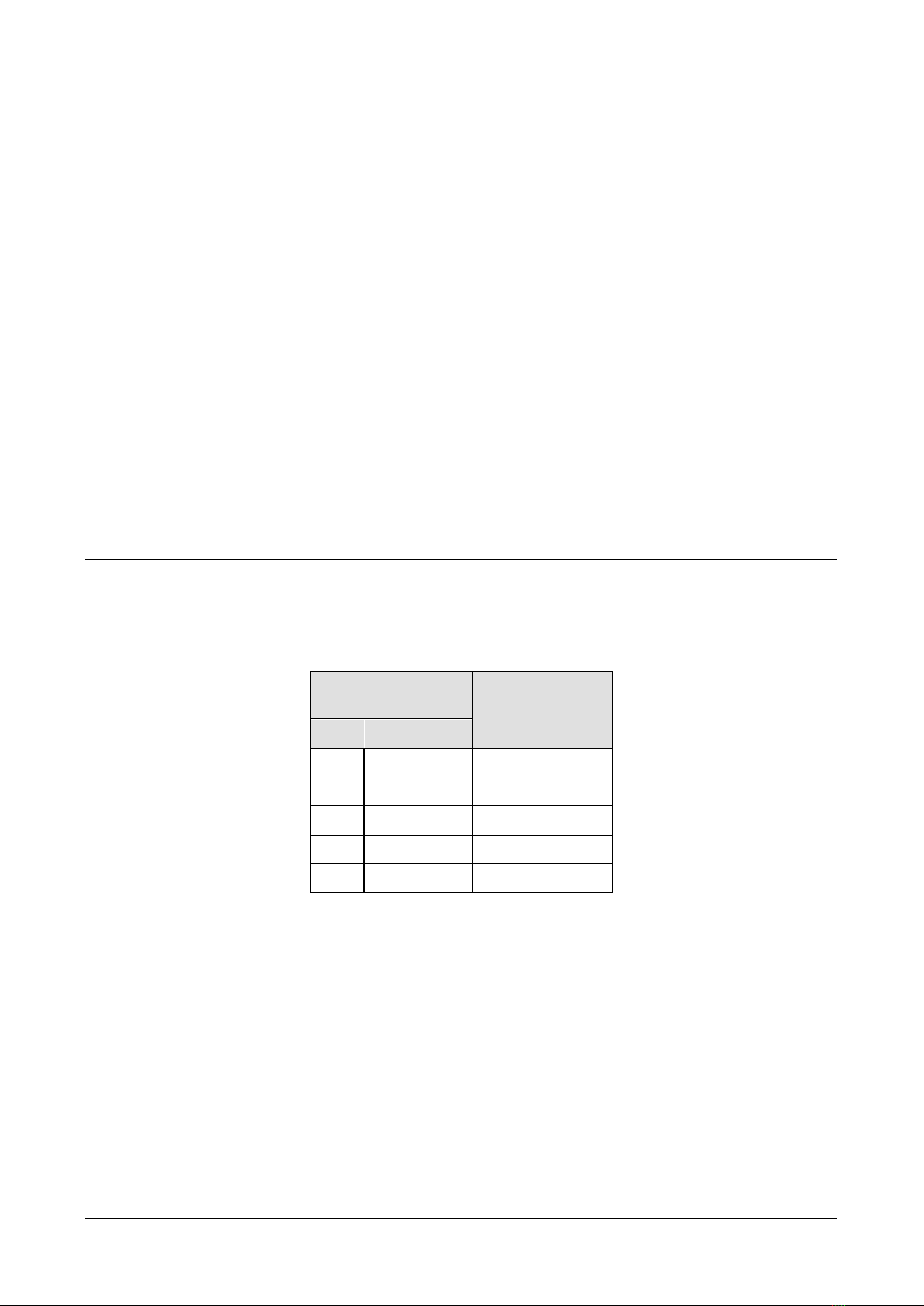
For the Dew Point see the table below
Long term drift Typ. < 0.25 %RH/year
Max. 0.03 °C/year
Response time 10 s (63% of final value with 1 m/s air flow)
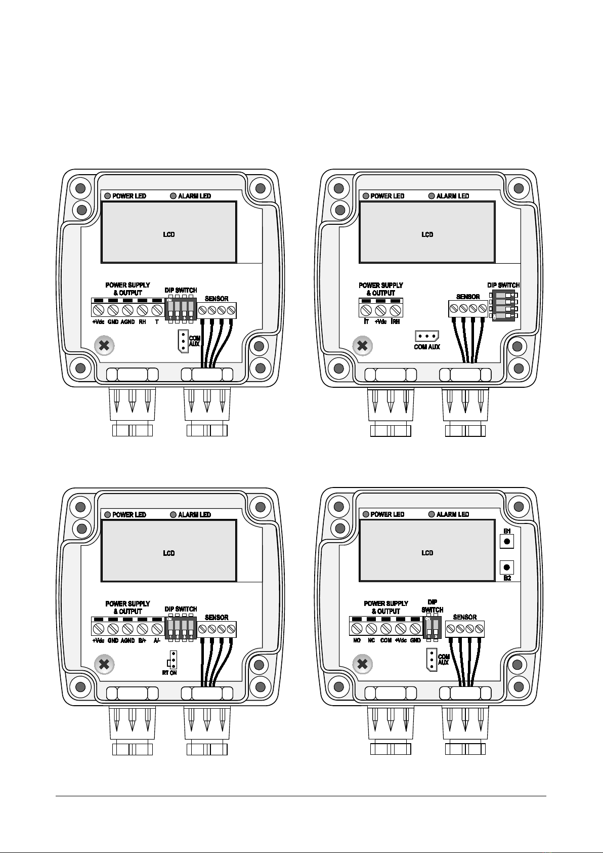
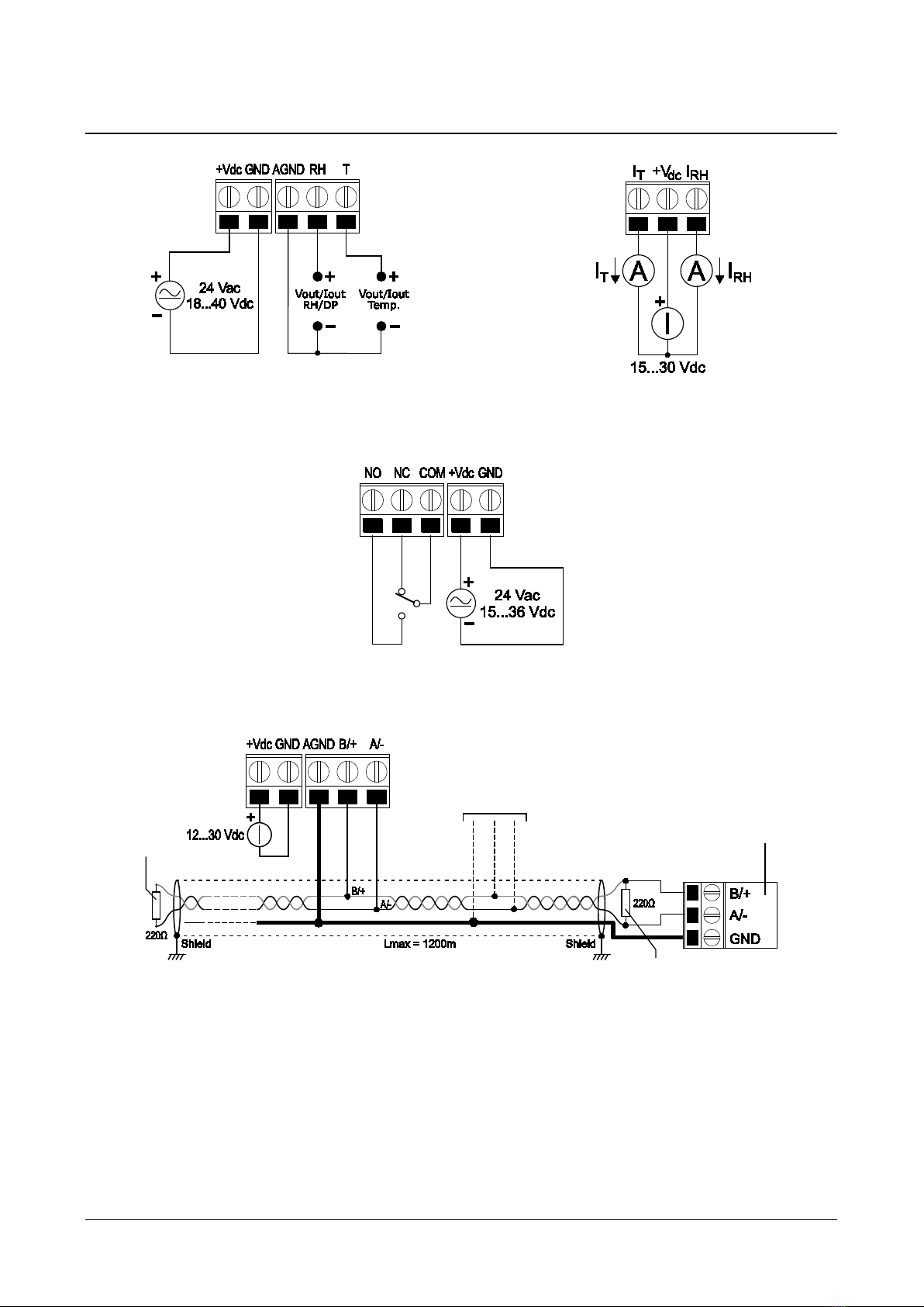
Output •HVAC4017…: Active analog 0…20 or 4…20 mA (RLmax = 500 Ω)
•HVAC40V17…: Analog 0…10 Vdc (RLmin = 10 kΩ)
•HVAC40A17…: 2-wire (current loop) 4…20 mA (RLmax = (Vdc-12)/0,022)
•HVAC40S17…: Digital RS485 Modbus-RTU
•HVAC40R
17…: ON/OFF relay switch with SPDT contact 3 A/250 Vac, 3 A/30
Vdc resistive load
The analog output goes to 22 mA or 11 V in case of measurement outside
the measuring range.
Alarm Front red LED: exceeding of the set measurements thresholds in
HVAC40R17… models,
measurement detected outside the measuring range
in the other models.
Internal buzzer in HVAC40R17… models.
Power supply •HVAC4017… and HVAC40V17…: 24 Vac ±10% or 18…40 Vdc
•HVAC40A17…: 15…30 Vdc
•HVAC40S17…: 12…30 Vdc
•HVAC40R17…: 24 Vac ±10% or 15…36 Vdc
Power consumption •HVAC4017…: 20 mA @ 24 Vdc and Iout=12 mA
•HVAC40V17…: 4 mA @ 24 Vdc
•HVAC40S17…: 2 mA @ 24 Vdc
•HVAC40R17…: < 1 W @ 24 Vdc
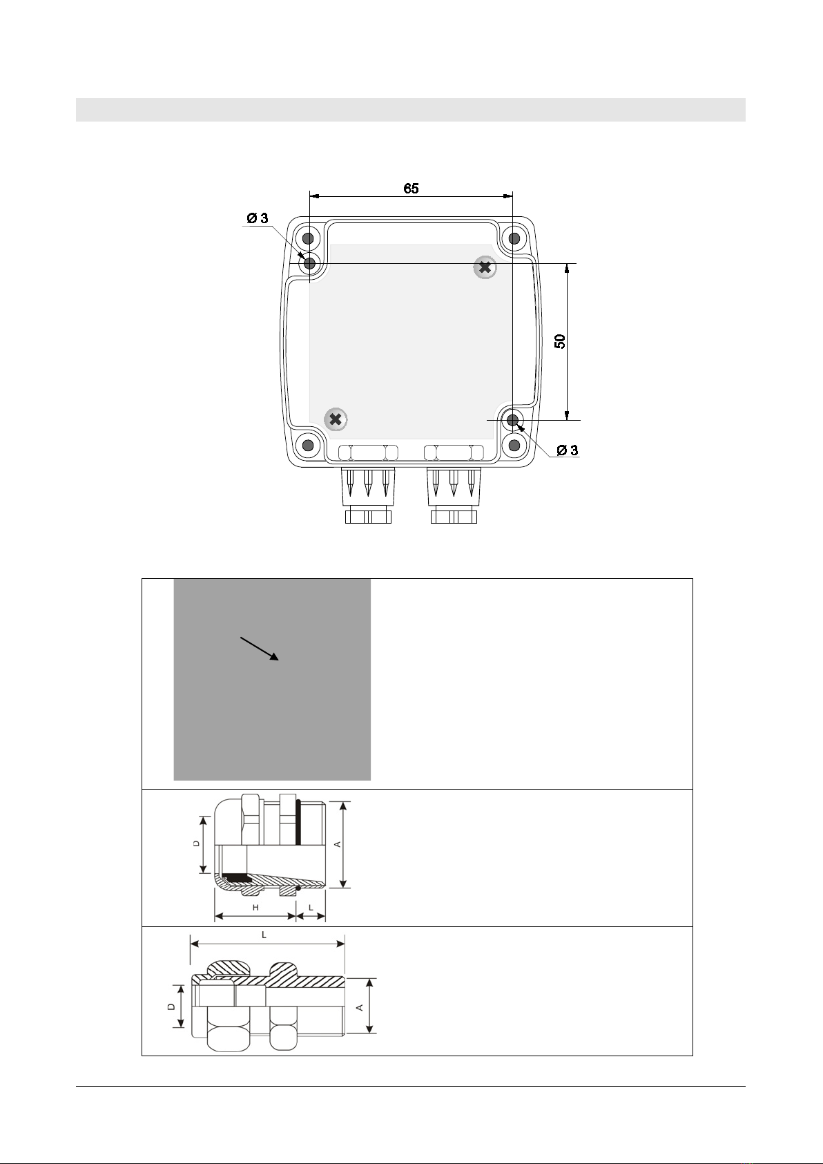
Electrical connections Screw terminal block, max 1.5 mm2 , PG9 cable gland
Connection to PC RS232 serial port (except HVAC40S17…)
RS485 serial port (only HVAC40S17…)
Can be connected to a USB port by using the optional CP27 (except
HVAC40S17…) or RS48 (only HVAC40S17…) adapter
Sensor operating
conditions -20…+80 °C.
The sensor shows best performance when operated in 20…80 %RH humidity
range. Long term exposure outside the indicated range (especially at high
humidity) may temporarily offset the sensor response.
The sensor is protected from water and dust.
Instrument operating
conditions -20…+60 °C / 0…95 %RH
Storage temperature -20…+80 °C
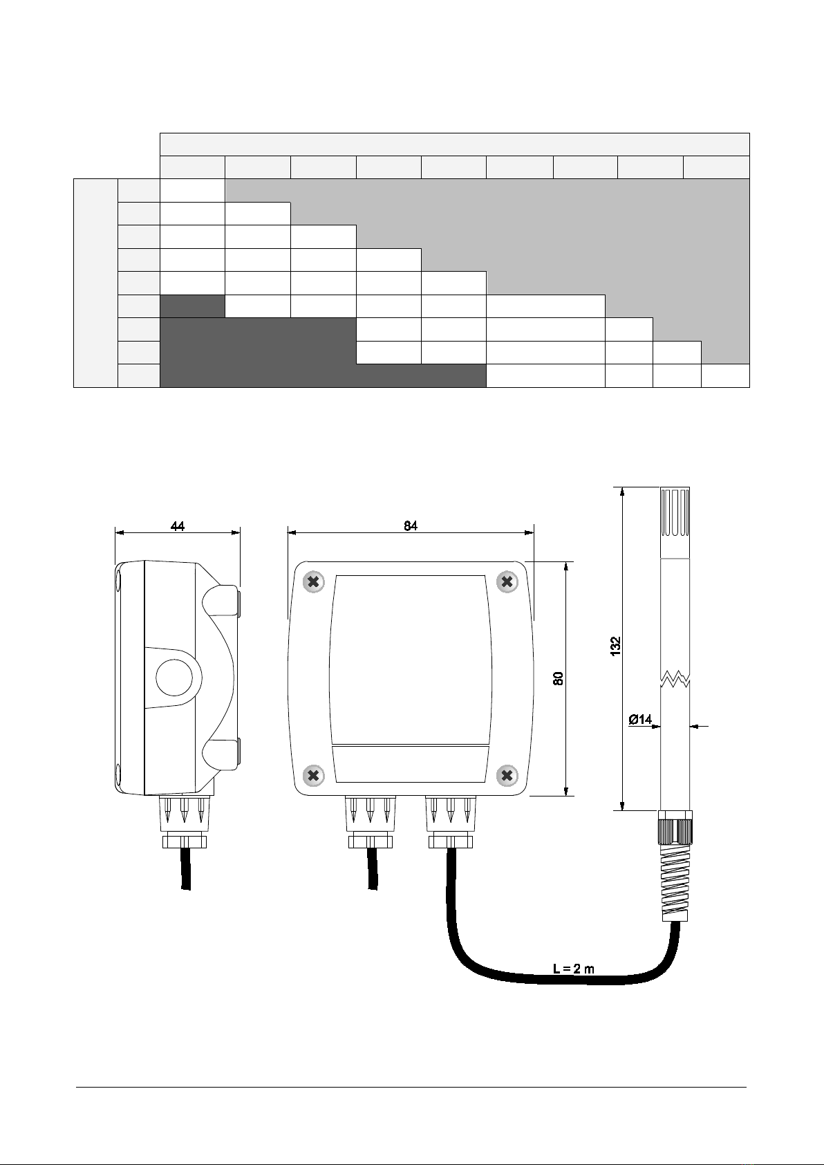
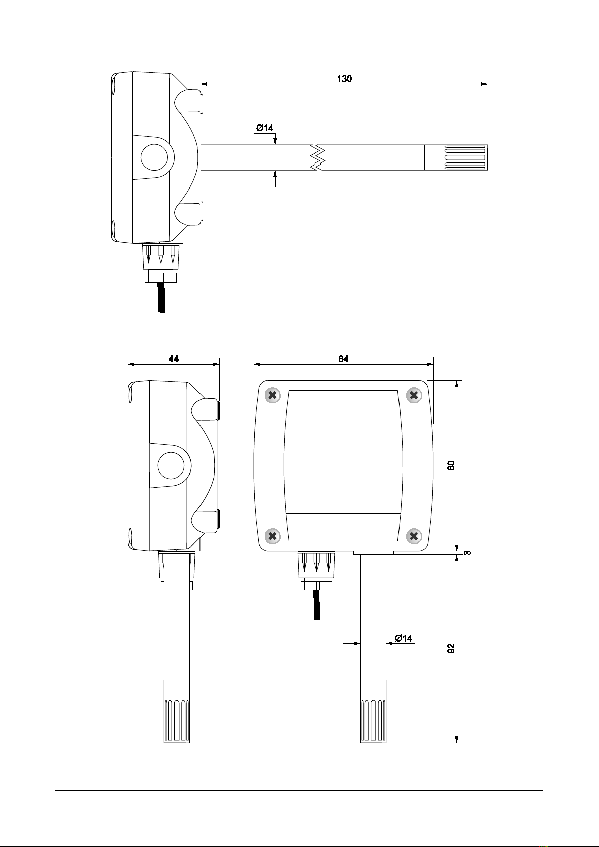
Housing dimensions 80 x 84 x 44 mm
Protection degree IP65

HVAC40… - 5-V1.1
Accuracy of Dew Point measurement (parameter calculated from the measurement of relative humid-
ity and temperature):
DP °C
-20 -10 0 10 20 30 40 60 80
Temperatur
e °C
-20 ≤±1
-10 ≤±1 ≤±1
0 ≤±1 ≤±1 ≤±1 DP LIMIT
10 ≤±3 ≤±1 ≤±1 ≤±1
20 ≤±4 ≤±2 ≤±1 ≤±1 ≤±1
30 ≤±3 ≤±1.5 ≤±1 ≤±1 ≤±1
40 NOT SPECIFIED
≤±2 ≤±1 ≤±1 ≤±1
60 ≤±5 ≤±2.5 ≤±2 ≤±1 ≤±1
80 ≤±4 ≤±2 ≤±1 ≤±1
For example, at 20 °C environmental temperature, the Dew Point value of 0 °C is measured with an ac-
curacy better than 1 °C.
DIMENSIONS (mm)
HVAC40…17TC.2

HVAC40… - 6-V1.1
HVAC40…17TO
HVAC40…17TV

HVAC40… - 7-V1.1
3INSTALLATION
By opening the lid, 3 mm diameter holes are available so to allow securing the base of
the instrument directly to a panel or to the wall.
The models with duct horizontal probe can be fixed by using the HD9008.31 flange, a
PG16 metal cable gland (∅10…14 mm) or a 3/8” universal biconical connection.
HD9008.31 Flange
PG16 metal cable gland
D = 10…14 mm
L = 6.5 mm
H = 23 mm
A = PG16
Universal biconical connector
L = 35 mm
D = 14 mm
A = 3/8"
HD9008.31

HVAC40… - 8-V1.1
Internally there are:
•the terminal header for connecting the power supply and the output;
•the RS232 serial connector (COM AUX, except HVAC40S17…);
•the dip switches for quick configuration.
•the buttons for the configuration via display (only HVAC40R17…).
Models with active analog output
(HVAC4017… and HVAC40V17…)
Models with 2-wire current output
(HVAC40A17…)
Models with digital RS485 output
(HVAC40S17…)
Models with relay switch output
(HVAC40R17…)

HVAC40… - 9-V1.1
3.1 ELECTRICAL CONNECTIONS
Models with active analog output
(HVAC4017… and HVAC40V17…)
Models with 2-wire current output
(HVAC40A17…)
Models with relay switch output (HVAC40R17…)
Models with digital RS485 output (HVAC40S17…)
In the RS485 connection, the instruments are connected in a sequence through a
shielded cable with twisted pair for signals and a third wire for the common. Line ter-
mination must be set at the two network ends.
The maximum number of devices that can be connected to the RS485 line (Bus) de-
pends on the load characteristics of the devices to be connected. The RS485 standard
requires that the total load does not exceed 32 unit loads. The load of an
HVAC40S17T… transmitter is equal to ¼ of unit load. If the total load is greater than
32 unit loads, divide the network into segments and add a signal repeater between a
Other sensors with
RS485 output
Termination
Termination
PLC, data logger or
RS485/USB or RS485/RS232
converter for PC

HVAC40… - 10 -V1.1
segment and the successive one. Line termination should be applied at both ends of
each segment.
The instrument has a built-in line termination that can be connected or removed
through a short jumper placed at the bottom of the electronic board. If the instrument
is the last or the first device of a network group, connect the termination by placing
the short jumper on the “RT ON” side. If the instrument is not at the end of a network
group, disconnect the termination by placing the short jumper on the side opposite to
“RT ON”.
The cable shield must be connected to both line ends. The cable should have the fol-
lowing features:
•Characteristic impedance: 120 ohm
•Capacity: less than 50pF/m
•Resistance: less than 100 ohm/km
•Gauge: 0,22 mm2(AWG24) at least
The cable maximum length depends on baud rate and cable characteristics. Typically,
the maximum length is 1200 m. The data line must be kept separated from any power
lines in order to prevent interferences on the transmitted signal.
3.2 CONFIGURATION DIP SWITCHES IN THE MODELS WITH ANALOG OUTPUT
HVAC4017T…, HVAC40A17T… and HVAC40V17T… transmitters have 4 preconfigured
temperature ranges for the analog output. In order to use a preconfigured tempera-
ture range, it is necessary to set the dip switch 1 to ON and set the temperature
range with the dip switches 2 and 3, according to the following table:
Dip switch
number Temperature
range
1 2 3
ON OFF ON 0…+50 °C
ON ON OFF -20…+50 °C
ON OFF OFF -20…+80 °C
ON ON ON 0…+80 °C
OFF N.U N.U Set via serial
In the HVAC4017T… and HVAC40V17T… models, with active analog output, a dip
switch is OFF when placed down; instead, it is ON if placed up. The dip switch 1 is on
the left.
In the HVAC40A17T… models, with 2-wire current output, a dip switch is OFF when
placed on the right; instead, it is ON if placed on the left. The dip switch 1 is at the
bottom.
If a temperature range other than the preconfigured ones is desired, it is necessary to
set the dip switch 1 to OFF and set the temperature range via COM AUX serial port.
The dip switch 4 is used to select the relative humidity (R.H.) or the dew point (D.P.)
measurement.

HVAC40… - 11 -V1.1
Dip switch
number Measurement
4
OFF R.H.
ON D.P.
3.3 CONFIGURATION DIP SWITCHES IN THE MODELS WITH RS485 DIGITAL OUTPUT
In the HVAC40S17… models, the transmitter Modbus address is equal to the sum of
the value set with the dip switches (value settable from 0 to 31) and the value set with
the serial command MA (value settable from 1 to 216, default = 1). By setting a dip
switch to ON (upwards), the following values are added to the address:
Dip switch number
1 2 3 4
ON 8 4 2 1
OFF 0 0 0 0
Example: if the dip switches 2 and 4 are set to ON, and the dip switches 3,5 and 6 are
set to OFF, the value set with the dip switches is 8+2=10. If the value set with the se-
rial command MA is 1 (default value), the transmitter Modbus address is 10+1=11.
The dip switches can be set even if the transmitter is powered, and the change is ef-
fective immediately.
Note: in the models with RS485 digital output, the selection of the relative humidity
or dew point measurement does not take place via a dip switch but via P0/P1 serial
commands.
3.4 CONFIGURATION DIP SWITCHES IN THE MODELS WITH RELAY OUTPUT
In the HVAC40S17… models, the dip switch 2 is used to select the relative humidity
(R.H.) or the dew point (D.P.) measurement.
Dip switch
number Measurement
2
OFF R.H.
ON D.P.
The dip switch 1 is not used.

HVAC40… - 12 -V1.1
3.5 CONFIGURATION VIA THE SERIAL PORT
1) HVAC4017T…, HVAC40A17T…, HVAC40V17T… and HVAC40R17T… models
Connect the COM AUX serial port of the instrument to the RS232 (via the RS27
cable) or USB (via the cable CP27) port of the PC. If the CP27 cable is used, in-
stall the USB drivers on your PC.
HVAC40S17T… models
Connect the RS485 output of the instrument to the RS232 (via a RS485/RS232
converter) or USB (via a RS485/USB converter, for example the RS48 cable) port
of the PC. If a RS485/USB converter is used, install the USB drivers on your PC.
2) On the PC, launch a standard serial communication software and set the baud rate
to 115200, the communication parameters to 8N2 and the COM port number to
which the instrument is connected.
3) Only for HVAC40S17T… models, power cycle the instrument and send the com-
mand @within 10 seconds from the instrument power on.
4) If necessary, send the CAL START command. The CAL START command enables
the use of some commands, specified in the tables below. The command
CAL START is automatically disabled after 5 minutes of inactivity or if the CAL END
command or an incorrect command is sent.
5) Send the setting or reading commands given below.
6) Only for HVAC40S17T… models, power cycle the instrument to restore the
MODBUS-RTU protocol.
Serial commands
Instrument general information
Command
Description
G0 Reads the instrument model
If the instrument has analog output, the instrument model is followed by the cur-
rent output setting (output lower analog value and temperature range associated
with the output)
Example of reply: HVAC40A17TC.2_4 -20 / 80 °C (output lower analog value = 4
mA, temperature range associated with the output = -20 / 80 °C
GF Similar to G0, but provides the configuration of the analog output set via serial
GS Similar to G0, but provides the configuration of the analog output set via dip
switches
G2 Reads the instrument serial number
G3 Reads the instrument firmware version
G4 Reads the instrument firmware date

HVAC40… - 13 -V1.1
Measurement
Command
Description
F0 Disable filtering of measurements (the last instantaneous measurement is pro-
vided)
F1 Enable filtering of measurements (default, a weighted average of the last meas-
urements is provided)
P0 Sets relative humidity as humidity measurement (default). Only HVAC40S17…
P1 Sets dew point as humidity measurement. Only HVAC40S17…
GP Reads the type of measurement set for humidity: relative humidity (0) or dew
point (1). Only HVAC40S17…
U3 Displays the temperature measurement on LCD
U4 Displays the humidity measurement on LCD (relative humidity or dew point de-
pending on the setting)
U5 Alternates the temperature and humidity measurements on LCD
UC Sets °C as temperature unit of measurement (default)
UF Sets °F as temperature unit of measurement
GU Reads the temperature unit of measurement
GM Reads the current measurement (not available in HVAC40S17… models)
The measurements are provided without the decimal point and in the sequence
temperature, relative humidity and dew point
Example of reply: 00230;C; 264;00032;Td C; (23.0 °C; 26.4 %UR; 3.2 °C Td)
Analog output (only HVAC4017…, HVAC40A17… and HVAC40V17… models)
Command
Description
U0 Sets 0…20 mA as current analog output
U1 Sets 4…20 mA as current analog output (default)
AIsnnn Associates the initial scale of temperature analog output with snnn (“s” is the
sign of the value) (*)
Default: -200 (=-20.0 °C)
ASsnnn Associates the full scale of temperature analog output with snnn (“s” is the sign
of the value) (*)
Default: +800 (=+80.0 °C)
AG Reads the temperature range associated with the analog output
Example of reply:
User Analog Scale: -200 / +800 C (-20.0…+80.0 °C)
KU Enables the temperature range set with the AIsnnn and ASsnnn commands
(*) The value must be written without the decimal point, even if it is not an integer value
(e.g., to associate 50.0 °C with the full scale of analog output, write AS+500). The value
is considered in the unit of measurement set in the instrument.
The temperature range set with the AIsnnn and ASsnnn commands is active only if it is
enabled with the KU command and the dip switch 1 is set to OFF.

HVAC40… - 14 -V1.1
Alarm (only HVAC40R17… models)
The commands starting with AW require prior sending of the CAL START command.
The threshold values refer to the relative humidity measurement or the dew point
measurement depending on the humidity measurement selected (via P0/P1 serial
commands for HVAC40S17… models, via dip switch for the other models).
Command
Description
AWSnSets the relay operating mode
n=0 ⇒Negative (NC contact is closed if no alarm, NO contact is closed if in alarm)
n=1 ⇒Positive (NO contact is closed if no alarm, NC contact is closed if in alarm)
Default: Negative
ARS Reads the relay operating mode
AWBnSets the buzzer activation status: n=0 ⇒OFF (default); n=1 ⇒ON
ARB Reads the buzzer activation status
AWAnSets the alarm activation status: n=0 ⇒OFF (default); n=1 ⇒ON
ARA Reads the alarm activation status
AWEnSets the alarm operating mode
n=0 ⇒Above threshold (alarm is on if measurement is greater than threshold 1)
n=1 ⇒Below threshold (alarm is on if measurement is less than threshold 1)
n=2 ⇒Outside thresholds (alarm is on if measurement is less than threshold 1
or greater than threshold 2)
Default: Above threshold
ARE Reads the alarm operating mode
AWT1snnn Sets the threshold 1 value to snnn (“s” is the sign of the value) (*)
Default: 300 (=30.0 %RH)
ART1 Reads the threshold 1 value
AWT2snnn Sets the threshold 2 value to snnn (“s” is the sign of the value) (*)
Default: 700 (=70.0 %RH)
ART2 Reads the threshold 2 value
AWHnnn Sets the hysteresis value to nnn (*)
Default: 100 (=10.0 %RH)
ARH Reads the hysteresis value
AWD1nnn Sets the alarm activation delay to nnn seconds (0… 600 s)
Default: 0
ARD1 Reads the alarm activation delay value
AWD2nnn Sets the alarm deactivation delay to nnn seconds (0… 600 s)
Default: 0
ARD2 Reads the alarm deactivation delay value
(*) The value must be written without the decimal point, even if it is not an integer value
(e.g., to set thresholds 1 to 15.0 %RH, write AWT1+150). In the case of the dew point
measurement, the thresholds and hysteresis values are considered in the unit of meas-
urement set in the instrument.

HVAC40… - 15 -V1.1
MODBUS (only HVAC40S17… models)
Command
Description
MA nnn Sets MODBUS address to nnn (default 1)
L1 Reads the MODBUS address
MB n Sets the MODBUS Baud Rate to:
9600 if n=0
19200 if n=1 (default)
38400 if n=2
57600 if n=3
115200 if n=4
L2 Reads the MODBUS Baud Rate
MP n Sets MODBUS parity and stop bits to:
8N1 if n=0 [No parity, 1 stop bit]
8N2 if n=1 [No parity, 2 stop bits]
8E1 if n=2 [Even parity, 1 stop bit] (default)
8E2 if n=3 [Even parity, 2 stop bits]
8O1 if n=4 [Odd parity, 1 stop bit]
8O2 if n=5 [Odd parity, 2 stop bits]
The number of bits is fixed to 8
L3 Reads the setting of MODBUS parity and stop bits
MW n Sets waiting time after MODBUS transmission to:
Immediate reception if n=0 (violates protocol)
Waiting 3.5 characters if n=1 (default, respects protocol)
L4 Reads the setting of waiting time after MODBUS transmission
Relative humidity calibration
The commands starting with Rrequire prior sending of the CAL START command.
Command
Description
GC Reads the calibration type in use: factory or user
GD Reads the factory calibration date (format yyyy/mm/dd hh.mm.ss)
GE Reads the user calibration date (format yyyy/mm/dd hh.mm.ss)
R0 vvv Calibrates the relative humidity lower point to the value vv.v %RH
The value must be between 300 (=30.0 %RH) and 350 (=35.0 %RH)
R1 vvv Calibrates the relative humidity upper point to the value vv.v %RH
The value must be between 730 (=73.0 %RH) and 770 (=77.0 %RH)
RU0 Uses the factory calibration
RU1 Uses the user calibration
RR Resets the user calibration to the factory calibration
RD yymmddhhmmss Sets the user calibration date

HVAC40… - 16 -V1.1
3.6 CONFIGURATION VIA THE INTERNAL BUTTONS (ONLY HVAC40R17…)
The upper button B1 allows scrolling the available operating parameters, while the
lower button B2 allows changing the setting of the selected parameter.
The function of a button depends on whether it is short or long pressed. To short
press a button, hold it down for about 1 second, until the power LED turns off. To long
press a button, hold it down for at least 3 seconds, until the power LED turns off and then
turns on again.
Long press the upper button B1 to enter the menu. Inside the menu, long press B1 to
scroll the available parameters. Below is the sequence of the operating parameters (in
brackets the indication that appears on the display) with the possible settings for non-
numerical parameters:
•Relay operating mode (SECU):
oNegative (NEG): NC contact is closed if no alarm, NO contact is closed if in alarm
oPositive (POS): NO contact is closed if no alarm, NC contact is closed if in alarm
•Buzzer activation (BEEP):
oOFF: buzzer disabled
oON: buzzer enabled
•Alarm activation (ALAR):
oOFF: alarm disabled
oON: alarm enabled
•Alarm operating mode (EDGE):
oAbove threshold (RISE): alarm is on if measurement is greater than threshold 1
oBelow threshold (FALL): alarm is on if measurement is less than threshold 1
oOutside thresholds (OUTS): alarm is on if measurement is less than threshold 1
or greater than threshold 2
•Threshold 1 (THR1): Value of the threshold for above (RISE) and below (FALL)
alarm operating modes; value of the lower threshold for outside thresholds (OUTS)
alarm operating mode.
•Threshold 2 (THR2): Value of the upper threshold for outside thresholds (OUTS)
alarm operating mode. The parameter appears only if the alarm operating mode
is set to OUTS.
•Hysteresis (HYST): Value of the hysteresis for above (RISE) and below (FALL)
threshold alarm operating modes. The parameter does appear if the alarm operat-
ing mode is set to OUTS.
•Alarm activation delay (T1): Value in seconds of the time delay for generating
the alarm. The alarm is generated only if the measurement exceeds the thresh-
old for more than the set time.
•Alarm deactivation delay (T2): Value in seconds of the time delay for deactivat-
ing the alarm. The alarm is deactivated only after the set time has elapsed from the
disappearance of the alarm condition.
Note: the threshold values refer to the relative humidity measurement or the dew
point measurement depending on the humidity measurement selected (via P0/P1 serial
commands for HVAC40S17… models, via dip switch for the other models).

HVAC40… - 17 -V1.1
Note: the EDGE, THR1, THR2, HYST, T1 and T2 parameters do not appear if the
alarm is set to OFF.
Changing non-numerical parameters:
•Select the parameter by using the button B1.
•Short press the button B2 to change the setting.
•Long press the button B1 to move to the next parameter.
Changing numerical parameters:
•Select the parameter by using the button B1.
•Short press the button B2 to change the sign.
•Long press the button B2 to select the first digit.
•Short press the button B2 to change the selected digit.
•Long press the button B2 to select the next digit.
•Repeat the above two steps until all the digits are set.
•Long press the button B1 to move to the next parameter.
While a parameter value is displayed, a short press of the button B1 will briefly show
the name of the currently selected parameter.

HVAC40… - 18 -V1.1
4ALARM OPERATING MODES (HVAC40R17…)
The operating modes shown are valid only for the HVAC40R17… models.
Above threshold (RISE): the alarm is turned on if the measurement is greater than
threshold 1 for more than T1 seconds. The alarm is turned off when the measurement
becomes less then threshold 1 minus the hysteresis for more than T2 seconds.
The up arrow on the left of the display is shown when this mode is selected.
Below threshold (FALL): the alarm is turned on if the measurement is less than
threshold 1 for more than T1 seconds. The alarm is turned off when the measurement
becomes greater then threshold 1 plus the hysteresis for more than T2 seconds.
The down arrow on the left of the display is shown when this mode is selected.
Outside thresholds (OUTS): the alarm is turned on if the measurement is greater
than threshold 2 or less than threshold 1 for more than T1 seconds. The alarm is turned
off when the measurement returs between the two thresholds for more than T2 seconds.
No hysteresis is applied to the thresholds.
The up and down arrows on the left of the display are shown when this mode is se-
lected.

HVAC40… - 19 -V1.1
When the measurement is in alarm, the red LED lights up, the buzzer is on (if ena-
bled) and the relay is switched (depending on the chosen relay operating mode).
While in alarm, the buzzer can be stopped (only for the current event) by short press-
ing the button B1.
The alarm is disabled while in the configuration menu.

HVAC40… - 20 -V1.1
5MODBUS-RTU (HVAC40S17…)
The default communication parameters are 19200, 8E1 and can be changed with the
serial commands MB/MP.
The instrument address (default 1) can be changed with the serial command MA.
The MODBUS registers available are shown below.
Input Registers
Register
number
Register
address Datum Format
1 0 Temperature in °C (x10) 16-bit integer
2 1 Temperature in °F (x10) 16-bit integer
3 2 Relative Humidity in % (x10) 16-bit integer
4 3 Dew Point in °C (x10) 16-bit integer
5 4 Dew Point in °F (x10) 16-bit integer
6 5 Status register
Bit 0 = 1 ⇒temperature measurement error
Bit 1 = 1 ⇒relative humidity measurement error
Bit 2 = 1 ⇒dew point measurement error
Bit 3 = 1 ⇒configuration data error
16-bit integer
Table of contents
Other GHM Transmitter manuals
Popular Transmitter manuals by other brands

Mhouse
Mhouse STX2 Installation and use instructions and warnings

HK Instruments
HK Instruments DPT-MOD Series installation instructions

ATA
ATA SecuraCode PTX-4 instruction manual

Labom
Labom PASCAL Ci4 LEVEL operating instructions

rada
rada A-BR02 Quick installation guide

Johnson
Johnson VIKING 6N2 Assembly and operating instructions

AFi
AFi MT-740C instruction manual

Lectrosonics
Lectrosonics UT instruction manual

Jung
Jung 41F Series operating instructions

Emerson
Emerson Rosemount 2088 quick start guide

Dwyer Instruments
Dwyer Instruments ISDP series Specifications-installation and operating instructions

CYP
CYP CH-1107 TX Operation manual