Seek Thermal InspectionCAM User manual

Seek Inspection Camera –Quick Start Guide REV4
Seek InspectionCAM
Quick Start Guide
Welcome to Seek Thermal’s Seek Inspection Camera Quick Start Guide. This guide covers how to get the
Seek Inspection Camera (InspectionCAM) imaging and some general recommendations for first article
inspection setups. For a more detailed guide, please refer to the Seek Inspection Camera User Manual.
Start Imaging
Required hardware: Windows 10 or 11 PC
1) Remove the InspectionCAM from the box; there is a Welcome Card, Focus Tool, USB Stick, and
USB-C to USB-A Cable in the box as well.
2) Take the USB Stick and plug it into the Windows PC and run the Seek Inspection Camera
Viewer.msi installer.
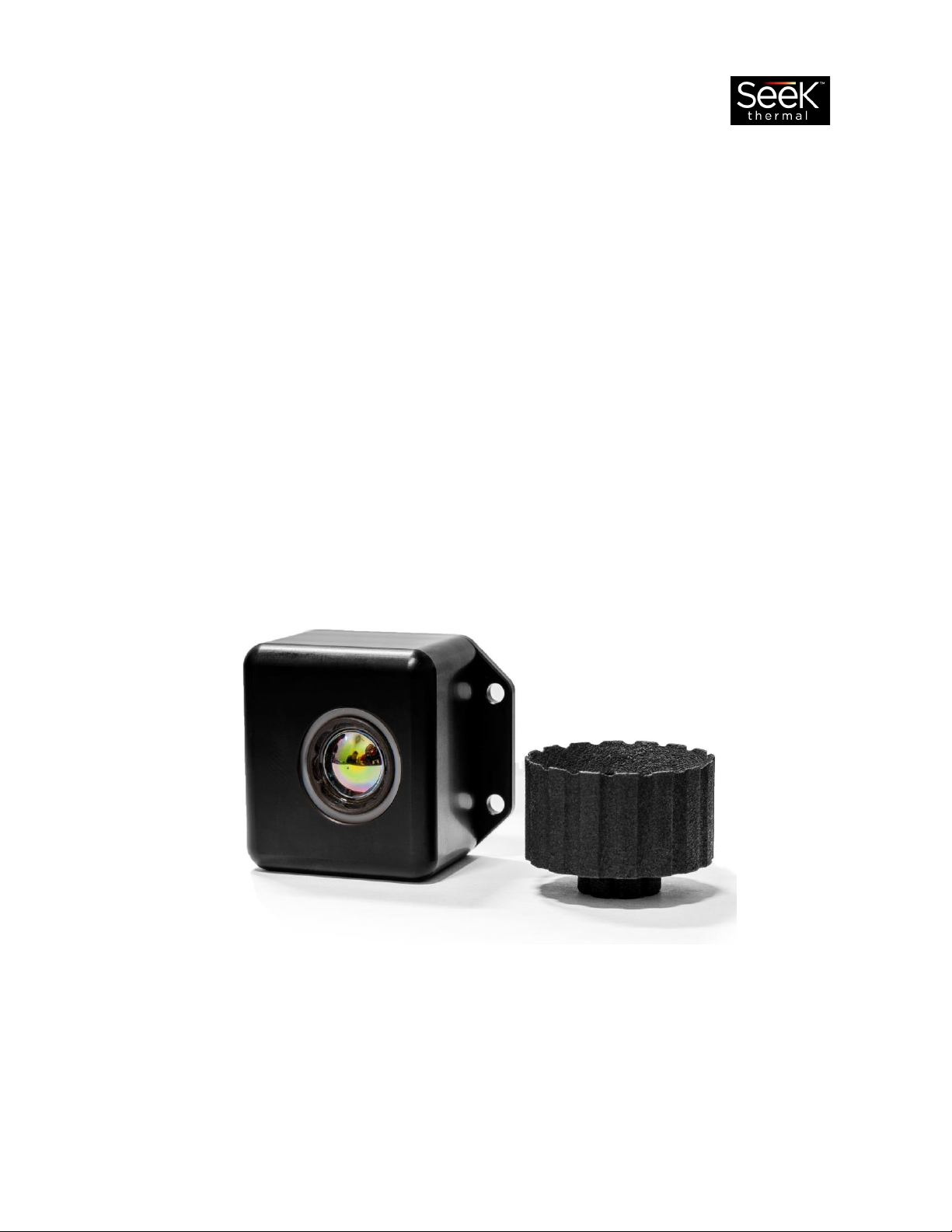
3) There are mounting holes on the back of the camera and with the removal of the black cap on
the bottom of the camera an additional ¼”-20 mounting hole can be used. Mount the camera
into position.
Cosmetic Cap
¼”-20 Mounting Hole
4) Use the USB-C cable to plug the camera into the PC and open the Seek Inspection Camera
Viewer Software.

Seek Inspection Camera –Quick Start Guide REV4
5) The camera serial number (SN) will show up in the Cameras: list section in the upper left corner
of the software. Selecting the SN will turn it blue, then push the start button to image.
6) By default, the camera is focused to infinity; use the Focus Tool to focus the camera on objects
at close distances. Insert the Focus Tool int the grooves around the inside of the lens and rotate
the tool counterclockwise to focus closer and clockwise to focus farther away.
Insert the Focus Tool and turn counterclockwise to focus closer
Object at 200mm away from camera
Camera focused for infinity
Object at 200mm away from camera
Camera focused for 200mm
WARNING: Unscrewing the lens too many times can remove the lens from the housing. Insert the lens
back into the housing and screw the lens clockwise if lens comes out. To avoid accidental lens removal
do not try to focus on objects closer than 40mm away from the camera lens.

Seek Inspection Camera –Quick Start Guide REV4
Commonly Used Setups and Features in Inspection Software
AGC Modes
Toggling between the Legacy Histogram (LEGACY_HISTEQ) and LINEAR AGC modes can help show the
general layout and heatmap of an object.
LEGACY_HISTEQ
LINEAR
Seek Inspection Camera –Quick Start Guide REV4
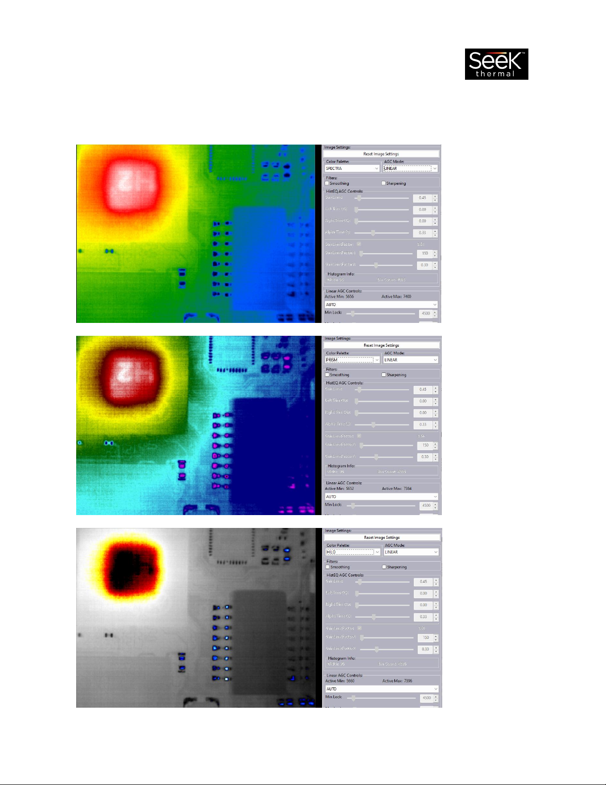
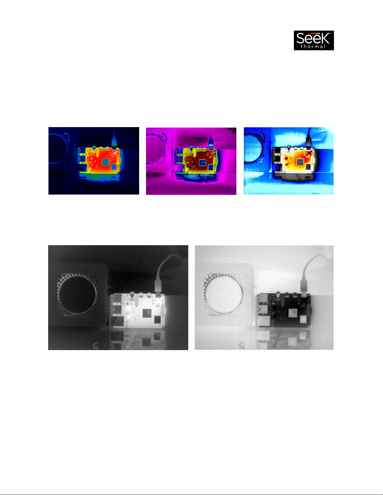
Color Palettes
For fast analysis try toggling between SPECTRA, PRISM, and HILO to show where warmer and cooler
temperatures and areas of interest are on a device.
SPECTRA
PRISM
HILO

Seek Inspection Camera –Quick Start Guide REV4
For more detailed analysis toggle between the WHITE and BLACK color palettes to show details other
palettes sometimes blur together.
BLACK
WHITE
Seek Inspection Camera –Quick Start Guide REV4
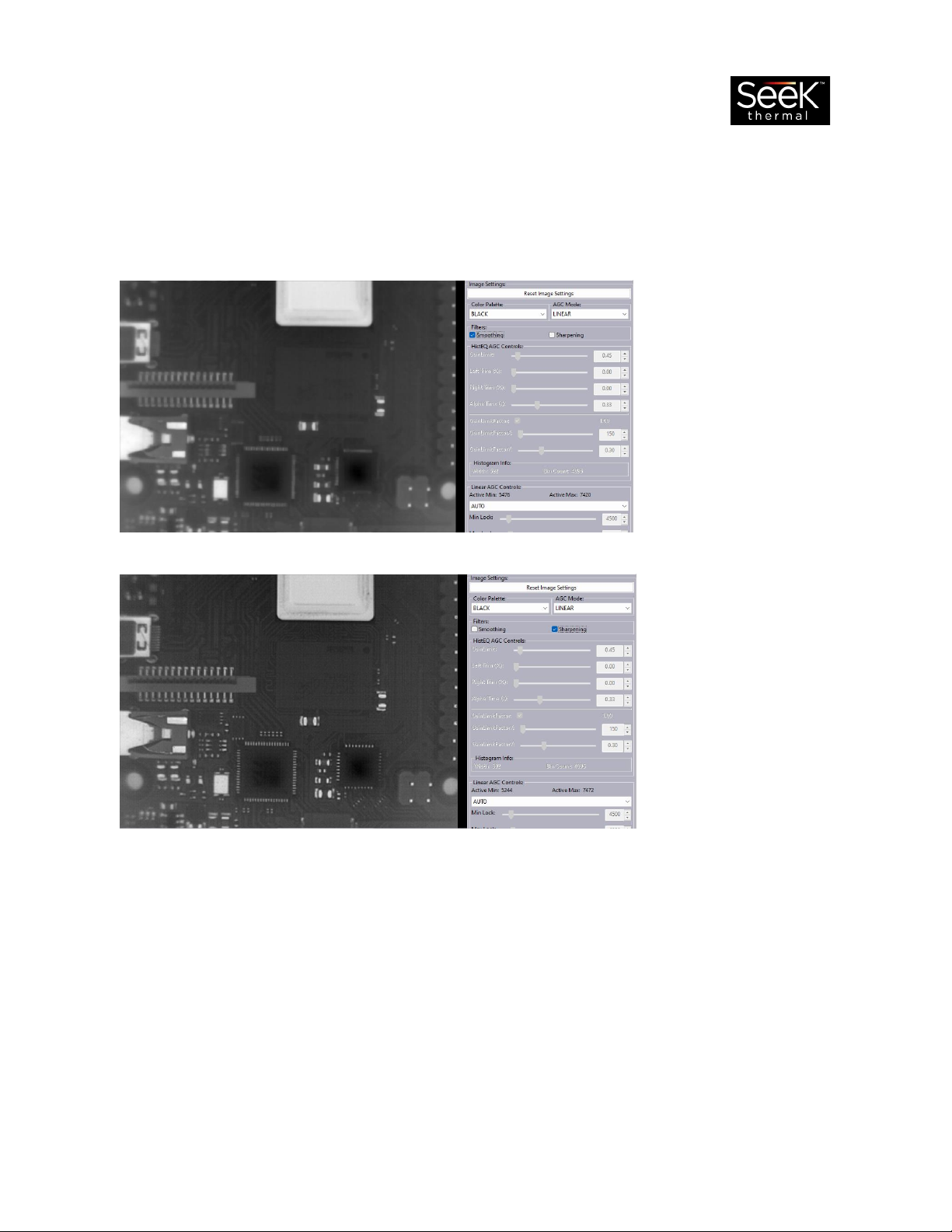
Sharpening and Smoothing Filters
While in the WHITE and BLACK color palettes, use the sharpening and smoothing filters to adjust the
image clarity. Sharpening will try to highlight edges in the image. Smoothing will try to smooth the
image out; however, this may also smooth out some details as well.
Sharpening Off
Smoothing On
Sharpening On
Smoothing Off
Most inspection installations use the common setups, settings, and features in the Seek Thermal
Inspection Camera Viewer software reviewed in this guide. Toggling between these different Color
Palettes, AGC modes, and Filters can highlight and accentuate image data and details. For a more
extensive overview of the Seek Inspection Camera and the Seek Inspection Camera Viewer software,
please see the Seek Inspection Camera User Manual.
Seek Inspection Camera –User Manual REV4
Seek Inspection Camera
User Manual

Seek Inspection Camera –User Manual REV4
Table of Contents
What’s in the Box..........................................................................................................................................3
What’s Required ...........................................................................................................................................4
Register the Inspection Camera....................................................................................................................4
Camera Mounting Options ...........................................................................................................................4
Dimensional Drawing....................................................................................................................................5
Install the Seek Inspection Camera Viewer ..................................................................................................5
Inspection Camera Viewer Layout................................................................................................................6
Camera Connection and Information ...........................................................................................................7
Cameras ....................................................................................................................................................7
Camera Control.........................................................................................................................................7
Camera Info...............................................................................................................................................7
General Settings and Controls ......................................................................................................................7
Temperature Offset ..................................................................................................................................8
Temperature Units....................................................................................................................................8
Shutter Control .........................................................................................................................................8
Timestamp Control & Frame Info .............................................................................................................8
On Screen Display (OSD)...........................................................................................................................8
Custom Drawn Area..................................................................................................................................9
Image Settings and Controls .........................................................................................................................9
Image Settings...........................................................................................................................................9
Color Palette ...........................................................................................................................................10
AGC Mode...............................................................................................................................................10
Filters: Smoothing & Sharpening ............................................................................................................11
Linear AGC Controls................................................................................................................................12
Active Min & Active Max.....................................................................................................................12
HistEQ AGC Controls ...............................................................................................................................14
Customize or Integrate InspectionCAM......................................................................................................15

Seek Inspection Camera –User Manual REV4
What’s in the Box
USB STICK includes User Manual, Quick Start Guide, Camera
Warranty Policy, Seek Inspection Camera Viewer Software
Installer
FOCUS TOOL used to focus the camera on objects near and far
away. The cameras default focus is set to distance of infinity.
Turning the lens counterclockwise will focus on objects closer to
the camera, while turning the lens clockwise will focus on
objects farther away.
WARNING: Unscrewing the lens too many times can remove the
lens from the housing. Insert the lens back into the housing and
screw the lens clockwise if lens comes out. To avoid accidental
lens removal do not try to focus on objects closer than 40mm
away from the camera lens.
USB Cable 2-meter USB-C male to USB-A male cable.
InspectionCAM Seek Inspection Camera
Seek Inspection Camera –User Manual REV4
What’s Required
A Windows 10 or 11 PC is required to run the Seek Inspection Camera Viewer software.
Register the Inspection Camera
It is very important to register the Seek Inspection Camera right away. This will help track the warranty
of the camera, but more importantly this is how to stay up to date with all the latest software releases
and future improvements to the Seek Inspection Camera system. To register the camera, please visit
https://www.thermal.com/register.
Camera Mounting Options
There is a ¼”-20 mounting hole on the bottom of the camera. To access the hole, simply remove the
cosmetic cap from the bottom of the housing.
Cosmetic Cap
¼”-20 Mounting Hole
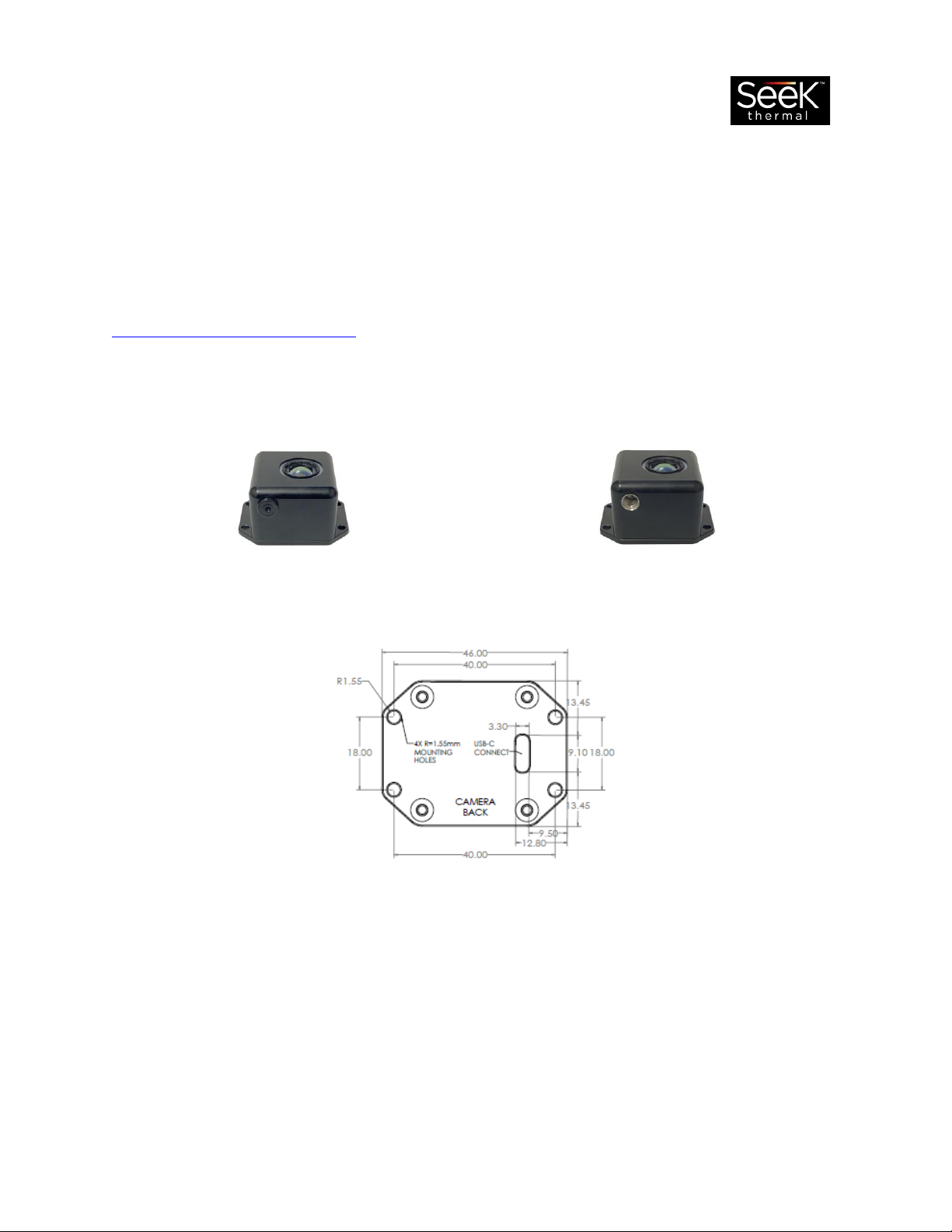
An additional mounting option, there are four mounting holes on the back plate on the camera.
Back Mounting Plate pattern and dimensions in millimeters (mm)
Seek Inspection Camera –User Manual REV4
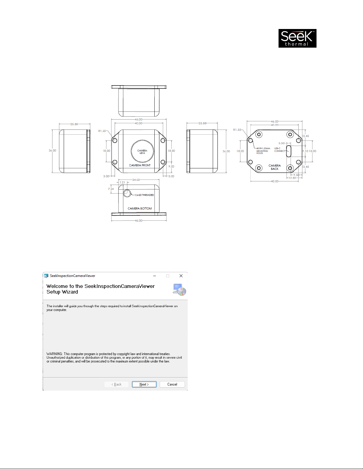
Dimensional Drawing
The drawing below represents the InspectionCAM’s full product dimensions in millimeters (mm).
Install the Seek Inspection Camera Viewer
1) On the USB Stick inside of the Inspection Camera box is the Seek Inspection Camera software
installer. Plug the USB stick into the Windows PC and double click on the
SeekInspectionCameraViewerInstaller.msi file to start the installation.
2) Push the Next button, chose a location on the PC to install the software, and hit Next to
continue to run through the rest of the installation.
Seek Inspection Camera –User Manual REV4
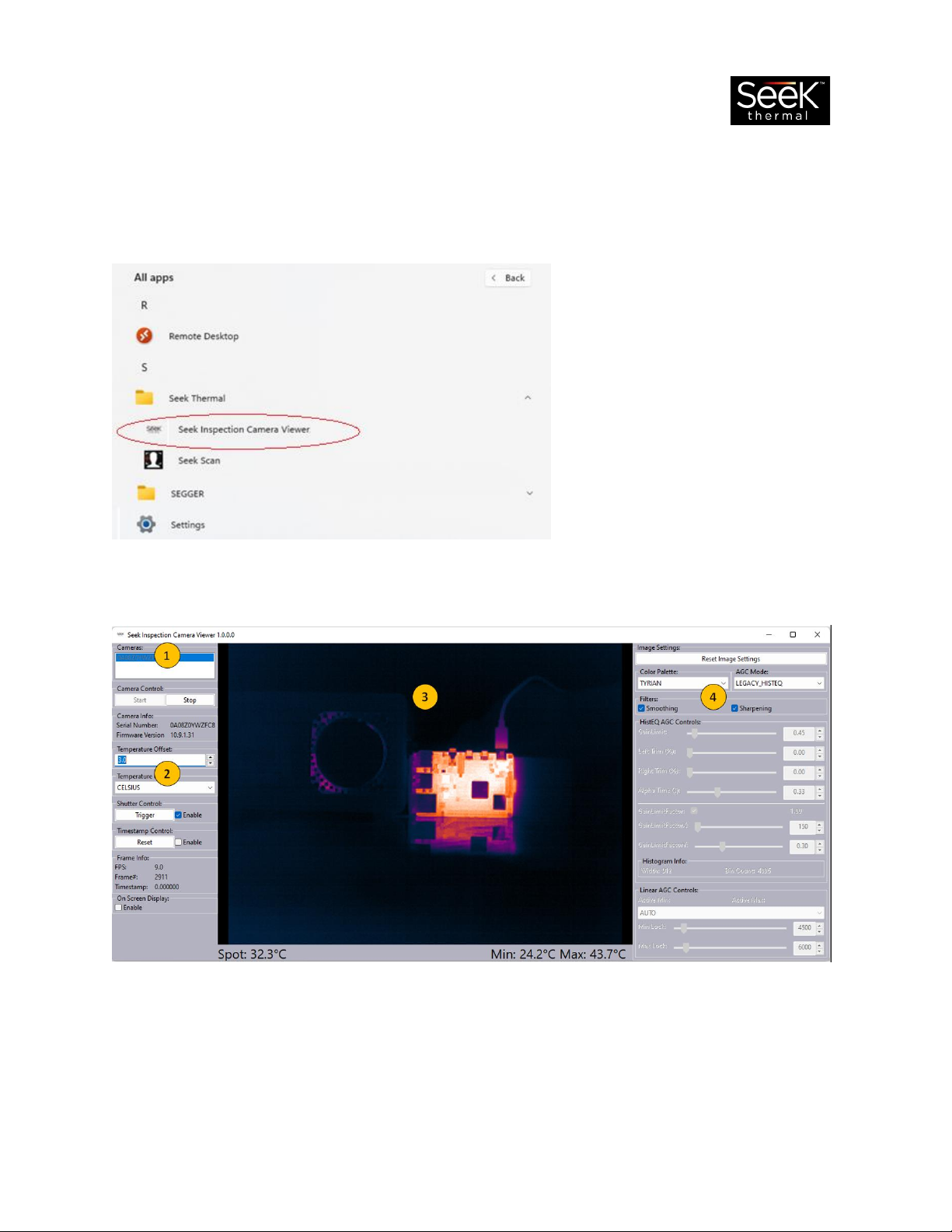
3) Once installed, navigate to the software in the Windows PC Apps list under Seek Thermal ->
Seek Inspection Camera Viewer and open the software.
4) Plug in the InspectionCAM using the USB cable, select the camera from the Cameras: list and
push the Start button connect and image.
Inspection Camera Viewer Layout
The Seek Inspection Camera Viewer software can be broken down into four main sections:
1. Camera Connection and Information
2. General Settings and Controls
3. Imagery and Temperature Data
4. Image Settings and Controls

Seek Inspection Camera –User Manual REV4
Camera Connection and Information
This section of the software allows you to select the camera from the camera list and open a data
connection to the camera. The camera serial number and firmware version are also visible in this area.
Cameras
This is a list of the available and recognized Seek Thermal devices by Serial Number. Plug in the
InspectionCAM and select the camera from the list, which will be highlighted in blue once selected.
Press the Start button in the Camera Control section to connect and image the Seek Thermal camera.
Camera Control
Connect to and image a selected (blue) camera from the Cameras: list section.
•Press the Start button to connect to the selected camera and start imaging.
•Press the Stop button to disconnect and stop imaging from the connected camera.
Camera Info
This contains the camera serial number and the current firmware version.
General Settings and Controls
These features allow the user to make setting adjustments and selections in the software. Controls and
settings for temperature, shutter, on screen displays (OSD), and timestamp are available on the left side
of the software.

Seek Inspection Camera –User Manual REV4
Temperature Offset
A global temperature offset can be added or subtracted to the temperature values displayed in the
application. This is useful in fine tuning or adjusting the camera temperature data in various installations
and setups. Distance and lens focus position can affect the temperature readings from the camera.
Temperature Units
Select from 3 different temperature units: Celsius, Fahrenheit, Kelvin.
Shutter Control
Control the state of the camera’s automatic shutter or trigger shutter events manually at any time.
•The Enable checkbox
oWhen checked the camera runs in Automatic Shutter mode.
oWhen unchecked the camera runs in Manual Shutter mode.
•Press the Trigger button to trigger a shutter event at any time.
Note: It is highly recommended that the Automatic Shutter be Enabled at all times. This will correct any
drift the pixels in the array may experience.
Timestamp Control & Frame Info
The Inspection Cam Viewer allows for the user to track and manage digital time stamp. Frame
information like current system frame rate and the current frame number are displayed in the Frame
Info section.
•Enable or disable via the Enable checkbox.
•Reset the timestamp by selecting the Reset button.
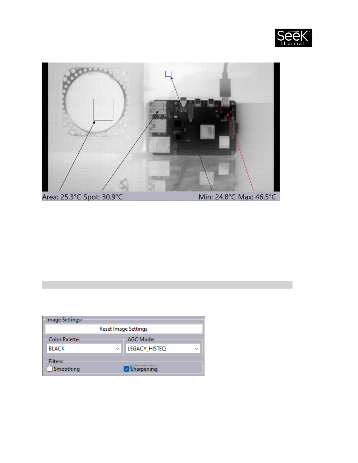
On Screen Display (OSD)
The On-Screen Display section allows the user to turn on or off the visual boxes representing the
temperature values displayed on the bottom of the software. When in BLACK mode the boxes will be
colored as follows:
Center Spot (Spot) –Black
Minimum Spot (Min) –Blue
Maximum Spot (Max) –Red
Drawn Area (Area) –Black
Seek Inspection Camera –User Manual REV4
Custom Drawn Area
When the On-Screen Display (OSD) is enabled, the user can draw an area in the image and display the
average temperature in the custom drawn area. Use the mouse to draw and remove the custom area.
1st Mouse Click –Sets upper left corner position of Drawn Area
2nd Mouse Click –Sets lower right corner position of Drawn Area
3rd Mouse Click Inside the Area Box –Removes the Drawn Area
NOTE: The On-Screen Display must be enabled to add, remove, and see the custom drawn area.
Image Settings and Controls
Image Settings
Press the Reset Image Settings button to restore the default image settings for the InspectionCAM.
Seek Inspection Camera –User Manual REV4
Color Palette
There are several color palettes to choose from in the color palette drop down list. For inspection
applications Seek recommends switching between a few different palettes to see different contrasts.
For faster high-level analysis Seek recommends toggling between the SPECTRA, PRISM, and HILO color
palettes. This can help quickly identify area of interest on a device.
SPECTRA
PRISM
HILO
Toggle between the WHITE and BLACK palettes to show more precision and detail in areas of interest.
WHITE
BLACK
AGC Mode
There are three automatic gain control (AGC) algorithms that can be used to image the camera data:
LEGACY_HISTEQ, LINEAR, and HISTEQ.

Seek Inspection Camera –User Manual REV4
LEGACY_HISTEQ is a fixed histogram based AGC
algorithm. Different color palettes will highlight
and focus on warmer parts of the board and
drowned out the background when big
temperature gaps occur. The LEGACY_HISTEQ
AGC Mode is often used in inspection
applications.
LINEAR is a linearly based AGC algorithm. Linear
AGC Mode can be run in four different ways:
AUTO, LOCKED, MIN LOCK, and MAX LOCK. This
will make a linear mapping from the lowest to
highest temperature in the scene for image
colorization. The Linear AGC Mode is often used
in inspection application.
HISTEQ is an adjustable histogram based AGC
algorithm with various controls and parameters
to adjust how the algorithm performs. Different
color palettes can bring out low temperatures
while looking at high temperatures at the same
time.
Filters: Smoothing & Sharpening
The software has two filters that can be enabled and disabled: Smoothing and Sharpening.
Smoothing will try to smooth
out noise in the image but can
also hide details in the image.
Sharpening will give the image
more crisp, pixelated edges but
can introduce more noise into
the image.
Seek Inspection Camera –User Manual REV4
Linear AGC Controls
The LINEAR AGC Mode will make linear mapping of the coldest point in a scene to the warmest. This is
often useful in electronic component analysis. Along with the LINEAR imaging algorithm, there are
various controls given to adjust algorithm and imagery: AUTO, LOCKED, MIN LOCK, and MAX LOCK.
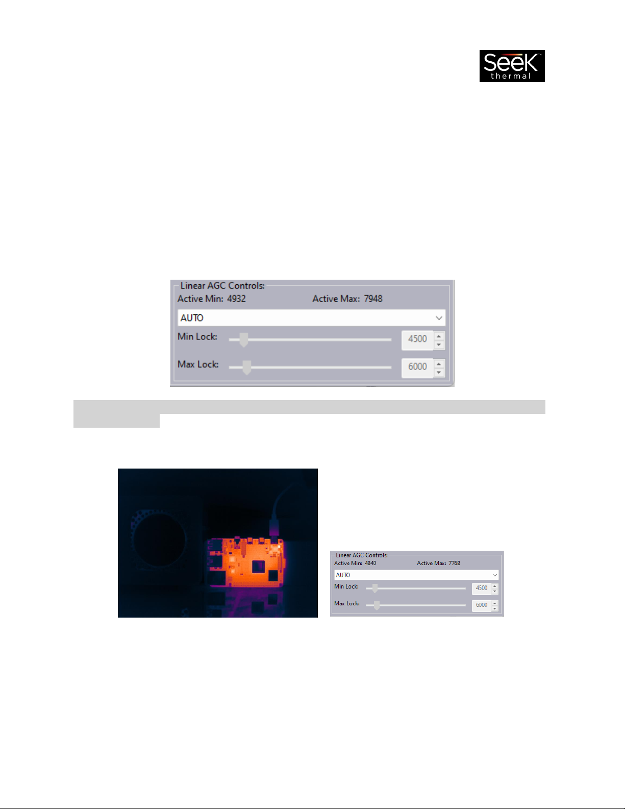
Active Min & Active Max
At the top of the Linear AGC Controls there are two fields displaying the active minimum and maximum
count values of the active image. These can be used to help tune the locking minimum and maximum
values for the linear AGC algorithm to focus on specific objects of temperature in the image.
Note: Count values correspond to active colorized heat imagery data and not the absolute temperature
of the object itself.
AUTO automatically sets the
minimum and maximum count values
in the linear AGC algorithm color
mapping.

Seek Inspection Camera –User Manual REV4
MIN LOCK sets the minimum count
value in the linear AGC algorithm color
mapping. This can often be used to
hide cooler components and objects
in the image.
MAX LOCK sets the maximum count
value in the linear AGC algorithm color
mapping. This can often be used to
bring in cooler components and
objects in the image.
LOCKED sets a minimum and
maximum count values used in the
linear AGC algorithm color mapping.
This can often be used to focus on
specific components of certain
temperatures in the image.

Seek Inspection Camera –User Manual REV4
HistEQ AGC Controls
Seek Thermal Inspection Camera Viewer offers one more AGC algorithm for imaging, HISTEQ. This is an
adjustable histogram algorithm.
NOTE: The histogram algorithm is tuned by default for imaging the camera in general situations both
indoors and outside.
Default HistEQ AGC Controls
Tuned HistEQ AGC Controls
GainLimit sets how much gain is used in the Histogram algorithm colorization. Gain can sometimes be
compared to ‘thermal sensitivity’. Increasing the gain limit can increase the thermal contrast but can
also introduce noise into an image.
Left Trim trims the bottom of the histogram algorithm making colder parts of the image fade in detail
and contrast.
Right Trim trims the top of the histogram algorithm making warmer parts of the image fade in detail and
contrast.
Table of contents


