SEER SFL-MP10S User manual
Shanghai Seer Intelligent Technology Corporation.
www.seer-group.com AMR.AI
User Guide
SFL-MP10S


SMF-MP10S User guide V1.1 Shanghai Seer Intelligent Technology Corporation
Thanks for your purchase.
Only those who have received training and qualified correspondingly are allowed to use
this product.
This document includes precautions that shall be followed to ensure personal safety and
protect this product.
Disclaimer
All contents of this document have been verified and confirmed to be as accurate, reliable
and complete as possible, but there is no guarantee that all contents are consistent with
the product.
Technical data may be changed without further notice.
This document is copyrighted solely by Shanghai Seer Intelligent Technology Corporation
and may not be reproduced or distributed in any form by any organization or individual
without our written permission. If quoted, the source must be indicated, and this document
shall not be quoted, abridged or modified contrary to the original intent.
Shanghai Seer Intelligent Technology Corporation does not make any express or implied
warranties for this document and its contents.
Shanghai Seer Intelligent Technology Corporation reserves the right of modification and
final interpretation of the terms of this Disclaimer.

Contents
1. Foreword........................................................................................................................... 1
1.1 Reading Tips........................................................................................................................1
1.2 Use Prohibitions..................................................................................................................1
2. Safety................................................................................................................................ 2
2.1 Types of Safety Information ...............................................................................................2
2.2 General Safety Precautions ................................................................................................2
2.3 Safety Instructions ..............................................................................................................3
2.3.1 Qualification Requirements for Personnel..............................................................3
2.3.2 Running Safety ........................................................................................................3
2.3.3 Load Safety..............................................................................................................4
2.3.4 Parking Safety..........................................................................................................4
2.3.5 Safe Avoidance Range .............................................................................................5
2.4 Battery Safety .....................................................................................................................5
2.5 Risk Assessment..................................................................................................................6
2.6 Residual Risk .......................................................................................................................6
2.7 Environmental Safety .........................................................................................................6
2.7.1 Noise........................................................................................................................6
2.7.2 Scrap Disposition.....................................................................................................7
3. Product Introduction.......................................................................................................... 8
3.1 Overview.............................................................................................................................8
3.2 Product Dimensions............................................................................................................8
3.2.1 Dimensions of Robot...............................................................................................8
3.2.2 Coordinate System of gyroscope ..........................................................................10
3.3 Main Labels.......................................................................................................................12
3.3.1 Precautions............................................................................................................12
3.3.2 Nameplate.............................................................................................................13
3.3.3 Daily Maintenance of Robot..................................................................................14
3.4 Configuration of Body.......................................................................................................14
3.5 Operation Panel................................................................................................................15
3.6 Audio/Video System .........................................................................................................16
3.6.1 Ambient Light ........................................................................................................16
3.6.2 Searchlight.............................................................................................................17
3.7 Technical Parameters .......................................................................................................17
3.8 Software Functions...........................................................................................................19
3.9 Network Requirements and Configuration ......................................................................19

4. Start to Use ..................................................................................................................... 20
4.1 Accompanied Articles .......................................................................................................20
4.2 Startup of Robot ...............................................................................................................20
4.3 Shutdown of Robot...........................................................................................................20
5. Battery and Charging ....................................................................................................... 21
5.1 Battery Parameters...........................................................................................................21
5.2 Parameters of Charger......................................................................................................22
5.3 Charging of Robot.............................................................................................................24
5.4 Storage of Battery.............................................................................................................24
6. Navigation and Control System ........................................................................................ 25
6.1 System Overview ..............................................................................................................25
6.2 User Input Information.....................................................................................................26
6.3 Global Path Planning.........................................................................................................27
6.4 Local Path Planning...........................................................................................................28
6.5 Task Planning and Action Planning...................................................................................29
6.6 Obstacle Detection ...........................................................................................................30
6.6.1 Navigation Laser....................................................................................................31
6.6.2 Obstacle Avoidance Laser .....................................................................................36
6.7 Localization.......................................................................................................................39
6.8 Motor drivers and motors ................................................................................................40
7. Debugging ....................................................................................................................... 41
7.1 Connect the Robot............................................................................................................41
7.2 Map Building and Editing..................................................................................................42
7.3 Path Navigation and Obstacle Verification.......................................................................45
7.4 Establishment and Configuration of Workstation (AP) with Fork Action.........................46
7.4.1 Workstation (AP)...................................................................................................46
7.4.2 Special Workstation (CP, or Charging Point) .........................................................47
7.4.3 Work Path..............................................................................................................47
7.5 Navigate the Path to Specified Point and Execute the Corresponding Action .................49
7.6 Control the Rising/Dropping of the Fork via Upper Computer.........................................51
7.7 Recognition Function........................................................................................................52
7.7.1 Pallet Recognition .................................................................................................52
7.7.2 Material Cage Recognition ....................................................................................54
7.8 Error Code.........................................................................................................................56
8. Applications..................................................................................................................... 57
9. Product Maintenance....................................................................................................... 58

9.1 Maintenance Instructions.................................................................................................58
9.2 Periodic Maintenance.......................................................................................................59
9.3 List of Quick-wear Parts....................................................................................................65
9.4 Cleaning ............................................................................................................................65
9.4.1 Floor Cleaning........................................................................................................65
9.4.2 Robot Cleaning ......................................................................................................66
9.4.3 Laser Cleaning .......................................................................................................67
9.5 Storage..............................................................................................................................67
9.5.1 Storage of Robot ...................................................................................................67
9.5.2 Storage of Charger ................................................................................................68
10. Loading/Unloading and Transportation........................................................................... 69
11. Load Center ................................................................................................................... 71
12. Software Update............................................................................................................ 72
Appendix I Hydraulic Schematic Diagram.............................................................................. 75
Appendix II Electrical Schematic Diagram of SMF-MP10S ...................................................... 76

1. Foreword
SMF-MP10S User guide V1.1 Shanghai Seer Intelligent Technology Corporation 1
1. Foreword
1.1 Reading Tips
Before using the robot, always read the User Guide carefully.
Do not disassemble or assemble the SMF-MP10S without authorization.
Please pay attention to the safety warnings involved in the User Guide.
If there is any abnormal problem with the robot, please contact the manufacturer promptly.
If you smell an unusual odor when using the robot, please stop the robot immediately, turn
it off and remove the batteries.
The User Guide is not a substitute for the Technical Agreement.
1.2 Use Prohibitions
It is prohibited to use it in an outdoor environment.
It is prohibited to use it in an environment that strongly interferes with navigation
equipment.
It is prohibited to use it in an environment full of dust, powder, and other explosive
hazards.
It is prohibited to use it in an environment with high salt content (marine climate).
It is prohibited to use it in extremely bad environments (extreme weather, cold storage,
and strong magnetic fields etc.).
It is prohibited to carry inflammable and explosive materials.
It is prohibited to carry liquid objects.
It is prohibited to run on uneven, obstructed or stepped ground.
It is prohibited to turn in place on the ramp.
It is prohibited to carry people.
It is prohibited to run it with the load on the shell.
2. Safety
SMF-MP10S User guide V1.1 Shanghai Seer Intelligent Technology Corporation 2
2. Safety
Please read this section before starting and running SMF-MP10S.
Notice
●We will
not responsible for any problems caused by damage, replacement or
modification of SMF-MP10S or its accessories in any way.
●We will not responsible for any damages to SMF-MP10S, accessories or any other
equipment due to programming errors or faults.
2.1 Types of Safety Information
This document contains the following types of safety information.
Warning
●Indicates a potentially dangerous situation that may cause death or serious injury.
●Appropriate preventive measures shall be taken to avoid damage or injury.
Caution
●
Indicates a potentially dangerous situation that may cause minor or moderate
personal injury, or a prompt to avoid unsafe behavior.
●Appropriate preventive measures shall be taken to avoid damage or injury.
Notice
●Indicates important information, including conditions that may cause damage to
equipment or property.
2.2 General Safety Precautions
This chapter contains the general safety precautions.
Precautions for Robot Rolling Over
●If the load is not placed or secured correctly, the load may drop out or the robot may
roll over.
●Ensure that the load is placed and secured correctly according to the specifications.
See 11. Load Center.
Precautions for Personal Injury by Machine
●The high-speed slewing part of the vehicle body, such as universal wheels and driving
wheels, may cause personal injuries.
●Do not rely too much on the robot’s autonomous avoidance function. Please take the
initiative to avoid the robot.
Running Precautions
●The robot can’t observe the descending stairs and potholes on the floor.
●Please mark the stairs and potholes as prohibited areas on the map.
●Please update the map in time.

2. Safety
SMF-MP10S User guide V1.1 Shanghai Seer Intelligent Technology Corporation 3
2.3 Safety Instructions
2.3.1 Qualification Requirements for Personnel
SMF-MP10S shall be installed, debugged, operated and maintained only by qualified safety
personnel.
Mechanical Installation and Debugging
The personnel responsible for the mechanical installation and debugging shall have
professional knowledge and experience in related fields, and have sufficient experience to
assess whether the machine is in a safe running state after using protective equipment.
Electrical Installation and Debugging
The personnel responsible for the electrical installation and debugging shall have
professional knowledge and experience in related fields and have sufficient experience to
assess whether the machine is in a safe running state after using protective equipment.
Operation and Maintenance
The personnel responsible for the operation and maintenance shall have professional
knowledge and experience in related fields, be familiar with the application of protective
equipment on the machine and be guided by the machine user.
2.3.2 Running Safety
2.3.2.1 Safety of Running Environment
The ground shall be flat, and free from grooves, damages, pores, greasy dirt, glue or
other contaminants.
There shall be no foreign objects on the floor, such as screws, rags, gloves, and thread
cables that are easy to jam and entangle the wheels.
It shall run in excessively open areas (beyond the laser sensing distance), such as long
corridors.
A fully-loaded robot can only cross steps not higher than 0.5cm at low speed.
To pass through a narrow passage, a 10cm gap must be maintained between the
outermost side of the robot and the passage.
The sections of the work area shall be protected or marked with warning signs to
remind other personnel that robots are coming in and going out.
2.3.2.2 Running Inspection
The operator shall inspect the condition of the robot before starting to ensure safe use. The
inspection items shall include:
Whether the wheel fasteners are tightened.
Whether the power system is normal.
Whether the emergency stop function is normal.

2. Safety
SMF-MP10S User guide V1.1 Shanghai Seer Intelligent Technology Corporation 4
Whether the load handling device is damaged (such as bent, cracked or worn).
Whether the warning device is normal.
Whether the ambient light is normal.
Whether the function of the laser sensor is normal.
Whether the battery level is normal.
Whether the charging function is normal.
2.3.2.3 Running on Ramp
Only run on the ramp meeting the performance parameters. Please refer to 3.7
Passability.
The upper and lower ends of the ramp shall be flat to prevent the load or robot from
touching the ground.
It is prohibited to turn around, run diagonally or stop on the ramp.
When the tractor is towing a trailer without a brake, the emergency braking shall not be
applied.
2.3.2.4 Running in Elevator or Lifter
Ensure that the elevator or lifter can bear the full weight of the robot and its load.
Ensure that no part of the robot is in contact with the car wall of the elevator or lifter.
Ensure that the robot would not move unexpectedly.
Ensure that the elevator meets the standard GB 7588-2003.
2.3.3 Load Safety
SMF-MP10S and its load shall not exceed the allowable range of the road surface.
The load carried must be reliably secured.
The load carried must be placed in the load center with certain anti-skid measures.
Please refer to 11. Load Center.
The weight of the load must be evenly distributed on two forks without partial load.
2.3.4 Parking Safety
When the robot stops running, shut down and cut off the power supply.
Do not park on the ramp.
Do not park near heat sources or fire sources.
Do not park in open pits, underground passages, elevator shafts or other similar areas.
Do not park in the fire paths, stair openings and areas obstructing the passage of
firefighting equipment.

2. Safety
SMF-MP10S User guide V1.1 Shanghai Seer Intelligent Technology Corporation 5
Under special circumstances, take safety measures for the robot, such as using wedges.
2.3.5 Safe Avoidance Range
The slewing radius of the robot is Wa (1,035mm). Keep away from this range.
2.4 Battery Safety
Precautions for Battery Use
●The batteries are high-energy substances and must be used under certain technical
conditions. If they are used beyond the specified range, the Buyer must notify the
Seller in writing so
that the Seller can confirm it before use; otherwise, the
consequences will be borne by the breaching party.
●Please use the original charger. It is prohibited to use the chargers of other brands;
otherwise, it will cause irreversible damage to the battery.
To avoid damages or personal injury caused by abuse of the battery pack, please carefully
read the following safety guidelines:
The battery pack is exposed to the risks such as fire and explosion. Do not disassemble,
crush, incinerate, heat or throw the battery pack into a fire.
For battery packs in a scrapped state, they shall be disposed of in time according to
local regulations on recycling or wastes.
Do not put the battery pack in water or get it wet.
Do not touch the positive and negative poles of the battery pack with the metal shell
simultaneously.
Do not short-circuit, overcharge or over-discharge the battery pack.

2. Safety
SMF-MP10S User guide V1.1 Shanghai Seer Intelligent Technology Corporation 6
Do not use or store battery packs near the heat sources (such as fire or heaters).
Do not connect the positive and negative poles of the battery pack reversely.
Do not pierce the battery pack shell with nails or other sharp objects, and do not
hammer or step on the battery pack.
Do not remove or repair the battery pack in any way without authorization.
Do not hit, throw, or subject the battery pack to mechanical vibration or natural
dropping.
Do not mix battery packs of different types and brands.
If battery pack emits peculiar smell, is hot, deformed or discolored, or has any other
abnormal phenomenon, do not use it and move it out of the use environment.
If the battery pack catches fire, use dry powder fire extinguishers, foam fire
extinguishers, or sand etc. to put out the fire, and keep the battery pack away from the
environment.
2.5 Risk Assessment
The risk assessment is an important step for the Integrator to realize safe installation. The
on-site commissioning personnel are usually responsible for the risk assessment.
It is recommended to carry out the risk assessment with reference to the guidelines in ISO
12100, ISO 3691-4, ANSI B56.5 or other relevant standards, including but not limited to:
It shall be demonstrated in the robot installation, development and use process.
The robot equipment shall be working normally.
In paragraph 4 of ISO 3691-4, the major hazards, dangerous situations and events that need
to be paid attention to shall be listed.
The risk assessment items shall be listed in the technical agreement.
2.6 Residual Risk
The following lists the potential major hazards. Please operate the robot carefully.
The robot can be set with a route for moving backwards, but there is a risk of collision if
entering the running route of the robot when it moves backwards.
If the user accidentally touches the moving parts of the robot, there is a risk of being
pinched or collided.
There is a risk of being impacted and jammed when transporting the load.
2.7 Environmental Safety
2.7.1 Noise
The noise of SMF-MP10S is ≤70dB(A), which complies with EN12053 standard.

2. Safety
SMF-MP10S User guide V1.1 Shanghai Seer Intelligent Technology Corporation 7
2.7.2 Scrap Disposition
SMF-MP10S contains the following materials that affect environmental factors:
Plastic
Battery
Lubricant
Disposal requirements: SMF-MP10S shall be disposed of by the user and the final scrap
processor in accordance with the Law on Prevention and Control of Environmental Pollution
by Solid Wastes of the People’s Republic of China.

3. Product Introduction
SMF-MP10S User guide V1.1 Shanghai Seer Intelligent Technology Corporation 8
3. Product Introduction
3.1 Overview
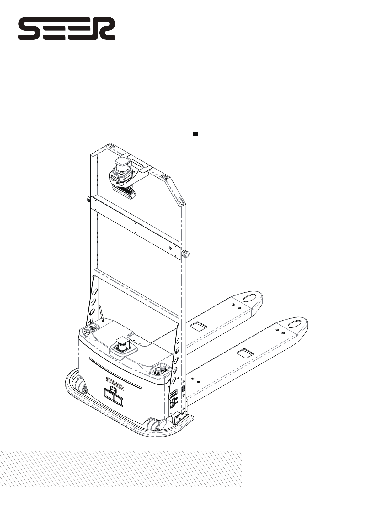
SMF-MP10S (Seer Mini Fork) is a laser SLAM mini automatic forklift. The product provides
core map building, positioning and navigation functions to help users quickly realize various
applications of mobile robots.
This product is developed and manufactured by Shanghai Seer Intelligent Technology
Corporation. All rights © are reserved by Shanghai Seer Intelligent Technology Corporation.
Although some names in this document and possible other names are not marked with the
registered trademark symbol®, but they are registered trademarks of Shanghai Seer
Intelligent Technology Corporation, including 仙工智能, SEER and SRC.
3.2 Product Dimensions
3.2.1 Dimensions of Robot

3. Product Introduction
SMF-MP10S User guide V1.1 Shanghai Seer Intelligent Technology Corporation 9
S/N Definition SMF-MP10S (mm)
L1 Body length (including bumper) 1585
b1 Total width of body 885
H1 Total height of body 1836
H3 Lifting height 174
H5 Fork height (lowest) 104
s/e/l Fork size 186×60×1154
b3 Outer width of fork 570
m Minimum ground clearance 40
L3 Distance from laser to drive wheel 856
L2 Distance from fork baffle to drive wheel 636
Ast 1000X1200Aisle width, 1000x1200mm pallet
crosswise (1200 along the fork edge) 1990
Wa Minimum radius of pivot steering 1035
H2 Height of laser scanning 1800
H4 Height of obstacle avoidance scanning 478
R1 Size of drive wheel 50
R2 Size of load wheel 40
b11 Track width (drive wheel) 400
b2 Track width (balancing wheel) 615
Y Wheelbase 842

3. Product Introduction
SMF-MP10S User guide V1.1 Shanghai Seer Intelligent Technology Corporation 10
3.2.2 Coordinate System of gyroscope
The data of gyroscope in the coordinate system of the robot can be used to detect slippage.
High style (New version)
S/N Definition SMF-MP10S
x Refers to the offset of the position where the controller is
installed in the x axis of the coordinate system 772.5mm
y Refers to the offset of the position where the controller is
installed in the y axis of the coordinate system 158.38mm
z Refers to the offset of the position where the controller is
installed in the z axis of the coordinate system 278mm
yaw Refers to the degree of yaw where the controller is installed
relative to the coordinate system of the cart -90°
qx Refers to the x component of the quaternion (reserved, no
need to be filled in) /
qy Refers to the y component of the quaternion (reserved, no
need to be filled in) /
qz Refers to the z component of the quaternion (reserved, no
need to be filled in) /
qw Refers to the w component of the quaternion (reserved, no
need to be filled in) /
faceUP Refers to the orientation of the controller 2

3. Product Introduction
SMF-MP10S User guide V1.1 Shanghai Seer Intelligent Technology Corporation 11
Short style (old version)
S/N Definition SMF-MP10S
x Refers to the offset of the position where the controller is
installed in the x axis of the coordinate system 780mm
y Refers to the offset of the position where the controller is
installed in the y axis of the coordinate system 158.38mm
z Refers to the offset of the position where the controller is
installed in the z axis of the coordinate system 180mm
yaw Refers to the degree of yaw where the controller is installed
relative to the coordinate system of the cart -90°
qx Refers to the x component of the quaternion (reserved, no
need to be filled in) /
qy Refers to the y component of the quaternion (reserved, no
need to be filled in) /
qz Refers to the z component of the quaternion (reserved, no
need to be filled in) /
qw Refers to the w component of the quaternion (reserved, no
need to be filled in) /
faceUP Refers to the orientation of the controller 2
3. Product Introduction
SMF-MP10S User guide V1.1 Shanghai Seer Intelligent Technology Corporation 12
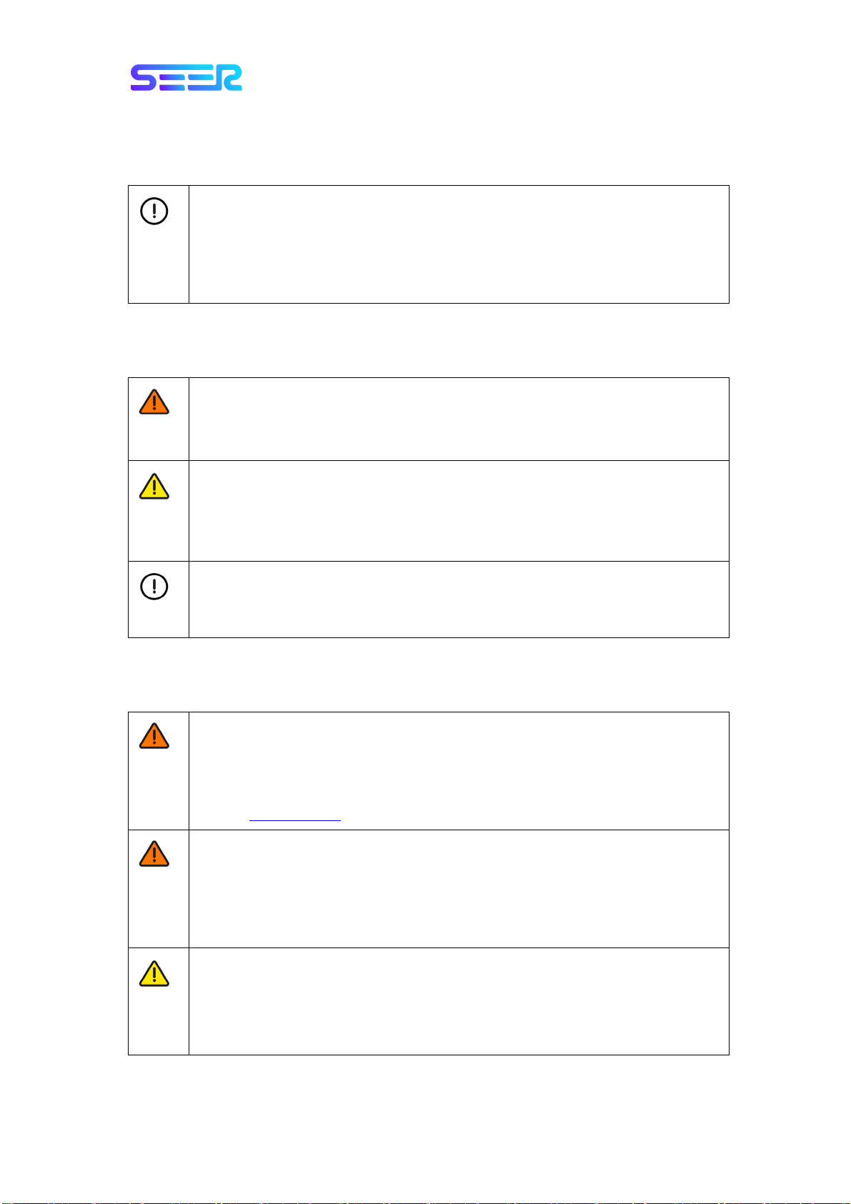
3.3 Main Labels
3.3.1 Precautions
3. Product Introduction
SMF-MP10S User guide V1.1 Shanghai Seer Intelligent Technology Corporation 13
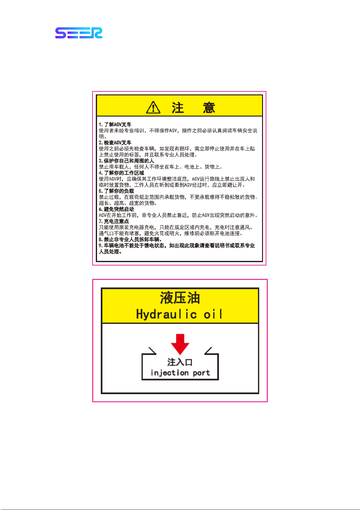
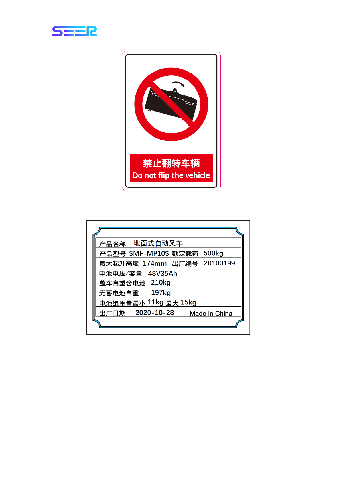
3.3.2 Nameplate
3. Product Introduction
SMF-MP10S User guide V1.1 Shanghai Seer Intelligent Technology Corporation 14
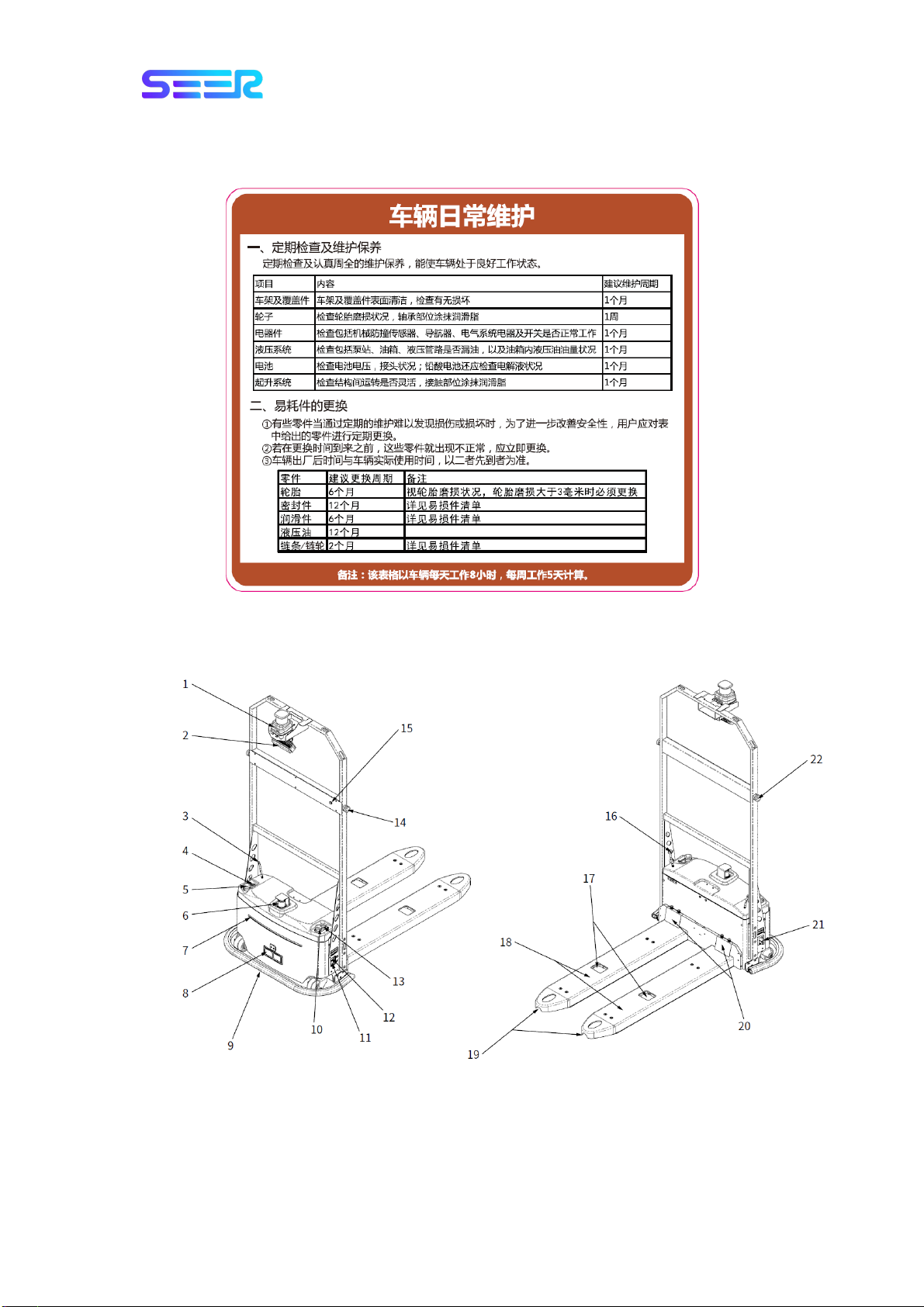
3.3.3 Daily Maintenance of Robot
3.4 Configuration of Body
Table of contents
Other SEER Forklift manuals

Popular Forklift manuals by other brands

Jungheinrich
Jungheinrich EJC 214 operating instructions

KAUP
KAUP T456BZ Series operating manual

Presto Lifts
Presto Lifts PPS2200-62NFO-21 Installation, operation and service manual

EP Equipment
EP Equipment EPL151 Operation manual

Still
Still FM-X-10 Original instructions

Hyundai
Hyundai 110DF-7 operating manual


