EKKO ES40E Operating manual

Electric Scissor Lift Work Platform
Operator’s and Service Manual
Applies to
ES40E/ES60E/ES80E/ES100E/ES120E
Frist Edition January 2022

Attention
You should read, understand and follow these
safety rules and operating instructions before
operating this machine. Only trained or allowed
by authorized person can operate the machine.
This manual should be remained with the
machine at all time and considered a
permanent part of your machine. If you have
any questions please contact us
OwnersUsers and Operators:
Thank you for choosing our company and use
our machines. Our number one priority is user
safety, which is best achieved by our joint
efforts. We think that as a user and operator, if
you can comply with the following requirements,
will be very helpful for safe use of the
equipment:
1.Comply with the user rules, workplace rules
and government rules.
2.Read, understand and comply with the
manual and other instructions in manuals.
3.Routinel perform good safety work practices.
4.Only trained/certified operator or under the
guidance of a supervisors who has the
certificate can run the machine.
If there are any ambiguous in the manual or
you think we should add some contents, please
contact.
Contents
SafetyRules.................................................................1
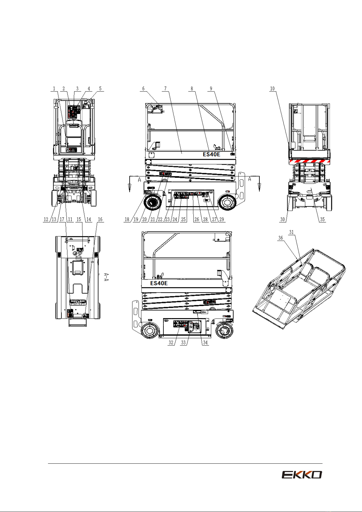
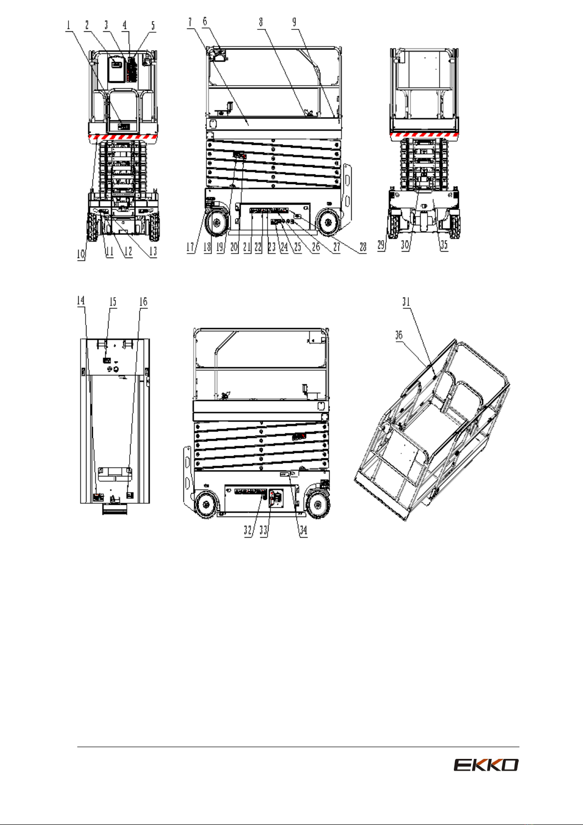
Decals............................................................................2
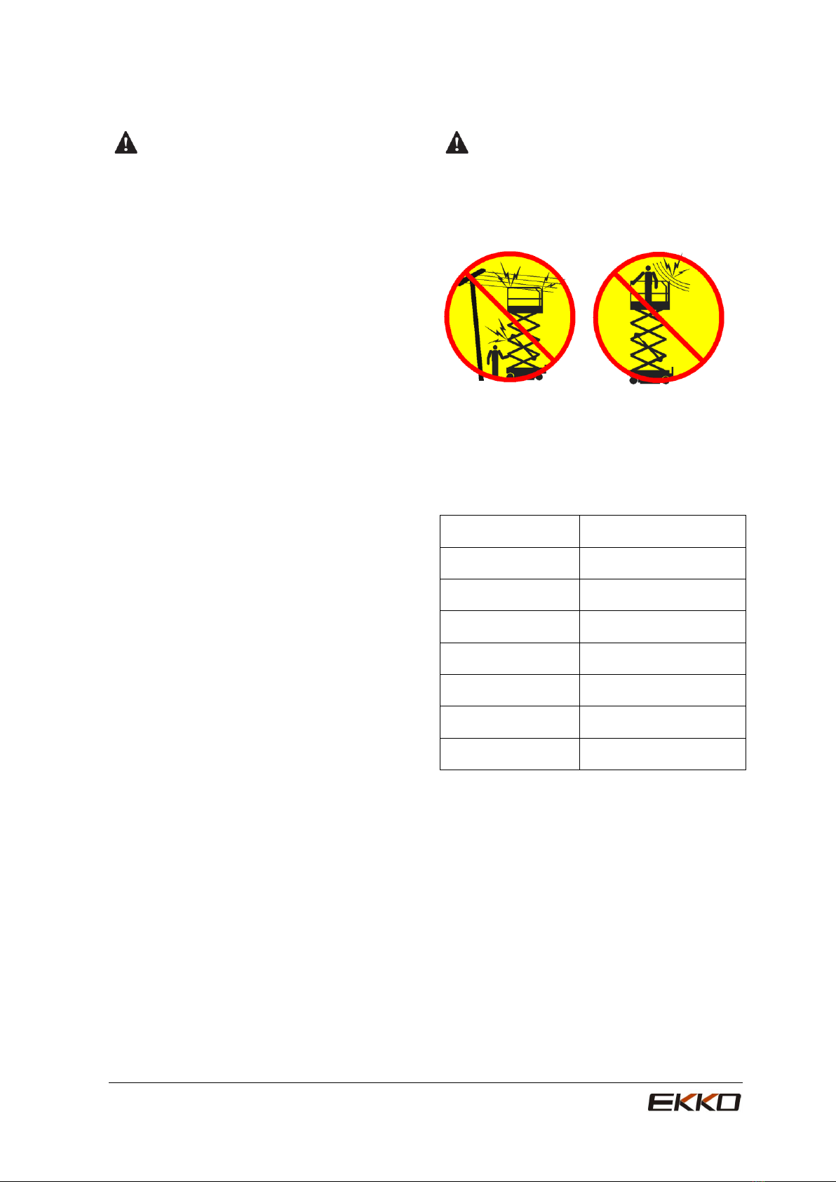
PersonalSafety............................................................6
WorkAreaSafety.........................................................7
Legend........................................................................12
Controls.......................................................................14
Pre-operationInspection...........................................17
FunctionTest..............................................................19
WorkplaceInspection................................................22
OperatingInstructions...............................................23
TransportingAndLiftingInstructions........................28
Specifications..............................................................31
Maintenance...............................................................35
ElectricalSchematicDiagram..................................52
HydraulicSchematicDiagram..................................53
MaintenanceRecord.................................................56

Safety Rules
1
Danger
Failure to obey the instructions
and safety rules in this manual
will result in death or serious
injury.
Do not operate, unless:
√You have learned and practiced the
principles of safe machine operation
contained in this operator’s manual.
1. Avoid hazardous situations.
Know and understand the safety rules
before going on the next section.
2 Always perform a pre-operation
inspection.
3 Always perform function tests prior to
use.
4 Inspect all the workplace.
5 Only use the machine as it was
intended.
√You should read, understand and obey the
manufacturer’s instructions and safety rules
—— safety manual, operator’s manual and
machine decals.
√You should read, understand and obey
employer’s safety rules and workplace rules.
√You should read, understand and obey all
applicable governmental regulations.
√You are properly trained to safely operate
the machine.
Hazard Classification
products use symbols, color coding and
signal words to identify the following:
Safety alert symbol—used to alert
you to potential personal injury hazards.
Obey all safety messages that follow this
symbol to avoid possible injury or death
Red Indicates a hazardous
situation which, if not avoided, will result in
death or serious injury.
Orange Indicates a hazardous
situation which, if not avoided, could result in
death or serious injury.
Yellow Indicates a hazardous
situation which, if not avoided, could result in
minor or moderate injury.
Blue Indicates a property
damage message.
Design intent
This machine is intended to be used only to
lift personnel, along with their tools and
materials to an aerial work site.
Safety Sign Maintenance
Replace any missing or damaged safety
signs. Keep operator safety in mind at all
times.
Use mild soap and water to clean safety
signs.
Do not use solvent-based cleaners because
they may damage the safety sign mater

Decals
2
Safety Decals and Location
Decals inspection of Model ES40E
Ensure that there are decals with words or
symbols on the machine. Using appropriate test
methods to check that if all labels are easy to
recognize and have a appropriate location.
There is a list containing number and description
No
.
Drawing
number
Description
Tot
al
1
A11000035
Maximum Capacity
1
2
A11000001
File Box
1
3
A11000002
Brief Instructions
1
4
A11000038
Manual Force, Only
Indoor 400N
1
5
A11000003
Tip-over Hazard
2
6
A11000004
Refer to Operator’s
Manual
1
7
A11000159
platform LOGO
2
8
A11000036
Model
2
9
A11000010
CE
1
10
A11000078
Warning Reflective Band
2
11
A11000020
Transport Tie-down
4
12
A11000021
Lifting Point
4
13
A11000032
Forklift Pocket
2
14
A11000029
Safety Arm
1
15
A11000031
Tip-over Hazard,Tilting
Switch
1
16
A11000028
Brake Release Safety
and Operating
Instructions
1
17
A11000012
Data Plate
1
18
A11000017
Directional Arrows
2
19
A11000039
Wheel Load
4
20
A11000015
Crushing Hazard
2
21
A11000016
Crushing Hazard
2
22
A11000025
Electrocution Hazard
2
23
A11000027
Tip-over Hazard, Open
Trays
2
24
A11000076
Tip-over Hazard,
Batteries
1
25
A11000024
Use Safety Arm
2
26
A11000026
Batteries/Charger Safety
1
27
A11000018
Power to Charger
1
28
A11000030
Electrocution Hazard,
Plug
1
29
A11000011
Power to Platform,230V
2
30
A11000033
Transport Diagram
2
31
A11000005
Lanyard Anchorage
Point
4
32
A11000023
Compartment Access
1
33
A11000019
Ground Control Panel
1
34
A11000022
Emergency Lowering
1
35
A11000159
Chassis logo
1
36
A11000156
Non-Insulated
4

Decals
3

Decals
4
Safety Decals and Location
Decals inspection of Model
ES60E
Ensure that there are decals with words or
symbols on the machine. Using appropriate test
methods to check that if all labels are easy to
recognize and have a appropriate location.
There is a list containing number and description:
No
.
Drawing
number
Description
Tot
al
1
A11000062
Maximum Capacity,
ES0607W
1
2
A11000140
File Box
1
3
A11000141
Brief Instructions
1
4
A11000143
Manual Force, Indoor
400N, Outdoor 200N
(ES60)
1
5
A11000003
Tip-over Hazard
2
6
A11000142
Refer to Operator’s
Manual
1
7
A11000133
platform LOGO
2
8
A11000053
Model,ES0607W
2
9
A11000010
CE
1
10
A11000078
Warning Reflective
Band,ES07
2
11
A11000020
Transport Tie-down
4
12
A11000021
Lifting Point
4
13
A11000032
Forklift Pocket
2
14
A11000029
Safety Arm
1
15
A11000031
Tip-over Hazard,Tilting
Switch
1
16
A11000028
Brake Release Safety
and Operating
Instructions
1
17
A11000012
Data Plate
1
18
A11000017
Directional Arrows
2
19
A11000151
Wheel Load,ES0607W
4
20
A11000145
Crushing Hazard
2
21
A11000146
Crushing Hazard
2
22
A11000025
Electrocution Hazard
2
23
A11000027
Tip-over Hazard, Open
Trays
2
24
A11000076
Tip-over Hazard,
Batteries, ES07
1
25
A11000024
Use Safety Arm
2
26
A11000026
Batteries/Charger Safety
1
27
A11000018
Power to Charger
1
28
A11000030
Electrocution Hazard,
Plug
1
29
A11000011
Power to Platform,230V
2
30
A11000033
Transport Diagram
2
31
A11000005
Lanyard Anchorage
Point
4
32
A11000023
Compartment Access
1
33
A11000019
Ground Control Panel
1
34
A11000022
Emergency Lowering
1
35
A11000134
Chassis logo,
1
36
A11000156
Non-Insulated
4

Decals
5

Decals
6
Safety Decals and Location
Decals inspection of Model
ES80E/ES100E/ES120E
Ensure that there are decals with words or
symbols on the machine. Using appropriate test
methods to check that if all labels are easy to
recognize and have a appropriate location.
There is a list containing number and description:
No
.
Drawing
number
Description
Tot
al
1
A11000058
Maximum Capacity,
ES80E
1
A11000006
Maximum Capacity,
ES100E
1
A11000042
Maximum Capacity,
ES120E
1
2
A11000140
File Box
1
3
A11000141
Brief Instructions
1
4
A11000143
Manual Force, Indoor
400N, Outdoor 200N
(ES80E/ES100E)
1
A11000144
Manual Force, Only
Indoor400N(ES120E)
1
5
A11000003
Tip-over Hazard
2
6
A11000142
Refer to Operator’s
Manual
1
7
A11000090
Platform logo
2
8
A11000047
Model,ES80E
2
A11000008
Model,ES100E
2
A11000048
Model,ES120E
2
9
A11000010
CE
1
10
A11000009
Warning Reflective
Band,
2
11
A11000020
Transport Tie-down
4
12
A11000021
Lifting Point
4
13
A11000032
Forklift Pocket
2
14
A11000012
Data Plate
1
15
A11000031
Tip-over Hazard,Tilting
Switch
1
16
A11000028
Brake Release Safety
and Operating
Instructions
1
17
A11000017
Directional Arrows
2
18
A11000152
Wheel Load,ES80E
4
A11000148
Wheel Load,ES100E
4
A11000149
Wheel Load,ES120E
4
19
A11000145
Crushing Hazard
2
20
A11000146
Crushing Hazard
2
21
A11000027
Tip-over Hazard, Open
Trays
2
22
A11000024
Use Safety Arm
2
23
A11000025
Electrocution Hazard
2
24
A11000030
Electrocution Hazard,
Plug
1
25
A11000018
Power to Charger
1
26
A11000034
Tip-over Hazard,
Batteries
(ES80E/ES100E)
1
A11000044
Tip-over Hazard
Batteries,(ES120E)
1
27
A11000011
Power to Platform,230V
2
28
A11000026
Batteries/Charger Safety
1
29
A11000033
Transport Diagram
2
30
A11000029
Safety Arm
1
31
A11000005
Lanyard Anchorage Point
4
32
A11000023
Compartment Access
1
33
A11000019
Ground Control Panel
1
34
A11000022
Emergency Lowering
1
35
A11000007
Chassis logo,
1
36
A11000156
Non-Insulated
4

Decals
7

Personal Safety Work Area Safety
8
Personal Fall Protection
Personal fall protection equipment (PFPE) is
not required when operating this machine. If
PFPE is required by job site or employer
rules, the following shall apply:
All PFPE must comply with applicable
governmental regulations and must be
inspected and used in accordance with the
manufacturer’s instructions.
Electrocution Hazards
This machine is not electrically insulated and
will not provide protection from contact with or
proximity to electrical current.
Obey all local and governmental regulations
regarding required clearance from electrical
power lines. At a minimum, the required
clearance contained in the chart below must
be followed.
Line Voltage
Required Clearance
0 to 300V
Don’t touch
300V to 50KV
120 Inch
50KV to 200KV
181 Inch
200KV to 350KV
240 Inch
350KV to 500KV
300 Inch
500KV to 750KV
420 Inch
750KV to 1000KV
540 Inch
Allow for platform movement, electrical line
sway or sag, and beware of strong or gusty
winds.
Keep away from the machine if it contacts
energized power lines. Personnel on the
ground or in the platform must not touch or
operate the machine until energized power
lines are shut off.
Do not operate the machine during lightning or
storms.
Do not use the machine as a ground for
welding

Work Area Safety
9
Tip-over Hazards
Occupants, equipment and materials shall not
exceed the maximum platform capacity or the
maximum platform capacity of the platform
extension.
Model
Platform
retracted
Extension
only
Maximum
occupants
ES40E
500 lbs
220 lbs
Indoor-2P
ES60E
500 lbs
260 lbs
Indoor-2P
Outdoor-2P
ES80E
990 lbs
260 lbs
Indoor-2P
Outdoor-1P
ES100E
700 lbs
260 lbs
Indoor-2P
Outdoor-1P
ES120E
700 lbs
260 lbs
Only
indoor-2P
Maximum occupants Platform retracted
Platform only
Do not raise the platform unless the machine
is on a firm, level surface.
Do not drive over 0.8 km/h with the platform
raised.
Do not depend on the tilt alarm as a level
indicator. The tilt alarm sounds on the chassis
only when the machine is on a severe slope.
If the tilt alarm sounds:
Lower the platform. Move the machine to a
firm, level surface. If the tilt alarm sounds
when the platform is raised, use extreme
caution to lower the platform.
Outdoor Use: Do not raise the platform when
wind speeds may exceed 12.5 m/s. If wind
speeds exceed 12.5 m/s when the platform is
raised, lower the platform and do not continue
to operate the machine.
Indoor Use: When raising the platform, follow
ratings for allowable side force and number of
occupants on the right.
Do not operate the machine in strong or gusty
winds. Do not increase the surface area of the
platform or the load. Increasing the area
exposed to the wind will decrease machine
stability.
Do not drive the machine on or near uneven
terrain, unstable surfaces or other hazardous
conditions with the platform raised.

Work Area Safety
10
Do not use controller to release the platform
when the platform is stripped, stuck or
impeded its normal movement by nearby
objects. Everyone must leave away from the
platform before intending to release platform
by ground controller.
Use extreme care and slow speeds while
driving the machine in the stowed position
across uneven terrain, debris, unstable or
slippery surfaces and near holes and drop-offs
with the platform stated.
Do not use the machine as a crane.
Do not push the machine or other objects with
the platform.
Do not contact adjacent structures with the
platform.
Do not tie the platform to adjacent structures.
Do not place loads outside the platform
perimeter.
Do not push off or pull toward any object
outside of the platform.
Maximum allowable manual force
Model
Platform
retracted
Extension only
ES40E
400N
Only indoor-2P
ES60E
400N
Indoor-2P
200N
Outdoor-2P
ES80E
400N
Indoor-2P
200N
Outdoor-2P
ES100E
400N
Indoor-2P
200N
Outdoor-1P
ES120E
400N
Indoor-2P
Do not alter or disable the limit switches.
Do not alter or disable machine components
that in any way affect safety and stability.
Do not replace items critical to machine
stability with items of different weight or
specification.
Do not modify or alter an aerial work platform
without prior written permission from the
manufacturer. Install additional devices for
placing tools or other materials on to the
platform, skirting boards and rails, it will
increase the weight of platform and increase
loading of the platform surface.
Do not place or attach fixed or overhanging
loads to any part of this machine.
Do not place ladders or scaffolds in the
platform or against any part of this machine.
Do not transport tools and materials unless
they are evenly distributed and can be safely
handled by person(s) in the platform.
Do not use the machine on a moving or mobile
surface or vehicle.
Be sure all tires are in good condition, castle
nuts are properly tightened and cotter pins are
properly installed.

Work Area Safety
11
Crushing Hazard
Keep hands and limbs out of scissors.
Do not work under the platform or in the
scissor links without the safety arm in place.
Use common sense and planning when
operating the machine with the controller from
the ground. Maintain safe distances between
the operator, the machine and fixed objects.
Keep safety away from the operator, machine
and fixed object.
Operation on Slopes Hazards
Do not drive the machine on a slope that
exceeds the slope and side slope rating of the
machine. Slope rating applies to machines in
the stowed position.
Model
Maximum
slope
rating,
stowed
position
Maximum
side slope
rating,
stowed
position
ES40E
25%(14°)
25%(14°)
ES60E
25%(14°)
25%(14°)
ES80E
30% (17°)
30%(17°)
ES100E
25% (14°)
25% (14°)
ES120E
25% (14°)
25% (14°)
Note: Slope rating is subject to ground
conditions and adequate traction.
Fall Hazards
The guard rail system provides fall protection.
If occupant(s) of the platform are required to
wear personal fall protection equipment
(PFPE) due to job site or employer rules,
PFPE and its use shall be in accordance with
the PFPE manufacturer’s instructions and
applicable governmental requirements.
Do not sit, stand or climb on the platform
guard rails. Maintain a firm footing on the
platform floor at all times.
Do not climb down from the platform when
raised.
Keep the platform floor clear of debris.
Do not enter or exit the platform unless the
machine is in the stowed position.
Do not operate the machine unless the guard
rails are properly installed and the entry is
secured for operation.
Collision Hazards
Be aware of limited sight distance and blind
spots when driving or operating.
Be aware of extended platform position when
moving the machine.
Operators must comply with employer, job site
and governmental rules regarding use of
personal protective equipment.
Check the work area for overhead
obstructions or other possible hazards.

Work Area Safety
12
Be aware of crushing hazards when grasping
the platform guard rail.
Observe and use color-coded direction arrows
on the platform controls and the platform decal
plate for drive and steer functions.
Do not operate a machine in the path of any
crane or moving overhead machinery unless
the controls of the crane have been locked out
and/or precautions have been taken to
prevent any potential collision.
No stunt driving or horseplay while operating a
machine.
Do not lower the platform unless the area
below is clear of personnel and obstructions.
Limit travel speed according to the condition
of the ground surface, congestion, slope,
location of personnel, and any other factors
which may cause collision.
Component Damage
Hazards
Do not use any battery charger greater than
24V to charge the batteries.
Do not use the machine as a ground for
welding.
Explosion and Fire Hazards
Only in the open, ventilated and away from fire
place such as sparks, flame and burned
cigarettes, can charge for battery.
Do not operate the machine in hazardous
locations or locations where potentially
flammable or explosive gases or particles may
be present.
Damaged Machine Hazards
Do not use a damaged or malfunctioning
machine. Conduct a thorough pre-operation
inspection of the machine and test all
functions before each work shift. Immediately
tag and remove from service a damaged or
malfunctioning machine.
Be sure all maintenance has been performed
as specified in this manual and the
appropriate service manual.
Be sure all decals are in place and legible.
Be sure the operator's, safety and
responsibilities manuals are complete, legible
and in the storage container located on the
machine.
Bodily Injury Hazard
Do not operate the machine with a hydraulic
oil or air leak. An air leak or hydraulic leak can
penetrate and/or burn skin.
Improper contact with components under any
cover will cause serious injury. Only trained
maintenance personnel should access
compartments. Access by the operator is only
advised when performing a pre-operation
inspection. All compartments must remain
closed and secured during operation.
Battery Safety
Burn Hazards
Batteries contain acid. Always wear protective
clothing and eye wear when working with
batteries.
Avoid spilling or contacting battery acid.
Neutralize battery acid spills with baking soda
and water.
Do not expose the batteries or the charger to
water or rain during charging.

Work Area Safety
13
Explosion Hazard
Keep sparks, flames and
lighted tobacco away
from batteries. Batteries
emit explosive gas.
The battery tray should
remain open during the
entire charging cycle.
Do not contact the
battery terminals or the
cable clamps with tools
that may cause sparks.
Component Damage Hazard
Do not use any battery charger greater than
24V to charge the batteries.
When the battery power is insufficient or
excessive discharge, do not operate the
machine.
Electrocution/Burn Hazards
Connect the battery charger to a grounded,
AC 3-wire electrical outlet only.
Inspect daily for damaged cords, cables and
wires. Replace damaged items before
operating.
Avoid electrical shock from contact with
battery terminals. Remove all rings, watches
and other jewelry.
Tip-over Hazards
Batteries are used as counterweight and are
critical to machine stability. Do not use
batteries that weigh less than the original
equipment. Each battery must weigh 61.5lbs
(ES120 battery is 80 lbs), Battery tray
including batteries must weigh a minimum of
the following requirements:
Model
Weight of tray
ES40E
170 lbs
ES60
340 lbs
ES80
ES100
400 lbs
ES120
465 lbs
Lift Hazard
Use the appropriate number of people and
proper lifting techniques when lifting batteries.
Lockout after each use
1. Select a safe parking location—firm level
surface, clear of obstruction and traffic.
2. Lower the platform.
3. Turn the key switch to the off position and
remove the key to secure from
unauthorized use.
4. Chock the wheels.
5. Charge the batteries.

Legend
14
ES40E
123
4
5
6
7
8
9
10
11
12
13
14
15
16
17
18
19
20
1 Platform guard rails
2 Lanyard anchorage points
3 Manual storage container
4 Platform controls
5 Platform extension
6 Platform-socket and air pipes(optional)
7 Scissor arm
8 Transport tie-down
9 Steering wheel
10 Pothole guard
11 Ground controls
12 Timer
13 Non-steering wheel
14 Brake release pump
15 Entry ladder
16 Emergency lowering line
17 Lift cylinder
18 Safety arm
19 Platform entry chain or gate
20 Platform extension release pedal

Legend
15
ES60E
1 Platform guard rails
2 Lanyard anchorage points
3 Manual storage container
4 Platform controls
5 Platform extension
6 Platform-socket and air pipes(optional)
7 Scissor arm
8 Transport tie-down
9 Steering wheel
10 Pothole guard
11 Ground controls
12 Timer
13 Non-steering wheel
14 Brake release pump
15 Entry ladder
16 Emergency lowering line
17 Lift cylinder
18 Safety arm
19 Platform entry chain or gate
20 Platform extension release pedal
123
4
5
6
7
8
9
10
11
12
13
14
15
16
17
18
19
20

Legend
16
ES80E/ES100E/ES120E
12
34
5
6
7
8
9
10
11
12
13
14
15
16
17
18
19
20
1 Platform guard rails
2 Lanyard anchorage points
3 Manual storage container
4 Platform controls
5 Platform extension
6 Platform-socket and air pipes(optional)
7 Scissor arm
8 Transport tie-down
9 Steering wheel
10 Pothole guard
11 Timer
12 Ground controls
13 Non-steering wheel
14 Brake release pump
15 Entry ladder
16 Emergency lowering line
17 Lift cylinder
18 Safety arm
19 Platform entry chain or gate
20 Platform extension release pedal

Controls
17
A11000019A11000019
G
R
M
E
E
Y
C
N
E
O
P
T
S
1
2
3
4
5
6
7
8
9
10
Ground Control Panel
1 Key switch for platform/off/ground selection
10 Lifting key
Turn the key switch to the platform position and
the platform controls will operate. Turn the key
switch to the off position and the machine will be
off. Turn the key switch to the ground position
and the ground controls will operate.
Press and hold the lifting key and the platform
rising key at the same time can operate the
ascending function.
Press and hold the lifting key and the platform
2 Red Emergency Stop button
lowering key at the same time can operate the
ascending function.
Push in the red Emergency Stop button to the off
position to stop all functions. Pull out the red
Emergency Stop button to the on position to
operate the machine.
3 A breaker for electrical circuits
4 Return key
5 Page up key
6 Page down key
7 Enter key
8 Platform rise key
9 Platform down key
Platform lowering function.

Controls
18
Platform Control panel
Platform control panel
1 Thumb rocker switch for steer function
5 Horn button
2Drive function button
6 Lift function button
3 Drive speed select button
7LED
4 Red Emergency Stop button
8 Proportional control handle and function
enable switch for drive and lift functions
This manual suits for next models
4
Table of contents
Other EKKO Forklift manuals