SEF 551.10 User manual
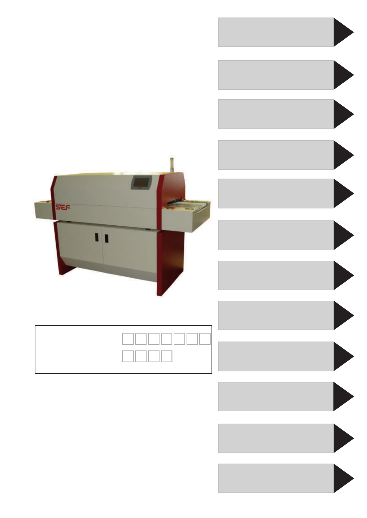
Serial number:
Year of manufac-
turing:
Keep this manual for a later use.
2
1
3
4
5
6
7
8
9
10
11
12
Schematic diagram
Options and
spare parts
Notes
© SEF Systec GmbH, December 2015
Translation of original instruction.
Subject to technical changes.
Operating Manual
System settings
Operation and
start-up
Transport and
installation
Technical data
Safety instructions
Preface
Warranty
Prole administration
Maintenance and
service
p551.10 4heating zones
p551.15 5heating zones
p551.19 8heating zones


Table of content
Table of content 551.19 \ 12.2015 \
Page 0.3
2.0 Safety instructions
Safety signs............................................................................................... 2.2
General instructions................................................................................... 2.3
Safety notes............................................................................................... 2.3
Used norms ............................................................................................... 2.4
Intended use.............................................................................................. 2.5
Remaining risks ..................................................................................... 2.5
Responsibility of operator and operating staff ........................................... 2.6
Owner ................................................................................................... 2.6
Operator................................................................................................ 2.6
Skilled and qualied operating staff ...................................................... 2.6
Authorised service staff......................................................................... 2.6
Responsibility of operator and operating staff ........................................... 2.7
Legal safety requirements .................................................................... 2.7
Personal safety ..................................................................................... 2.7
Reference to other suppliers................................................................. 2.7
Spare parts ........................................................................................... 2.7
Safety notes for installation and initial start-up.......................................... 2.9
Connection conditions .......................................................................... 2.9
Location ................................................................................................ 2.9
Exhaustion ............................................................................................ 2.9
Safety notes for daily start of operation and automatic operation ........... 2.11
Safety at the working place................................................................. 2.11
Solder paste and chip adhesive.......................................................... 2.11
Protective equipment .......................................................................... 2.11
Failures ............................................................................................... 2.13
Optical signals .................................................................................... 2.13
Safety notes for maintenance and service .............................................. 2.14
Five safety rules.................................................................................. 2.14
Dismounting of safety devices ............................................................ 2.15
Disposal notes .................................................................................... 2.16
1.0 Preface
Preface ....................................................................................................... 1.1
3.0 Warranty
Warranty ................................................................................................... 3.2
Rights of use.......................................................................................... 3.2
Assignment of the rights of use ............................................................. 3.2
Liability................................................................................................... 3.2
Reshipment ........................................................................................... 3.2
Modications or improvements of the product....................................... 3.3
Special restrictions ................................................................................ 3.3
Caveat emptor.......................................................................................... 3.3

Table of content
Table of content 551.19 \ 12.2015 \
Page 0.4
4.0 Technical data
Dimensions of the soldering system 551.10 / 551.15................................ 4.2
Technical data 551.10 / 551.15.................................................................. 4.3
Dimensions............................................................................................. 4.3
Electrical connection values ................................................................... 4.3
Allowed climatic demands ...................................................................... 4.3
Allowed component sizes ....................................................................... 4.3
Characteristics........................................................................................ 4.3
Emissions ............................................................................................... 4.3
Dimensions of the soldering system 551.10 / 551.15
with power supply 220V triangle circuit .................................................. 4.4
Technical data
Option power supply 220V in triangle circuit .......................................... 4.5
Dimensions............................................................................................. 4.5
Electrical connection values ................................................................... 4.5
Maße des Lötsystems 551.19 ................................................................... 4.6
Technical data 551.19................................................................................ 4.7
Dimensions............................................................................................. 4.7
Electrical connection values ................................................................... 4.7
Allowed climatic demands ...................................................................... 4.7
Allowed component sizes ....................................................................... 4.7
Characteristics........................................................................................ 4.7
Emissions ............................................................................................... 4.7
Functional scheme 551.10 - 4 heating zones ........................................... 4.8
Funktional scheme 551.15 - 5 heating zones ........................................... 4.8
Funktional scheme 551.19 - 8 heating zones ........................................... 4.8
Functional scheme ................................................................................... 4.9
Heating chamber .................................................................................... 4.9
Cooling zone, Exhaust hood................................................................... 4.9
Transport ................................................................................................ 4.9
Operating panel 7‘‘ touch screen ............................................................ 4.11
Controller (SBCC-Board)......................................................................... 4.13
Central electrics 551.10 / 551.15............................................................. 4.14
Central electrics 551.19........................................................................... 4.14
Central electrics....................................................................................... 4.15
Controller RO-R2R .................................................................................. 4.17
Allocation of the signals for 551.19.......................................................... 4.18
Controller 551.19 Master / Slave............................................................. 4.19
Option pin chain conveyor for 551.10/.15 ............................................. 4.19
Component sizes pin chain conveyor................................................. 4.19
Parameters pin chain conveyor.......................................................... 4.19
Base cabinet 551.10.1............................................................................. 4.21
Option exhaust box 551.10.2 ............................................................... 4.23

Table of content
Table of content 551.19 \ 12.2015 \
Page 0.5
5.0 Transport and setting up
Transport notes ......................................................................................... 5.2
Safety instructions for mounting and dismounting..................................... 5.3
Liability.................................................................................................... 5.3
Unpacking.................................................................................................. 5.5
Checking scope of delivery..................................................................... 5.5
Transport on pallet.................................................................................. 5.5
Dimensions and data of the soldering system 551.10 / 551.15................. 5.6
System 551.10 / 551.15 setup and alignment ........................................... 5.7
Working table.......................................................................................... 5.7
Dimensions and data of the soldering system 551.19............................... 5.8
System 551.19 setup and alignment ......................................................... 5.9
Align soldering system horizontally....................................................... 5.10
Mains supply......................................................................................... 5.10
Name plate 400VAC/N/PE.................................................................... 5.10
Power supply 400VAC/N/PE ................................................................ 5.10
Name plate 220VAC D...................................................................... 5.11
Power supply 220VAC D.................................................................. 5.11
Exhaust connection .............................................................................. 5.13
Interfaces.............................................................................................. 5.14
Main switch........................................................................................... 5.14
Operating switch On/Off ....................................................................... 5.14
Operation by touch panel ..................................................................... 5.14
Prole setting........................................................................................ 5.14
Integrated temperature proler............................................................. 5.14
Final check .............................................................................................. 5.15
Dismounting, storage and preservation................................................... 5.16
Dismounting.......................................................................................... 5.16
Short-term out-of-operation .................................................................. 5.16
Preservation ......................................................................................... 5.16
6.0 Function and start-up
Functional description................................................................................ 6.3
Heating chamber .................................................................................. 6.3
Thermocouples ..................................................................................... 6.3
Cooling zone......................................................................................... 6.3
Exhaustion ............................................................................................ 6.3
Mesh belt .............................................................................................. 6.5
Operating the system............................................................................ 6.5
Machine status...................................................................................... 6.5
Temperature proler.............................................................................. 6.7
Emergency-stop.................................................................................... 6.7
Safety circuit ......................................................................................... 6.7
The operating panel................................................................................... 6.9
Touch screen controller based on SBCC.............................................. 6.9

Table of content
Table of content 551.19 \ 12.2015 \
Page 0.6
7.0 Prole administration
Parameter adjustment ............................................................................... 7.3
Parameters for temperature prole....................................................... 7.3
Preheating time..................................................................................... 7.3
Critical prole parameters
Time above liquidus .............................................................................. 7.5
Cooling time.......................................................................................... 7.5
Critical prole parameters
Example component thickness 1,6 mm - 2,5 mm(small components) . 7.6
Critical prole parameters
Example component thickness > 2,5 mm (small components)............. 7.6
Peaktemperature .................................................................................. 7.7
Ramp-up / Ramp-down gradient........................................................... 7.7
Load program .......................................................................................... 7.10
Select program ................................................................................... 7.11
Load program .................................................................................... 7.11
Edit program............................................................................................ 7.13
Create soldering or curing prole........................................................ 7.13
Adjust nominal temperature................................................................ 7.13
Adjust conveyor speed ....................................................................... 7.15
Save program.......................................................................................... 7.17
Overwrite program .............................................................................. 7.18
Turn the soldering system on/off ............................................................ 6.11
Main switch ......................................................................................... 6.11
Turn soldering system on.................................................................... 6.11
The system screen .................................................................................. 6.11
Basic structure of screen .................................................................... 6.12
System display.................................................................................... 6.13
Operating modes of soldering systems series 551............................. 6.13
Menu structure Load program ................................................................. 6.14
Load program .......................................................................................... 6.15
Select program ................................................................................... 6.15
Load program .................................................................................... 6.15
Menu structure Edit program................................................................... 6.16
Edit program............................................................................................ 6.17
Create soldering or curing prole........................................................ 6.17
Menu structure Save program................................................................. 6.18
Save program.......................................................................................... 6.19
Save program.......................................................................................... 6.19
Prole measurement ............................................................................... 6.23
Temperature proler............................................................................ 6.23
Menu structure Prole measurement ...................................................... 6.24
Menu structure Setup .............................................................................. 6.26
Setup ....................................................................................................... 6.27

Table of content
Table of content 551.19 \ 12.2015 \
Page 0.7
8.0 System settings
Language selection ................................................................................... 8.3
Set language......................................................................................... 8.3
Colour scheme .......................................................................................... 8.5
Select colour scheme ........................................................................... 8.5
Temperature display .................................................................................. 8.7
Select temperature display ................................................................... 8.7
Activate password protection for programs ............................................... 8.9
Activate password protection................................................................ 8.8
Standby parameters ................................................................................ 8.11
“Power Save Package” ....................................................................... 8.11
Set standby time ................................................................................. 8.11
Set standby temperature .................................................................... 8.11
Software-Update...................................................................................... 8.13
Install update ...................................................................................... 8.13
9.0 Maintenance and service
General safety instructions........................................................................ 9.2
Safety instructions for opening and closing the hood................................ 9.3
Set system out of operation....................................................................... 9.3
Opening the hood ................................................................................. 9.4
Closing the hood................................................................................... 9.5
Cleaning and maintenance intervals ......................................................... 9.6
Cleaning .................................................................................................... 9.6
Maintenance.............................................................................................. 9.6
Save program ..................................................................................... 7.19
Option pin chain conveyor ................................................................... 7.21
Adjust working width of pin chain conveyor ........................................ 7.21
Start production ....................................................................................... 7.22
Start system........................................................................................ 7.22
Heat-up phase .................................................................................... 7.22
Fill the oven ........................................................................................ 7.24
Start soldering or curing process ........................................................ 7.24
Cooling down phase 551.10 ............................................................... 7.25
Cooling down phase 551.19 ............................................................... 7.25
Cooling down phase 551.15 ............................................................... 7.25
Finish process..................................................................................... 7.25
Prole measurement ............................................................................... 7.27
Temperature proler ................................................................................ 7.27
Start measurement ............................................................................. 7.27
Stop measurement ............................................................................. 7.28
Stop or change production ...................................................................... 7.29
Change production ............................................................................. 7.29
Stop production................................................................................... 7.29
Switch system off..................................................................................... 7.30

Table of content
Table of content 551.19 \ 12.2015 \
Page 0.8
Lubrication................................................................................................. 9.7
Cleaning work............................................................................................ 9.9
Cleaning work at the outer machine body ............................................ 9.9
Cleaning of the reected-light barrier.................................................... 9.9
Cleaning of the blowers ..................................................................... 9.11
Cleaning of the fans............................................................................ 9.13
Cleaning of the exhaust hood “inlet” ................................................... 9.15
Cleaning of heating module ................................................................ 9.16
Cleaning of cooling module ................................................................ 9.16
Cleaning of the exhaust hood “outlet”................................................. 9.17
Cleaning of the guiding rails ............................................................... 9.19
Cleaning of the chamber oor............................................................. 9.19
Cleaning of the mesh belt ................................................................... 9.19
Error diagnosis ........................................................................................ 9.20
Check and exchange fuses ..................................................................... 9.23
Check and exchange fuses 551.10 / .15 ............................................ 9.23
Exchange damaged fuse ............................................................... 9.23
Check and exchange fuses 551.19 .................................................... 9.25
Exchange damaged fuse ............................................................... 9.25
Option power supply 220V in triangle circuit ................................... 9.26
Mounting plate inlet ................................................................... 9.27
Mounting plate outlet ................................................................. 9.27
Exchange blower..................................................................................... 9.29
Dismount blower ................................................................................. 9.29
Exchange fan........................................................................................... 9.31
Dismount fan....................................................................................... 9.31
Exchange heating elements of the upper heating modules .................... 9.33
Dismount heating module ................................................................... 9.33
Exchange upper heating element ....................................................... 9.36
Mount upper heating module .............................................................. 9.37
Exchange heating elements of lower heating zones ............................... 9.38
Dismount lower heating element ........................................................ 9.39
Exchange lower temperature sensor .................................................. 9.40
Mount lower heating element.............................................................. 9.40
Exchange temperature sensors in the upper heating modules ............... 9.43
Dismount upper heating module......................................................... 9.44
Exchange upper temperature sensor ................................................. 9.46
Mount upper heating module .............................................................. 9.46
Exchange temperature sensor in lower heating zone ............................. 9.49
Exchange lower temperature sensor .................................................. 9.50
Dismount operating panel........................................................................ 9.52
Exchange operating panel .................................................................. 9.53
Mount operating panel ........................................................................ 9.53
Dismount controller RO-R2R .................................................................. 9.54
Exchange controller board RO-R2R ................................................... 9.55

Table of content
Table of content 551.19 \ 12.2015 \
Page 0.9
10.0 Schematic diagram
12.0 Notes
11.0 Options and spare parts
Hardware for the network connection...................................................... 11.2
Option Communication Package ......................................................... 11.3
Network structure of SEF soldering system 551.xx.............................. 11.4
Default settings network conguration.................................................. 11.7
Network setup....................................................................................... 11.8
Network conguration........................................................................... 11.8
Windows control panel - network.......................................................... 11.8
Soldering system software RO-R2 - settings........................................ 11.8
Option Communication Package - network setup................................ 11.9
Create directories ............................................................................... 11.10
Server computer - directories ............................................................. 11.10
Soldering system software RO-R2 - settings...................................... 11.10
Server software setup......................................................................... 11.12
Port setup ........................................................................................... 11.13
Set admin interface ............................................................................ 11.13
Create user......................................................................................... 11.14
Assign directory .................................................................................. 11.15
Set up external operation ................................................................... 11.18
Option Communication Package - external operation ....................... 11.19
Congure VNC ................................................................................... 11.19
Option lamp pole for soldering systems 551.10/15/20....................... 11.21
Operating mode of the soldering system series 551 .......................... 11.21
MESY 570.77 A Temperature proler ................................................... 11.23
MESY 570.77 Insulating box ................................................................ 11.23
MESY 570.80 A Proler set .................................................................. 11.23
Thermocouples...................................................................................... 11.23
Spare part list soldering system 551.10 / 551.15 / 551.19 .................... 11.24
Exchange motor / drive belt..................................................................... 9.57
Dismount motor .................................................................................. 9.57
Dismount drive belt ............................................................................. 9.58
Tension drive belt................................................................................ 9.59

Table of content
Table of content 551.19 \ 12.2015 \
Page 0.10

Page 1.1
1.0 Preface
Preface 551_19 \ 12.2015 \
Dear customer,
congratulations for the purchase of your new reow soldering system
from the SEF series 551. You have now a modern and efcient device
available for your reow process.
It is necessary that you read this operation manual carefully prior to
operate the soldering system. It contains important information on
how to operate your reow system properly and safely.
This operation manual has been written for the authorized user. Basic
knowledge in SMD soldering methods are assumed.
y By reading this manual you help to avoid dangers, reduce
repair costs and downtimes as well as raise the depend-
ability and life time of the system.
y Observe the safety instructions.
We will not take any liability for damages or interruptions cause by
non-observance of this information.
Use the soldering system only in proper condition, according to the
intended use, safety- and danger conscious, and under consideration
of all information provided in this operation manual.
This manual belongs to the product and must be kept nearby to pro-
vide important information regarding safety and operating to you and
all future users.
For further questions regarding the soldering system or to order spare
parts, please contact your dealer

Page 1.2
1.0 Preface
Preface 551_19 \ 12.2015 \
Designations in the text
For an easier reading and searching inside this manual we have
marked some text parts especially:
To be found before important informations or explana-
tions regarding better handling of the system.
To be found before general listings.
yTo be found before working or operating steps to be
conducted in the described order.
This symbol indicates information that relate to a
product variant.
<Key> These gures mark switches or keys.
[Display] These gures mark display elements.

Page 2.1
2.0 Safety instructions
Safety instructions 551.15 \ 12.2015 \
Table of content
Safety signs............................................................................................... 2.2
General instructions................................................................................... 2.3
Safety notes............................................................................................... 2.3
Used norms ............................................................................................... 2.4
Intended use.............................................................................................. 2.5
Remaining risks ..................................................................................... 2.5
Responsibility of operator and operating staff ........................................... 2.6
Owner ................................................................................................... 2.6
Operator................................................................................................ 2.6
Skilled and qualied operating staff ...................................................... 2.6
Authorised service staff......................................................................... 2.6
Responsibility of operator and operating staff ........................................... 2.7
Legal safety requirements .................................................................... 2.7
Personal safety ..................................................................................... 2.7
Reference to other suppliers................................................................. 2.7
Spare parts ........................................................................................... 2.7
Safety notes for installation and initial start-up.......................................... 2.9
Connection conditions .......................................................................... 2.9
Location ................................................................................................ 2.9
Exhaustion ............................................................................................ 2.9
Safety notes for daily start of operation and automatic operation ........... 2.11
Safety at the working place................................................................. 2.11
Solder paste and chip adhesive.......................................................... 2.11
Protective equipment .......................................................................... 2.11
Failures ............................................................................................... 2.13
Optical signals .................................................................................... 2.13
Safety notes for maintenance and service .............................................. 2.14
Five safety rules.................................................................................. 2.14
Dismounting of safety devices ............................................................ 2.15
Disposal notes .................................................................................... 2.16

2.0 Safety instructions
Page 2.2
Safety instructions 551.15 \ 12.2015 \
At and inside the device you will nd different warning and additional
signs.
Safety signs
IT IS FORBIDDEN,
to remove warning notes, safety symbols and designation labels
or to interfere their clear recognizability.
Warning of electrical voltage
Warning of high temperatures
Warning of entanglement hazard at the inlet and outlet

Page 2.3
2.0 Safety instructions
Safety instructions 551.15 \ 12.2015 \
General instructions
This manual is used for the intended and secure work at and with the
soldering system.
Improper or unintended use of the device can cause
Danger to life
damages at the system or other properties of the user as
well as
interferences to the efcient work of the soldering system
or of the user.
Therefore, operate the system only in perfect technical condition,
intended and safety-conscious according to all instructions in this
manual.
yObserve the safety instructions.
yStart your work with caution and safety-conscious.
yEach person, working with this system, should have read
and understood the complete operation manual and espe-
cially this chapter.
Not only the general safety instructions in this chapter have to be
followed but also the special safety instructions in the other chap-
ters.
yKeep this manual always nearby the soldering system.
The SEF Systec GmbH indicates to assume no liability for damages or
breakdowns which are caused by the non-observance of this manual.
No completeness is claimed with these safety instructions.
For questions or problems please contact the company SEF Systec
GmbH.
Safety notes

2.0 Safety instructions
Page 2.4
Safety instructions 551.15 \ 12.2015 \
Basic for the mechanical and electrical construction and design of the
following described controller, mechanics and electrics are:
EC machinery directive 2006/42/EC with its addenda and
related norms.
For the electrical part of the system is additionally valid:
EC low voltage directive 2004/108/EG
Directive of electromagnetic compatibility 2006/95/EG.
The following harmonized norms were observed for the design of the
reow oven:
EN 12100 Safety of machinery -
General principles for design-
Risk assessment and risk reduction
EN 60204-1 Safety of machines -
Electrical equipment of machines.
Part 1: General requirements
EN 60519-1 Safety in electroheat installations
Part 1: general requirements
EN 60519-2 Safety in electroheat installations
Part 2: Particular requirements for resistance heat-
ing equipment
EN 61000-6-1: Electromagnetic compatibility (EMC) - Part 6-1: Ge-
neric standards - Immunity for residential, commer-
cial and light industrial environments (IEC 61000-6-
1:2005)
EN 61000-6-2 Electromagnetic compatibility - Generic standards
Immunity for industrial environments
EN 61000-6-3: Electromagnetic compatibility (EMC) - Part 6-3: Ge-
neric standards - Emission standard for residential,
commercial and light-industrial environments (IEC
61000-6-3:2006)
EN 61000-6-4 Electromagnetic compatibility - Part 6-4 Generic
standards - Emission standard for industrial
environments
yObserve and follow the mentioned norms for installation,
start-up, programming and operation as well as mainte-
nance and service.
Used norms

Page 2.5
2.0 Safety instructions
Safety instructions 551.15 \ 12.2015 \
Intended use
This soldering system from series 551 has been designed and con-
structed according to the latest technology. However, there is a risk of
danger if the system is used improperly or not according to the instruc-
tions.
Soldering systems from series 551 are solely designed for the fol-
lowing tasks:
Soldering of PCBs with SMD components, curing of chip
adhesives, LED-manufacturing, component qualica-
tion and processing of shrink hoses. Any other use is not
intended! Unauthorised modications or changes are not
allowed.
Operate the system only in perfect technical condition, according to
the intended use and safety-conscious according to all instructions in
this manual.
Remaining risks are not obvious risks caused by the system. Even if
the system is used properly, risks for the life or physical condition of
the user or third parties respectively impairment of the system or other
material assets, can not be completely excluded.
Remaining risks
Please observe:
The intended use includes also the observance of the
prescribed installation and operating conditions, the EMC
notes as well as the prescribed maintenance and disposal
measures.
Only qualied, authorised and trained staff must work at
the system. Additionally the operator must inform the staff
about possible dangers.
The operator must ensure that this manual and especially
the chapter "Safety instructions" have been read by all
persons working with this system.
Interferences which can impact the safety must be elimi-
nated by authorised service staff immediately.
One sample of the manual must be kept nearby the system
at a designated place.

2.0 Safety instructions
Page 2.6
Safety instructions 551.15 \ 12.2015 \
Responsibility of operator and operating staff
Owner is each natural person or legal entity who has purchased the
system.
Operator is each natural person or legal entity who is using the system
on his own or by whose order the system is used.
The operator respectively his safety representative must assure,
that all relevant regulations, instructions and laws are ob-
served,
the system is only used in a safe and functional state,
that only qualied staff works at and with the system,
that the manual is available for the staff during the respec-
tive work,
that all manuals and especially the chapter "Safety instruc-
tions" have been read and understood,
that all safety instructions are trained regularly (once a
year),
that the operating staff is informed about kind and cover-
age of the work as well as about possible dangers by the
safety representative or within a training,
that not qualied persons don't work at the system,
that service staff is authorised by a user specic training.
Skilled and quali-
ed operating staff
Operator
Owner
Skilled, qualied and briefed are persons who
have sufcient knowledge about the function and the
operation of the system due to their technical education,
experience and specic training,
are familiar with relevant work safety and accident preven-
tion provisions as well as with the generally accepted rules
of technique.
Service and maintenance work must be only proceeded by authorised
service staff.
Authorised
service staff

Page 2.7
2.0 Safety instructions
Safety instructions 551.15 \ 12.2015 \
yCheck the system before start-up for the observance of
user safety regulations, accident prevention regulations
and regulations of the professional association.
Legal safety re-
quirements
The operator is obliged to
take measures that the system is only operated in a
safe and functional state
Personal
safety
When operating the system or proceeding maintenance work the staff
should be in a good health.
The staff should not
have taken any medication or other agents decreasing the
reaction time.
Each method of operation, which is impacting the personal safety
must be defaulted
Responsibility of operator and operating staff
Use only original spare parts.
Reference to other
suppliers
Operate the system only with accessories and add-on parts men-
tioned in the manual. Don't use any external devices or components
which are not allowed by SEF explicitly.
yRead also the manuals of external devices or compo-
nents
Spare parts
2.0 Safety instructions
Page 2.8
Safety instructions 551.15 \ 12.2015 \
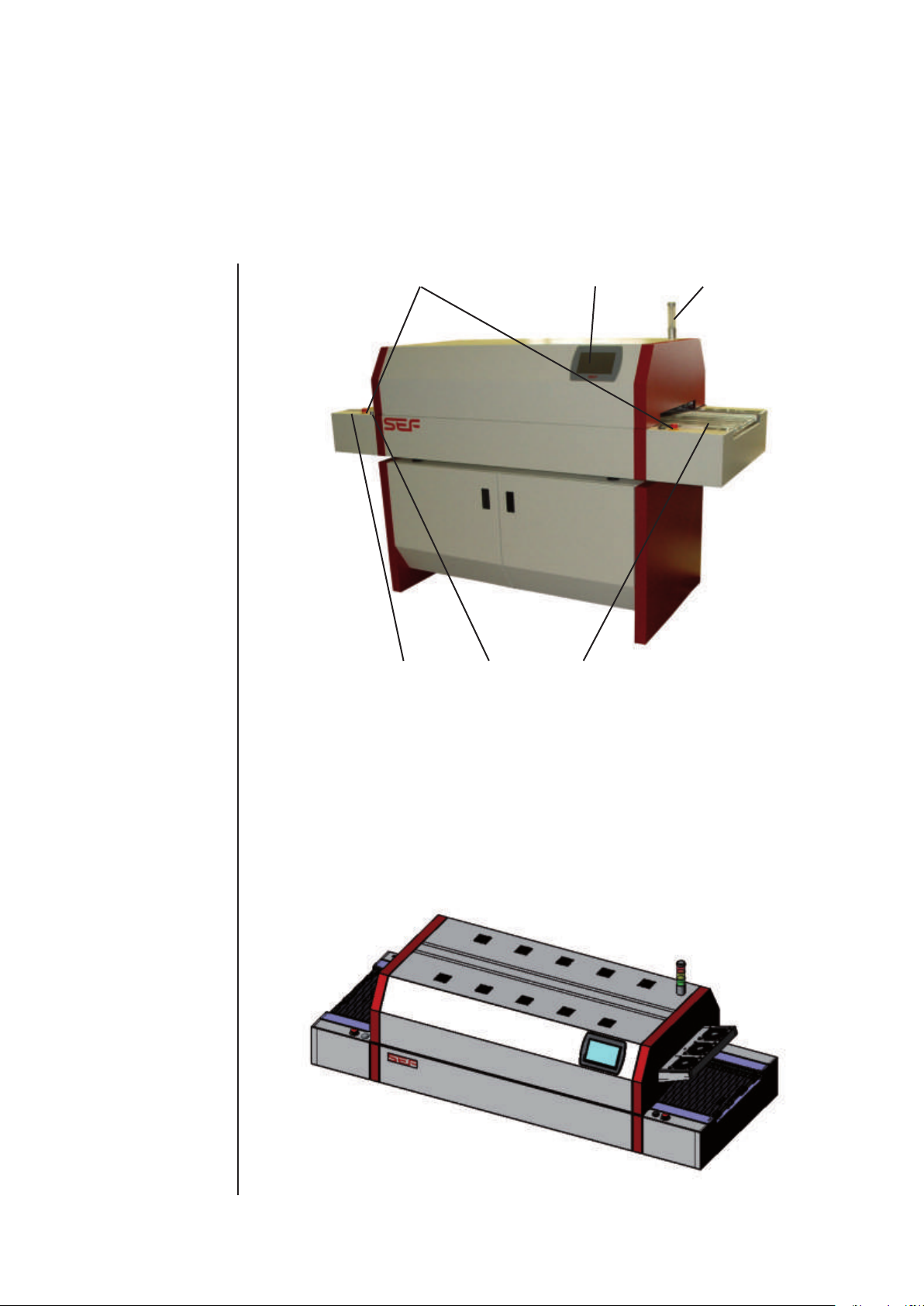
Working areas
Overview of working areas:
1Charging zone
2Emergency-stop switch
3 Operating switch On/Off
4Operating and programming via touch panel
5Lamp pole
6Discharging zone
1 3 6
2 4 5
2006
553 162,5
750
800
60
898
Reflowofen
1303-0A-BG-00-0
4.11.
1:10
A 2
-
Benennung:
+0,2
-0,3
Maßstab:
Format
Werkstoff:
Zeichnungsnummer
Blatt 1
Bl.
Allgemeintoleranzen
ISO 2768-mH
2014
Datum
Name
Tolerierung ISO 8015
Bearb.
Gepr.
Norm
Piepenbrink
Oberfläche:
SEF Systec GmbH
Kringelsburg
D-21379 Scharnebeck
Tel.: (04136) 909-0
-
Gewicht:
g
205212.11
551.10
Artikelnr.:
05199910
Prüfzeugnis
ja
nein
-0,1
This manual suits for next models
2
Table of contents
Other SEF Soldering Gun manuals


Popular Soldering Gun manuals by other brands


Aktakom
Aktakom ASE-1203 Operation and maintenance manual

Pace
Pace SODRTEK ST 125 Operation and maintenance manual

Weller
Weller wsd 81 operating instructions

jbc
jbc Precision B-iRON Station instruction manual

Kurtz Ersa
Kurtz Ersa CHIP TOOL operating instructions

Weller
Weller WE1010NA Original instructions