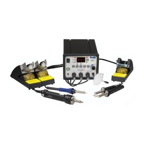
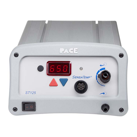
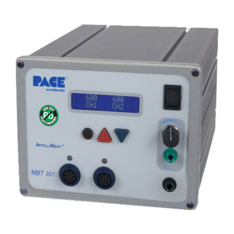
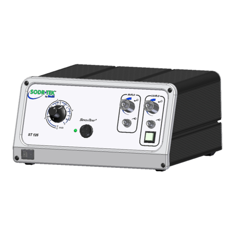
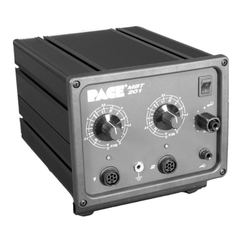
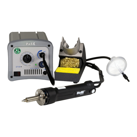
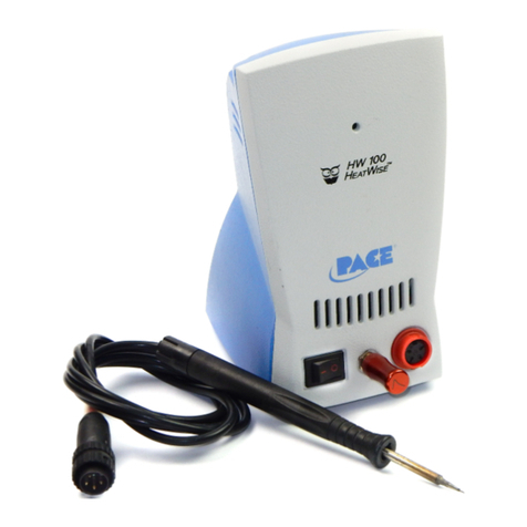
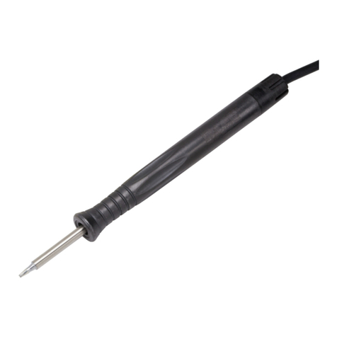
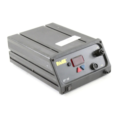
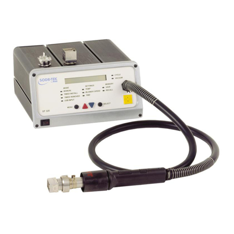
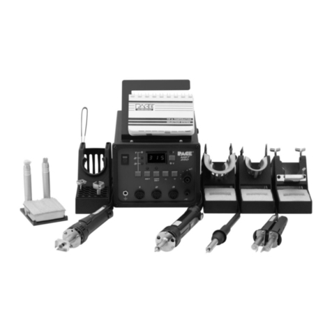
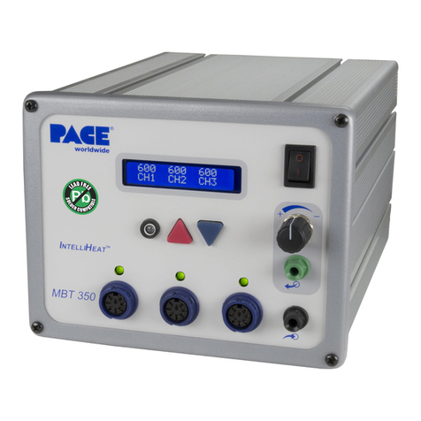
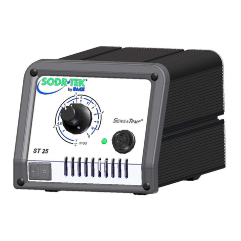
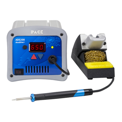
Pace SODRTEK ST 125 User manual

Operation and Maintenance Manual for
ST125 Soldering/Desoldering System
Manual 5050-0607
Rev. Date 6/14/22
This manual applies to:
Model Firmware
Revision
Required Power Part Number
ST125 w/SX-100 and Stand 1-2 120 VAC 8007-0607
ST125 w/SX-100 and Stand 1-2 230 VAC 8007-0608

TABLE OF CONTENTS
General Information................................................................................................................................................. 1
Introduction ......................................................................................................................................................... 1
Specifications ...................................................................................................................................................... 1
Temperature Specifications ................................................................................................................................ 1
Vacuum and Air Specifications ........................................................................................................................... 1
EOS/ESD Specifications ..................................................................................................................................... 1
Power Supply Features....................................................................................................................................... 2
Safety Guidelines .................................................................................................................................................... 2
System Set-Up......................................................................................................................................................... 3
Handpiece Power Connection ............................................................................................................................ 3
Handpiece Vacuum/Air Pressure Connection .................................................................................................... 3
System Power ..................................................................................................................................................... 4
Basic Operation....................................................................................................................................................... 5
Operation ............................................................................................................................................................ 5
LED Display ........................................................................................................................................................ 5
Digital Control Indicator LED............................................................................................................................... 5
Temperature Adjustment Display Mode ............................................................................................................. 6
Vacuum/Pressure Pump Operation .................................................................................................................... 6
Tip Offset............................................................................................................................................................. 6
Default Factory Settings...................................................................................................................................... 6
Customizing Your System ....................................................................................................................................... 7
Entering Set-Up Mode ........................................................................................................................................ 7
Password ............................................................................................................................................................ 7
Temperature Scale ............................................................................................................................................. 7
Temperature Limits ............................................................................................................................................. 7
Automatic Setback Timer .................................................................................................................................... 8
AutoOff ................................................................................................................................................................ 8
Exiting Set-Up Mode ........................................................................................................................................... 9
Corrective Maintenance ........................................................................................................................................... 9
Display Message Codes...................................................................................................................................... 9
Power Source...................................................................................................................................................... 9
Spare Parts.............................................................................................................................................................. 9
Service ................................................................................................................................................................ 9
PACE LIMITED WARRANTY STATEMENT...................................................................................................... 10

©2022 PACE Inc., Vass, North Carolina, All Rights Reserved Page 1
https://paceworldwide.com/
General Information
Introduction
Thank you for purchasing the ST125 Rework System. This manual will provide the information necessary to
properly set up, operate, and maintain your new system. Please read this manual thoroughly before using the
system.
The ST125 system is offered in either 120 VAC or 230 VAC versions. Each of these incorporate SensaTemp®
technology. The 230 VAC version systems bear the CE Conformity Marking, which assures the user that it
conforms to EMC 89/336/EEC. All models featured in this manual are lead free compatible and comply with
RoHS and WEEE directives.
This system meets the ANSI requirements for Soldered Electrical and Electronic Assemblies, J-STD-001.
Additionally, it will meet or exceed the requirements for electrostatic discharge set forth by ANSI/ESD S20.20.
Compliance with both standards is ensured by testing up to 50 MHz using the methodology described in
ANSI/ESD S13.1 2015.
Specifications
Input Power Requirements For 120V systems, 97-127 VAC at 50/60 Hz
For 230V systems, 197-253 VAC at 50/60 Hz
Dimensions 104 mm Hx 130 mm Wx 152 mm D
4.1”
H
x 5.1”
W
X 6”
D
Weight 2.3 kg (5 lbs.)
RoHS Compliant Yes
Control Technology SensaTemp®
Tip-to-Ground Resistance 2 Ohms or less
Temperature Accuracy Meets or Exceeds ANSI/J-STD-001
Temperature Range 38-482°C (100-900°F)
Temperature Specifications
Tip Temperature Range of 38 to 482°C (100 to 900°F).
Digital Readout Resolution: ±1° (°C or °F)
Tip Temperature Stability: ±1.1°C (2°F) while at idle.
Temperature Accuracy: Meets or exceeds ANSI/J-STD-001
Vacuum and Air Specifications
Vacuum Rise Time: Less than 200 milliseconds to pull 254mm/Hg (10 in/Hg) vacuum on a 33 cubic centimeter
(2 cubic inch) reservoir.
Vacuum: 880mbar (26 in. Hg.) Nominal
Pressure: 28 KPa (4 P.S.I.) Nominal MAXIMUM setting
Air Flow: 9 SLPM (0.32 SCFM) MAXIMUM
EOS/ESD Specifications
Tip-To-Ground Resistance: Less than 2 ohms.
AC Leakage: Less than 2 Millivolts RMS from 50 Hz to 100 MHz
Transient Level: Less than 500 mV peak, out to 100 MHz

©2022 PACE Inc., Vass, North Carolina, All Rights Reserved Page 2
https://paceworldwide.com/
Power Supply Features
Safety Guidelines
The following are safety precautions that personnel must understand and follow when using or servicing this
product.
1. POTENTIAL SHOCK HAZARD - Repair procedures on PACE products should be performed by qualified service
personnel. Line voltage parts may be exposed when the equipment is disassembled. Service personnel must avoid
contact with these parts when troubleshooting the product.
2. Tips and Heaters are hot when the handpiece is powered on and will remain so for a period of time after power off.
DO NOT touch the heater or the tip. Severe burns may result.
3. PACE Tip & Tool Stands are designed specifically for use with the associated handpiece and houses it in a manner
that protects the user from accidental burns.
4. Always use PACE systems in a well-ventilated area. Fume extraction systems, such as those available from PACE,
are highly recommended to help protect personnel from solder flux fumes.
5. Exercise proper precautions when using chemicals (e.g., solder paste or flux). Refer to the Material Safety Data
Sheet (MSDS) supplied with each chemical and adhere to all safety precautions recommended by the
manufacturer.
6. WARNING - The handpiece must be placed into the stand when not in use.
7. This equipment is not intended for use by persons (including children) with reduced physical, sensory or mental
capabilities, or lack of experience and knowledge, unless they have been given supervision or instruction
concerning use of the equipment by a person responsible for their safety.
Feature Description
A Program Button For access to program menu, presets, and confirmation of settings.
B Power Switch On/off control of power supply.
C Up Arrow Button Increase set temperature and scroll through program menu functions.
D Down Arrow Button Decrease set temperature and scroll through program menu functions.
E Power Receptacle Front panel connection of handpiece.
F Display Displays temperature setting and menu functions.
G Digital Control LED Indicates status of power supply.
H Air Pressure Assembly Consists of knob for adjusting amount of air pressure available from the
built-in port.
I Vacuum Port Provides vacuum for solder extraction and component handling tools.
J Foot Pedal Receptacle Connection point for optional foot pedal control.
K Ground Jack For grounding system to static safe work area.
L Power Inlet & Fuse Connection for IEC power cord and fuse replacement/storage.
H
I
A
B
C
D
G
E
F
J
K
L

©2022 PACE Inc., Vass, North Carolina, All Rights Reserved Page 3
https://paceworldwide.com/
System Set-Up
Set up the ST125 system by doing the following.
1. Remove the unit from its shipping container. Store the shipping container(s) in a convenient location.
Reuse of these containers will prevent damage if you ship or store the system.
2. Place the unit on a convenient workbench.
3. Ensure the POWER Switch (located on power source front panel) is in the "OFF" or
"0" position.
4. Inspect all system components, check for shipping damage, and ensure that all
purchased components (standard and optional) are present.
5. Assemble Tip & Tool Stands. Attach to the power source if desired using included hardware. Assembly
instructions are enclosed with each Tip & Tool Stand.
Handpiece Power Connection
The ST125 is designed to work with the SensaTemp SX-100 Solder Extractor, but any of PACE’s SensaTemp
hand tools can be used. Caution: Using handpieces from other product lines (e.g., IntelliHeat, AccuDrive,
HeatWise) may result in damage to your new equipment.
Connect the handpiece connector to the Power Receptacle in the following manner.
1. Align guide on connector
with slot on power
receptacle.
2. Insert connector into
power receptacle.
3. Turn the connector
housing clockwise to lock
in place.
Handpiece Vacuum/Air Pressure Connection
To set up your Sodr-X-Tractor air hose connection, perform the following steps:
1. Air Hose To Handpiece Connection:
a) Attach one end of the 137cm (54 in) length of air hose (P/N 1342-0015-08-
P1) to the metal tube in the back of the handpiece.
b) If you have a PACE system incorporating only one handpiece, attach the
air hose to the power cable using the supplied Hose Clamps (P/N 1321-
0085-01-P6). Space them evenly along the length of the power cable
starting at a point 6 inches from the ends of the handpiece.
c) If you have a PACE system incorporating 2 or more air handpieces, you may wish to leave the air
hose assembly unattached to allow a quick change to any air handpiece being used.
2. Prepare a VisiFilter in the following manner:

©2022 PACE Inc., Vass, North Carolina, All Rights Reserved Page 4
https://paceworldwide.com/
a) Connect a 5 cm (2 in) length of clear pvc air hose (P/N 1342-0001-01-P1) to the FLOW OUT of the
VisiFilter (P/N 1309-0028-P1); push and turn the hose onto the VisiFilter nipple to seat.
b) Insert the ribbed end of a male quick connect hose mount fitting (P/N 1259-0087-P1) into the free
end of the 5 cm (2 in) length of air hose connected to the FLOW OUT of the VisiFilter.
c) Connect the free end of the 137cm (54 inch) length of air hose to the FLOW IN of the VisiFilter.
d) Insert the end of the quick connect hose mount fitting (from the VisiFilter FLOW OUT) into the
power source Vacuum Port.
3. When using air pressure, and/or utilizing multiple air handpieces, PACE suggests the following alternative
set-up which utilizes some additional quick connect fittings.
a) Disconnect the 137cm (54 inch) length of air hose from the FLOW IN of the VisiFilter assembly.
Insert the ribbed end of a male quick connect hose mount fitting (P/N 1259-0087-P1) into the free
end of this air hose.
b) Connect the free end of another 5 cm (2 in) length of air hose (P/N 1342-0001-01-P1) with a female
quick connect fitting (P/N 1259-0086-P1) on it to the FLOW IN of the VisiFilter Assembly.
The 137cm (54 inch) length of air hose can now be easily moved between the VisiFilter Assembly and the
Controllable Pressure Port while the VisiFilter assembly remains connected to the Vacuum Port.
4. Additional fittings may also be added to the hose connection at the rear of each air handpiece
to ease changing of handpieces.
NOTE: When removing any air hose, turn and pull. Do not attempt to pull hose directly off. Damage or
breakage of fitting or VisiFilter may occur. Use your Sodr-X-Tractor with a clean VisiFilter element (P/N 1309-
0027-P10). Otherwise, a deterioration in performance or damage to the unit may occur.
System Power
1. Insert the female end of the power cord into the AC Power Receptacle on the rear panel of the power
source.
2. Plug the prong end (male end) of the power cord into an appropriate, grounded AC supply receptacle.

©2022 PACE Inc., Vass, North Carolina, All Rights Reserved Page 5
https://paceworldwide.com/
Basic Operation
Operation
1. Ensure the Set-Up procedure has been performed. Check for the following:
•Handpiece connection to the power source.
•Appropriate Tip is installed in handpiece.
•Power cord is connected to both an appropriate AC supply and the unit.
2. Turn the Power Switch On ("I").
3. After a brief start-up sequence, the Set Temperature will be displayed.
4. Adjust the tip temperature by pressing and holding Scroll Up ( ) Key or Scroll Down ( ) key. Observe
the display as the Set Temperature increases first in increments of 1° and then in increments of 10°.
When the desired temperature is reached, release the key.
5. NOTE: The Set Temperature can be adjusted only within the defined temperature limits. If the upper
limit has been reached, the display will read “HiL”; if the lower limit is reached, the display will read
“OFF”. Temperature limits can be adjusted in the Set-Up menu.
LED Display
The LED Display provides a 3-digit display of information. The display will show different things such as:
1. "888" on initial power up to ensure that all sections of the display are working.
2. The software version of the installed microprocessor (e.g., "1-9") for 2 seconds after the "888" is
displayed.
3. Actual temperature of the connected handpiece, during normal operation.
4. The displayed temperature will begin blinking (the indicator LED will also turn Amber) when the unit has
gone into Temperature SetBack.
5. "OFF" with stable display when the temperature set point has been adjusted beyond the Lower
Temperature Limit.
6. "OFF" with blinking display when the unit has entered AutoOff mode. Refer to page 7 for more
information.
Error messages "OSE" or “OCE” will appear if a system fault is detected. Refer to the "Corrective
Maintenance" portion of this manual.
Digital Control Indicator LED
The colored LED on the power source front panel indicates when the handpiece is
heating, has reached the set temperature, or if a fault has occurred.
LED Full On Red – A fault has occurred such as nothing is plugged into the
Power Receptacle on the front of the unit or the Heater Element of the connected
tool has an issue. Check installation of Heater Element on the handpiece as well
as the handpiece’s connection to the front panel.
LED Full On Green – The attached soldering tool has reached the Set
Temperature.
LED Full On Amber – The heater in the connected handpiece is functioning and
in process of heating up to the Set Temperature or may be cooling down to the
SetBack Temperature.
LED Off - Unit is not turned on or is in Auto ShutOff.

©2022 PACE Inc., Vass, North Carolina, All Rights Reserved Page 6
https://paceworldwide.com/
Temperature Adjustment Display Mode
The display will show the following when adjusting the desired Set Tip Temperature.
1. The Set Tip Temperature.
2. "HiL" (High Temperature Limit) when adjusting the set tip temperature and the
maximum allowable temperature is exceeded. Refer to the "Set-Up Mode" portion
of this manual.
3. "OFF" (Low Temperature Limit) when adjusting the set tip temperature and the
minimum allowable temperature is exceeded. Refer to the "Set-Up Mode" portion
of this manual.
Vacuum/Pressure Pump Operation
The PACE ST125 contains a vacuum pump that also provides air pressure. To activate, depress the activation button on
the connected handpiece. The ST125 has an optional foot pedal connector on the back, which can be used to activate
the pump instead of the switch on the handpiece.
Tip Offset
Differences between the temperature settings and true tip temperatures are negligible when using Thru-Hole,
single point soldering tips. With any heating system however, True Tip Temperatures can differ greatly from
temperature settings when using larger SMT soldering tips. Before adjusting offset, it is recommended to first
check the actual temperature of the tip using a Tip Temperature Monitor.
To adjust the temperature offset, hold the Program Key ( ) down for 5 seconds. The display will change to
show “000”. If the unit already has a Tip Offset than it will be shown in place of “000”. Use the keypad ( ) to
increase the temperature offset up to 83°C (150°F) hotter. When finished press the Program Key ( ) to return
to normal operation or, after 5 seconds of inactivity, the system will return to normal operation on its own
Default Factory Settings
Your new ST125 is equipped with several features which may be adjusted by the user. Listed below are the
factory settings of each. To learn about any of these features, refer to the applicable section of “Customizing
Your System” in this manual.
Feature Factory Setting
Password None Entered
Default Temperature Scale
(°C/°F)
°F for 115 VAC Systems
°C for 230 VAC Systems
“HI” Temperature Limit 427 °C (800 °F)
“LO” Temperature Limit 260 °C (500 °F)
SetBack Timer Enabled, 30 minutes
Auto Off Enabled, 60 minutes
Set Temperature 371 °C (700 °F)
Tip Offset 0 °C (0 °F)

©2022 PACE Inc., Vass, North Carolina, All Rights Reserved Page 7
https://paceworldwide.com/
Customizing Your System
The menu driven user interface of the systems allows you to easily customize your system. In Set-Up Mode,
you can:
•Enter, remove, or change a Password.
•Set the Default Temperature scale to °F or °C.
•Change the Upper and Lower Temperature limits.
•Enable the Temperature Setback feature and adjust the time-out period (if enabled).
•Enable or disable the Auto Off feature and adjust the time-out period (if enabled).
Entering Set-Up Mode
The following instructions should be performed to familiarize the operator with the system.
1. Place Power Switch in the “OFF” (“0”) position.
2. Press and hold the Program Key ( ) while turning the Power Switch on (“I” position). Release all keys
when the software version is displayed.
Password
3. The LED Display will show the version of the microprocessor and change to read “P- -” or "EP".
•
If the display reads "EP", a Password has been stored in system memory. The password must be
entered to access the menu. If the wrong password is entered, "no" will appear on the display and
the system will return to normal operation. If this occurs, repeat steps 1 & 2 and enter the correct
Password.
•Once the LED Display reads "P--". Choose one of the following options:
•Press the Program Key ( ) to keep the current password (even if there is no
password) and move on to the next setting or
•Set a password by selecting a 3-digit number using the keypad ( ). (1 to 999). Make a note of
the entered password for future reference. Selecting 000 and saving the changes will erase the
password to allow access to the menu without entering one. Press the Program Key ( ) to advance
to the next setting.
Temperature Scale
4. The display now shows the stored default Temperature Scale, either °C or °F.
Choose one of the following:
•Press the Program Key ( ) to keep the stored default Temperature Scale.
•Use the Scroll Up Key ( ) to change the default Temperature Scale.
•Press and release the Program Key ( ) to proceed to the next step
Temperature Limits
5. The display will show the stored default High ("Hi") Temperature Limit by alternating
to show "Hi" and the stored limit. Choose one of the following:
•Press and release the Program Key ( ) to keep the stored High
Temperature Limit.
•Adjust the stored High Temperature Limit using the keypad. ( ) Cannot
be adjusted below the Low Temperature Limit.
•Press and release the Program Key ( ) to proceed to the next step.

©2022 PACE Inc., Vass, North Carolina, All Rights Reserved Page 8
https://paceworldwide.com/
6. The display now shows the stored default Low ("Lo") Temperature Limit with the display alternating to
show "Lo" and the stored limit. Choose one of the following:
•Press and release the Program Key ( ) to keep the stored Low
Temperature Limit.
•Adjust the stored Lo Temperature Limit using the keypad. ( )
•Press and release the Program Key ( ) to proceed to the next step.
The full allowable temperature range of the ST125 is between 38°C (100°F) and 482°C (900°F). The Low
Temperature Limit cannot be adjusted higher than the High Temperature Limit. These limits control how high or
low the Set Temperature can be adjusted to during normal operation.
Automatic Setback Timer
To preserve tip life and save energy, the system can automatically adjust the tip temperature to 177°C (350°F)
after a selectable period of inactivity (factory setting of 30 minutes). There are 3 ways to exit Temperature
Setback; pressing the Scroll Up or Scroll Down keys ( ), flipping the power switch off then on again, or
holding the tip against a damp sponge. Upon exit of the Temperature Setback, the unit will resume normal
operations and the handpiece heat back up to the Set Temperature.
7. The display now shows the stored Automatic Setback time as "S-X" (x=0 thru 9).
Time is shown as tens of minutes (e.g., "S-3" equals 30 minutes). A display of "S-0"
indicates that Setback is disabled. Choose one of the following:
•Press and release the Program Key ( ) to keep the currently stored
Temperature Setback time.
•Adjust the stored Temperature Setback value using keypad. ( )
•Press and release the Program Key ( ) to proceed to the next step.
AutoOff
What is AutoOff? When enabled, the AutoOff safety feature turns off the power to the handpiece after a pre-
selected time (between 10- 90 minutes) from the system entering Temperature Setback. When the system has
entered Temperature Setback, a timer within the system circuitry will start running.
If any key is pressed during the selected time out period, the AutoOff and Setback timers are reset. The system
will return to normal operation. At the end of the time out period, the system will enter Auto Off. Power is turned
off to the heater and the display will show a flashing “OFF”. Exiting Auto Off: Auto Off can be exited; returning to
normal operation by pressing and releasing a Key (any of the 3 keys ), or by turning the Power Switch
OFF (“0”) and then back ON (“1”).
8. The display now shows the stored Auto Off time as "AOx" (x=0 thru 9). Time is
shown as tens of minutes (e.g., "AO8" equals 80 minutes). A display of "AO0"
indicates that Auto Off is disabled. Choose one of the following:
•Press and release the Program Key ( ) to keep the currently stored Auto
Off time.
•Adjust the Auto Off value using the keypad.
•Press and release the Program Key ( ) to proceed to the next step.

©2022 PACE Inc., Vass, North Carolina, All Rights Reserved Page 9
https://paceworldwide.com/
Exiting Set-Up Mode
9. The LED Display now reads "End". The Set-Up Mode procedure is now complete.
Choose one of the following steps:
•Press and release the Scroll Up Key ( ) to save the changes, exit the Set-Up
Menu and return to normal operation.
•Press and release the Scroll Down Key ( ) to return to the start of the Set-Up
Menu without saving any changes. Go back to step 3, Password Entry.
Corrective Maintenance
Display Message Codes
Display
Message Description
“no” The incorrect password has been entered. The displayed message will time out after
6 seconds and revert to normal operation. Enter the correct password.
“OCE” “Over Current Error” The Heater circuit is shorted or the handpiece has failed. Inspect
handpiece and heater element, replace as needed.
“OSE”
“Open Sensor Error” Unit is unable to sense the sensor from the handpiece. Make
sure handpiece is connected. Inspect handpiece and heater element for damage or
wear, replace as needed.
“OFF” The AutoOff feature has activated, turning off the handpieces. Press any button on
the unit to return to normal operation.
Power Source Issues
Most malfunctions are simple and easy to correct.
Symptom
Probable Cause
s
Solution
No power to system Blown Fuse
Replace the fuse (located in the AC
Receptacle Fuse Holder) with one of
the same rated value.
Handpiece will not heat
Defective Heater Element Refer to the appropriate handpiece
manual
Power Source Malfunction Contact PACE
Little to no vacuum or air
flow, heater works and
pump is running
Kinked air hose Inspect hoses and filters, move or
replace as needed.
Worn pump Replace vacuum pump
Full SodrTrap or VisiFilter Empty solder collection trap and
inspect VisiFilter element.
Spare Parts
Description PACE Part Number
Fuse 1 Amp, Time Lag (for 115V) 1159-0246-P5
Fuse 0.50 Amp, Time Lag (for 230V) 1159-0213-P5
Optional under shelf mounting bracket 1321-0609-P1
Pressure Knob assembly 1222-0081-P1
Service
Please contact PACE or your local distributor for service and repair.

©2022 PACE Inc., Vass, North Carolina, All Rights Reserved Page 10
https://paceworldwide.com/
PACE LIMITED WARRANTY STATEMENT
Limited Warranty
Seller warrants to the first user that products manufactured by it and supplied hereunder are free of defects in
materials and workmanship for a period of one (1) year from the date of receipt by such user. This Warranty as
applied to blowers, motor pumps, x-ray tubes, lenses, optical/lighting probes and cameras is limited to a period
of six (6) months. Monitors, computers and other brand equipment supplied but not manufactured by PACE are
covered under their respective manufacturer’s warranty in lieu of this Warranty.
This warranty does not cover wear and tear under normal use, repair or replacement required as a result of
misuse, improper application, mishandling or improper storage. Consumable items such as tips, heaters, filters,
etc. which wear out under normal use are excluded. Failure to perform recommended routine maintenance,
alterations or repairs made other than in accordance with Seller’s directions, or removal or alteration of
identification markings in any way will void this warranty. This warranty is available only to the first user, but the
exclusions and limitations herein apply to all persons and entities.
SELLER MAKES NO OTHER WARRANTY, EXPRESS OR IMPLIED, AND MAKES NO WARRANTY OF
MERCHANTABILITY OR FITNESS FOR A PARTICULAR PURPOSE.
Seller will, at its option, repair or replace any defective products at its facility or other locations approved by it at
no charge to user, or provide parts without charge for installation by the user in the field at user’s expense and
risk. User will be responsible for all costs of shipping equipment to Seller or other location for warranty service.
EXCEPT FOR THE REMEDY ABOVE DESCRIBED, UNLESS OTHERWISE REQUIRED BY APPLICABLE
LAW, SELLER WILL HAVE NO OTHER OBLIGATION WITH REGARD TO ANY BREACH OF WARRANTY OR
OTHER CLAIM WITH RESPECT TO THE PRODUCTS, OR LIABILITY FOR ANY DIRECT, INDIRECT,
CONSEQUENTIAL, OR INCIDENTAL LOSS OR DAMAGE CAUSED BY OR OCCURRING IN CONNECTION
WITH ANY OF THE PRODUCTS.
Warranty service may be obtained by contacting the appropriate PACE Company or local Authorized PACE
distributor as set forth below to determine if return of any item is required, or if repairs can be made by the user
in the field. Any warranty or other claim with respect to the products must be made with sufficient evidence of
purchase and date of receipt, otherwise user’s rights under this warranty shall be deemed waived.
PACE Incorporated retains the right to make changes to specifications contained herein at any time, without
notice. Contact your local authorized PACE Distributor or PACE Incorporated to obtain the latest specifications.
The following are trademarks and/or service marks of PACE, Incorporated Vass, NC USA: AccuDrive®, Arm-
Evac®, Cir-Kit®, ConducTweez™, Flo-D-Sodr®, HandiPik™, IntelliHeat®, LapFlo™, Mini-Wave®, MiniTweez®
, PACE®, PACE EUROPE®, PACE WORLDWIDE®, PACENTER®, Pik-Tip®, PikVac™, Redi-Rak™,
ResisTweez™, SensaTemp®, SMR®, Snap-Vac®, SodrTek®, Sodr-X-Tractor®, StripTweez™, Thermo-
Drive®, ThermoFlo®, ThermoJet®, ThermoPart™ ThermoPik™ and ThermoTweez®, VisiFilter™.
PACE products meet or exceed all applicable military and civilian EOS/ESD, temperature stability and other
specifications including MIL STD 2000, ANSI/JSTD 001, IPC7711, and IPC A-610.
PACE Incorporated
346 Grant Road
Vass, NC 28394
Tel: (877) 882-PACE
Tel: (910) 695-7223
Fax: (910) 695-1594
Other manuals for SODRTEK ST 125
1
Table of contents
Other Pace Soldering Gun manuals

Pace
Pace ST 25 User manual

Pace
Pace ST 85 Manual

Pace
Pace WJS 100 User manual

Pace
Pace Sodrtek HW50 User manual

Pace
Pace SODRTEK ST 125 User manual

Pace
Pace ST 65 Manual

Pace
Pace MicroBenchtop MBT-100 Troubleshooting guide

Pace
Pace Sodr-X-Tractor SX-80 User manual

Pace
Pace ST 25 User manual

Pace
Pace MBT250E-SDSoftGround Instruction manual