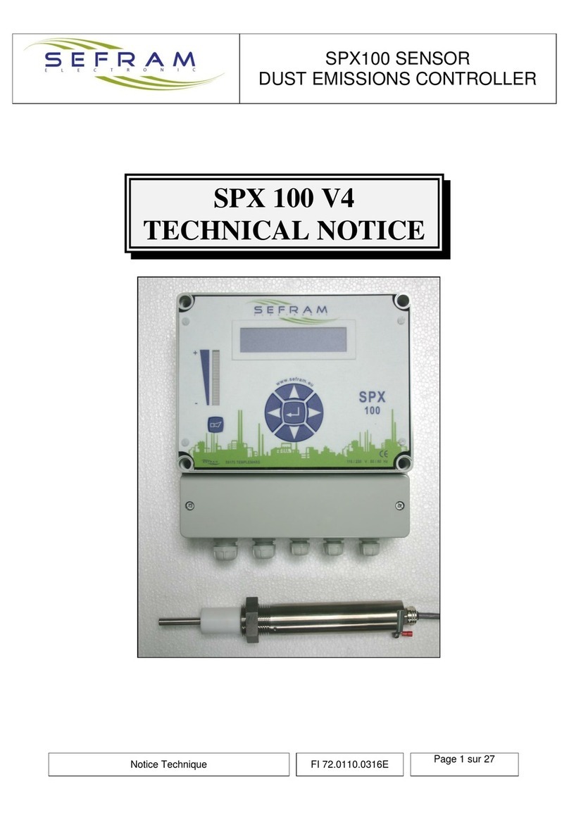
SEFRAM SFX+NETWORK User manual

Technical Data Sheet
FI 72.0239.0320E
Page 1 / 108
SEQUENCER CONTROLLER
SFX+ NETWORK
TECHNICAL NOTICE
PLACE GUTENBERG - 59175 TEMPLEMARS (France)
Tel: +33(0)3 20 60 49 49 - Fax: +33(0)3 20 95 59 62
Email: contact@sefram.eu Web: www.sefram.eu
ELECTRONICS DEDICATED TO DEDUSTING
AND AIR QUALITY
2006 SEFRAM
All rights reserved. Made in France.

Technical Data Sheet
FI 72.0239.0320E
Page 2 / 108
CONTENTS
I –GENERAL DETAILS (page 4)
II –GENERAL SPECIFICATIONS MAIN BOX (page 6)
III –CONSTITUTION OF THE SFX+ NETWORK (page 7)
IV –CU CARD (page 8)
V –THE VARIOUS PLUG-IN MODULES (page 14)
- COMMON CHARACTERISTICS (page 14)
- POWER MODULE (page 17)
- MODULE: 4 AON INPUTS (*)
4 RELAY OUTPUTS (*) (page 20)
- 8 AON INPUTS MODULE (*) (page 23)
- 8 RELAY OUTPUTS MODULE (*) (page 25)
- 8 AC OUTPUTS MODULE (*) (page 27)
- 8 DC OUTPUTS MODULE (*) (page 30)
- TRANSFER MODULE (*) (page 33)
- FILTER MODULE (page 36)
- SFX+ MODULE POWER CONSUMPTION (page 37)
VI –SLAVE BOXES (page 39)
VII –MDPP2000 BOX (page 41)
VIII –THE MENUS (page 42)
- THE SELECT MENU (page 42)
- LANGUAGE (page 43)
- CODE (page 44)
- NUMBER OF WAY (page 46)
- NUMBER OF CELL. (page 46)
- Adjusting the times (page 47)
- NB CYCLES STOP FAN (*) (page 49)
- STOP TYPE (page 50)
- NB SIMULTAN. PULSES (*) (page 51)
- NB STEP ONLINE (*) (page 53)
- ONLINE CYCLE (*) (page 54)
- NB STEP OFFLINE-WAY (*) (page 56)
- OFFLINE-WAY CYCLE (*) (page 57)
- NB STEP OFFLINE-CELL (*) (page 58)
- OFFLINE-CELL CYCLE (*) (page59)
- A/C THRESHOLD (*) (page 60)
- DP THRESHOLD (*) (page 62)
- DATE/TIME (page 63)
- OUTPUTS NAME (page 64)
- MODBUS COM. (page 65)
- PC COM. (page 66)
- NB. FLT. DUST. EMISS. (*) (page67)
- CONFIG. SAVE (page 68)
- CONFIG. RESTORE (page68)
-OPEN/CLOSE CONTROL (*) (page 69)
-DUST INPUT TYPE (*) (page 69)

Technical Data Sheet
FI 72.0239.0320E
Page 3 / 108
- THE VISU MENU (page 70)
- CYCLE (page 71)
- A/C MEASURES (page 72)
- FAULTS (page 73)
- COUNTS (page 74)
- IINFOS (page 74)
- HISTORICAL (page 75)
- THE MANU MENU (page 78)
- MANUAL RUNNING (page 78)
- DURING X CYCLES (page 79)
- OUTPUT FORCING (page 80)
- CYCLE POSITION (*) (page 81)
IX –OPERATION (page 82)
- ON LINE (*) (page 83)
- OFF LINE (*) (page 84)
- PUT ON SERVICE (*) (page 86)
X –FAULT CONTROLS (page 87)
- ELECTRICAL FAULT CONTROLS (page 88)
- CELL OPENING / CLOSING FAULT CONTROL (*) (page 90)
- MINI PRESSURE FAULT (*) (page 91)
- DUST REMOVAL SOLENOID VALVE NOT OPEN PRESSOSTATIC FAULT (*) (page 92)
- RE-INFLATION FAULT (*) (page 93)
- DUST EMISSION FAULT (*) (page 94)
- DIALOG. FAULT (page 96)
XI –GENERAL INSTRUCTIONS FOR THE USER (page 97)
XII –MAINTENANCE (page 97)
ANNEXES:
-MODBUS EXCHANGE TABLE (page 98)
-SLAVES BOXES : CONNECTIONS
FUSES AND CODE
-SPECIFICITY…
(*) These sections are in option –The customer has only to take in consideration the chosen options.

Technical Data Sheet
FI 72.0239.0320E
Page 4 / 108
I - GENERAL DETAILS
The SFX+ NETWORK is a compact and modular sequencer dedicated to dust removal and checking and
monitoring the filtration / dust removal process.
The modular design of its hardware and software means that it can be configured rationally to fulfil the
most diverse applications.
It can manage filters organised into several cells (=compartments) and with several compressed air
headers (=reservoirs).
- The SFX+ controls: - Dust removal cycles in ONLINE or OFFLINE mode
- Associated controls
- Monitoring / recording of events: Log
The SFX+ includes the operating program as standard. Only the operating parameters can be accessed
and adjusted by the user.
Easy to use adjustments with drop down menus, graphical display or PC with the « SfxPlusReseauParam
SVx.x » software.
The SFX+ NETWORK has several communication ports RS232/RS485/RS422 for external
communication. Easy to integrate into all processes, the SFX+ NETWORK can communicate in various
ways:
- By PC and secure BUS
- By MODBUS protocol
- Gateway PROFIBUS or other available (consult us)
- By MODEM, GSM for interrogation / remote access
The SFX+ NETWORK can consist of several boxes (main box + slave boxes) interconnected on a bus of
type RS422 with computer security protocol. A configuration in the form of a bus means the cabling can
be reduced compared with the classic configuration. Indeed, the slave boxes can be placed close to the
filter cleaning solenoid valves whilst collecting the information required for a good filter clean
(compressed air pressure, cell positions) and while pilotingthe cell and header isolations.

Technical Data Sheet
FI 72.0239.0320E
Page 5 / 108
Main box:
Up to 99
Slave boxes:
1 MDPP2000 box:
The SFX+ NETWORK configuration flexibility is not just limited to filtration / dust removal applications
(please contact us).
A box consists of up to 18
solenoid valve (EV) outputs
with or without:
- mini pilot
- compressed air pressure
switch (Pressostat)
- cell/tank isolation
management
- cell position control
Pressure switch
Loss of load
Remote monitoring
Printer

Technical Data Sheet
FI 72.0239.0320E
Page 6 / 108
II –GENERAL SPECIFICATIONS MAIN BOX
Customer power supply According configuration
24/48V or 115/230V AC 50/60 Hz
Insulation through internal transformer
24/48V DC
Isolated DC/DC converter recommended
General protection By 5x20 fuse on the power supply module and
on the filter module
Output protection Individual by 5x20 fuse on the modules
Operating temperature 0° to 60° C (room temperature: 45° C)
Storage temperature - 20° to 80° C
Presentation In a box or cabinet
Minimum IP55
Electrical / cable output connections To be made in line with specifications

Technical Data Sheet
FI 72.0239.0320E
Page 7 / 108
III –CONSTITUTION OF THE SFX+ NETWORK
Main box SFX+ NETWORK must comprised:
-1 CU card (Central Processing Unit)
-1 power supply module
-2 filter modules
The following modules can be added to this main box to form the required sequencer.
- Module with 8 AC outputs (triacs)
- Module with 8 DC outputs (transistors)
- Module with 8 relay outputs
- Module with 4 AON inputs and 4 relay outputs
- Module with 8 AON inputs
- Transfer module: end of line or start of line
Connected to this main box, according to the required sequencer, can be added :
-slave boxes
-MDPP2000 box
Simple configuration example:
SFX+ 40 ON LINE SV / 1 operating order / Operating response / SV fault transfer
Representing 1 POWER SUPPLY module
1 module with 4 inputs / 4 outputs
5 AC output modules
Maximum configuration:
- Output modules: 64 (representing 512 outputs)
- Input modules: 32 (representing 256 inputs)
- Total dust removal S.V.: 512
- Dust removal S.V. by cell: 99
- Cells: 32
- Tanks: 32
- Slave boxes: 99
All modules combined, the SFX+ NETWORK can control 99 modules (line transfer module to be
controlled + supply regeneration, please contact us).

Technical Data Sheet
FI 72.0239.0320E
Page 8 / 108
IV –CU CARD
The CU card (Central Unit) controls all of the modules, slaves and outside communication. It acts as the
SFX+ / user interface via its front panel.
CHARACTERISTICS
Consumption 0.9A under 5V
Calendar 11 years retention (de-energized)
Precision +/- minute per month maximum.
Leap year management
Saving of data/ parameters/ settings by 2 batteries of type R6
2 years retention (de-energized)
Card Ref.: « UCSUP »
THE FRONT PANEL
Warning leds
Navigator
Adjustment / menu
Graphical
display
Function buttons
Menu input

Technical Data Sheet
FI 72.0239.0320E
Page 9 / 108
THE NAVIGATOR
The buttons on the navigator are used to move within the menus, to
adjust parameters and to validate data.
THE BUTTONS
RUN / STOP button: - RUN: SFX+ operation authorisation
- STOP: stop dust removal. Reinitialise graphs
SELECT button: used to enter the "SELECT" menu
(adjustment of parameters)
VISU button: used to enter the "VISU" button
RESET button: used to reset faults locally
MANU button: used to enter the "MANU" menu
CONTRAST button: used to adjust the contrast of the graphical display.
- 1st press on the button + holding it pressed = contrast increased
- Button released
- 2nd press on the button + holding it pressed = contrast decreased
Left
Down / -
Right
Up / +
Valid

Technical Data Sheet
FI 72.0239.0320E
Page 10 / 108
GRAPHICAL DISPLAY / SIGNALLING LEDS
The graphical display is of STN LCD type with LED backlighting. The contrast is adjusted automatically
as a function of usage temperature.
By defect, the display shows:

Technical Data Sheet
FI 72.0239.0320E
Page 11 / 108
CONNECTION
4 computer connections are available on the CU (named COM1 to COM4):
-COM1: reserved for the link to the modules
o7 pin connector
-COM2: reserved for the link to the PC (direct or via MODEM)
o3 pin connector (for link type RS232)
o4 pin connector (for link type RS485/RS422)
ocabling on one OR other
-COM3: reserved for the link to customer (MODBUS)
o3 pin connector (for link type RS232)
o4 pin connector (for link type RS485/RS422)
ocabling on one OR other
-COM4: reserved for the link to SEFRAM devices (slaves boxes / MDPP2000)
o4 pin connector (for link type RS422)
visu of the inside of the cabinet /main box, back of the UC:

Technical Data Sheet
FI 72.0239.0320E
Page 12 / 108
Remark:
When you are in the display by defect, the RIGHT navigator button allows the activity on the
communication ports to be displayed. The corresponding LEDs light up each time information is
received:
Example of a MDPP2000 and several slave boxes connection:
Remarks: -the last box placed on the bus must be equipped with a load
(the load is plugged in to the coupling connector)
- If there are more than 32 devices on the bus, the signal must be regenerated
(consult us)
Remark for devices connected in RS485 (1 pair) :
Terminals RA/TA
and RB/TB
must be connected

Technical Data Sheet
FI 72.0239.0320E
Page 13 / 108
Cabling between CU card and a PC:
BATTERY REPLACEMENT
All of the settings/parameters and the history record are stored in memories safeguarded by two batteries
of type R6. Remove the central unit protection lid to gain access to these.
TAKE CARE WITH THE DIRECTION
The batteries enable the data to be retained for an estimated period of two years if the central unit card is
not powered (the period can vary depending on the power of the batteries used: calculated with 1.5Ah
batteries.
We recommend the periodic replacement of the batteries (once 2 years):
The batteries can be replaced with the powered central unit card: there will be no data loss. In this event,
take the necessary precautions (do not touch the electronic parts, the printed circuit tracks etc.).
If the central unit card is not powered, (the fact of) removing the batteries involves the loss of all of the
data/settings/parameters. The steps on the SELECT menu « SAVE CONFIG. » and « RESTORE
CONFIG. » can be used in this event: the settings/parameters are then recovered but the historical records
are lost nevertheless.
BATTERY R6 TYPE

Technical Data Sheet
FI 72.0239.0320E
Page 14 / 108
V –DIFFERENTS PLUG-IN MODULES
COMMON CHARACTERISTICS
Apart from the filter module mounted directly on the back panel, all the other modules can be plugged
onto the 35 mm symmetrical DIN rail.
ACCESS TO THE CONNECTIONS
The connection terminals are accessed by opening the door of the module.
A connection label specific to each type of module is affixed to the back of
the door.
To facilitate the connections, the door can be removed.
Warning: always refit the door to the module when it has been removed
DISASSEMBLY / ASSEMBLY
Warning: Refer to the general safety precautions.
With the SFX+ NETWORK off
DISASSEMBLY:
1) Disconnect the jumper A
2) Disconnect the connection terminals
Remove the wire bundle from the module
3) Pivot the module upwards and release it from the rail.
A

Technical Data Sheet
FI 72.0239.0320E
Page 15 / 108
ASSEMBLY:
1) Whilst holding the module, Position the fixed slot of the module on the
upper edge of the rail
2) Pivot the module downwards, holding it against the rail.
3) Reconnect the jumper A and the connection terminals
A

Technical Data Sheet
FI 72.0239.0320E
Page 16 / 108
REMOVING THE DOOR
With the door open, press slightly on the bottom of the module. Release the door starting with the lower
hinge pin.
REFITTING THE DOOR
Release the bottom of the module by pressing slightly and insert the top pin then the bottom pin.
ACCESS TO THE FUSES
All the outputs are individually protected by 5x20 fuses. These fuses are accessed via the opening on the
right hand side of the module.
The supply module consists of four 5x20 fuses (rating: see supply
module) which can also be accessed on the right hand side of the module
after having removed the cover (clipped on).

Technical Data Sheet
FI 72.0239.0320E
Page 17 / 108
POWER MODULE
MAIN SPECIFICATIONS
Module reference: SFX+ ALIM
Module supply: 24V 50/60 Hz
Or 24V DC
Supply to the relays, input, outputs and modules via the power module.
Input: 24V 50/60 Hz
24V DC
The power module supplies all of the modules with +5V
Fan-out of the +5V: 2 A
Protection: by 5x20 fuse on the module supply and input and relay output supply.
Insulation: no insulation between U input and +5V
no insulation between supply input, relay input/output and the corresponding output.
SIGNALLING
ILLUMINATED FIXED
MODULE
IDENTIFICATION

Technical Data Sheet
FI 72.0239.0320E
Page 18 / 108
CONNECTIONS
TO CU MODULE
SUPPLY AND INTERNAL BUS
INTERNAL 5V TRANSFER FOR
START OF LINE SUPPLY
24V 50/60Hz OR 24V DC MODULE SUPPLY
OUTPUT 24V DC FOR SUPPLY TO
INPUTS AND RELAY MODULES
INPUT 24V 50/60Hz OR 24V DC FOR SUPPLY TO
INPUTS AND RELAY MODULES

Technical Data Sheet
FI 72.0239.0320E
Page 19 / 108
FUSES LOCATIONS
F1, F2: supply protection fuses
Module size 5x20 glass, rating 1A type F
F3, F4: supply protection fuses of the input and relay output modules
Size 5x20 glass, rating 1A type F

Technical Data Sheet
FI 72.0239.0320E
Page 20 / 108
MODULE: 4 AON INPUTS
4 RELAY OUTPUTS
GENERAL SPECIFICATIONS
- Module reference: SFX+ 4E –4S
INPUTS
- N° of inputs per module: 4
- Input voltage: 24V DC
- Current for 1 input: 13 mA at 24V
- Input impedance: 2.7 K
- Input seen at 1 at U 13.5V I = 4.5 mA at 13.5V
- Response time: configurable from 1/100 - 255/100 seconds (SEFRAM adjustment)
- Input type: resistive
- 2 and 3 wire proximity detector compatibility: yes (contact us)
- Common of the inputs to + 24V
- Insulation: between input and internal logic: 2000V AC 1 minute
insulation resistance: > 10 M
type: by optocoupler
- Protection: 24V DC by two 5x20 fuses on the power module
OUTPUTS
- N° of outputs per module: 4
- Max operating voltage: 250V AC
- Nominal current: 4A AC1 (per way)
- Nominal cut-off power (ohmic load): 2000 VA
- Max load for direct current: ohmic load 4A 38V DC 1.5A 48V DC
inductive load (L/R = 20 ms) 0.4A 34V DC
0.2A 48V DC
- Make / break response time: < 10 ms
- Type of contact: closing
- Output protection: none –fit a quick cut-off fuse
per way or group of ways so as to limit it to In max per way
- Insulation: input output and internal logic: 2000V AC 1 minute
insulation resistance > 10 M
- Mechanical life length: > 30x106operations (depending on load)
Table of contents
Other SEFRAM Controllers manuals
Popular Controllers manuals by other brands
ETI
ETI PFC 6 RS User and service manual
Johnson Controls
Johnson Controls TEC3010 installation instructions

Auber Instruments
Auber Instruments SYL-3615 instruction manual
DIG
DIG ECO1 MVA instruction manual

Xylem
Xylem CentriPro MP PLUS Installation, operation and maintenance manual
Emerson
Emerson Bettis SMART EHO G Series Service instructions
