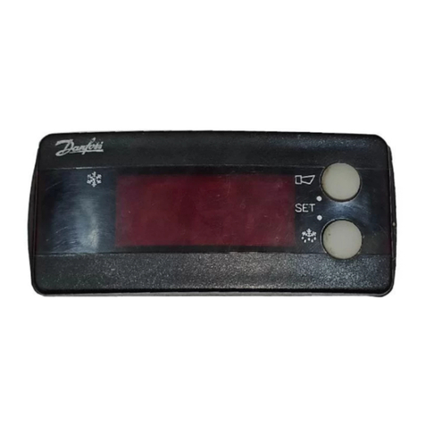
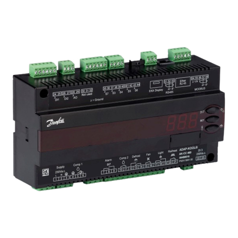
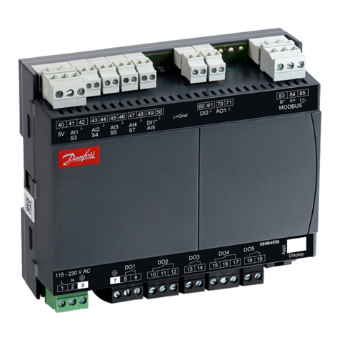
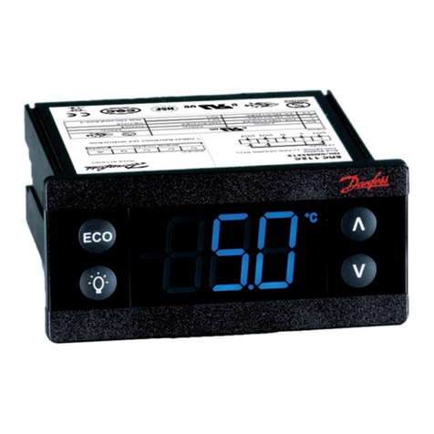
Light-emitting diodes (LED) on front panel
There are LED’s on the front panel which will light up when the
corresponding relay is activated.
The three lowest LED’s will ash, if there is an error in the regula-
tion.
In this situation you can upload the error code on the display and
cancel the alarm by giving the uppermost button a brief push.
Display
The values will be shown with three digits, and with a setting you
can determine whether the temperature is to be shown in °C or in
°F.
Operation Menu survey
The controller can give the following messages:
E1
Error message
Errors in the controller
E7 Cut-out Sair
E8 Shortcircuited Sair
E11 Valve’s actuator temperature outside its range
E12 Analog input signal is outside the range
A1 Alarm message High-temperature alarm
A2 Low-temperature alarm
The buttons
When you want to change a setting, the two buttons will give you
a higher or lower value depending on the button you are push-
ing. But before you change the value, you must have access to the
menu. You obtain this by pushing the upper button for a couple
of seconds - you will then enter the column with parameter codes.
Find the parameter code you want to change and push the two
buttons simultaneously. When you have changed the value, save
the new value by once more pushing the two buttons simultane-
ously.
Gives access to the menu
(or cutout an alarm)
Gives access to changes
Saves a change
Examples of operations
Set set-point
1. Push the two buttons simultaneously
2. Push one of the buttons and select the new value
3. Push both buttons again to conclude the setting
Set one of the other menus
1. Push the upper button until a parameter is shown
2. Push one of the buttons and nd the parameter you want to
change
3. Push both buttons simultaneously until the parameter value is
shown
4. Push one of the buttons and select the new value
5. Push both buttons again to conclude the setting Factory setting
If you need to return to the factory-set values, it can be done in this way:
- Cut out the supply voltage to the controller
- Keep both buttons depressed at the same time as you recon nect the supply voltage
Function Para-
meter Min. Max. Fac.
setting
Normal display
Shows the temperature at the selected sensor
At ICM valve OD also can be selected -°C
Reference
Set the required room temperature - -70°C 160°C 10°C
Temperature unit r05 °C °F °C
Input signal’s temperature inuence r06 -50°C 50°C 0.0
Correction of the signal from Sair r09 -10,0°C 10,0°C 0.0
Correction of the signal from Saux r10 -10,0°C 10,0°C 0.0
Start/stop of refrigeration r12 OFF/0 On/1 On/1
Alarm
Upper deviation (above the temperature setting) A01 0 50 K 5.0
Lower deviation (below the temperature setting) A02 0 50 K 5.0
Alarm’s time delay A03 0 180
min 30
Regulating parameters
Actuator max. temperature n01 41°C 140°C 140
Actuator min. temperature n02 40°C 139°C 40
Actuator type (1=CVQ-1 to 5 bar, 2=CVQ 0 to 6
bar, 3=CVQ 1.7 to 8 bar, 4= CVMQ, 5=KVQ, 6= ICM) n03 1 6 2
P: Amplication factor Kp n04 0,5 50 3
I: Integration time Tn (600 = o) n05 60 s 600 s 240
D: Dierentiation time Td (0 = o) n06 0 s 60 s 10
Transient phenomenon
0: Ordinary control
1: Underswing minimised
2: No underswing
n07 0 2 2
OD - Opening degree - max. limit - ICM only n32 0% 100% 100
OD - Opening degree min limit - ICM only n33 0% 100% 0
Miscellaneous
Controller's address (0-120) o03* 0 990 0
ON/OFF switch (service-pin message) o04* - -
Dene output signal of analog output:
0: no signal, 1: 4 - 20 mA, 2: 0 - 20 mA o09 0 2 0
Dene input signal of analog input
0: no signal, 1: 4 - 20 mA, 2: 0 - 20 mA o10 0 2 0
Language (0=english, 1=German, 2=French,
3=Danish, 4=Spanish and 6=Swedish.)When you
change the setting to an other language you must
activate o04 before "the new language" can be
visible from the AKM program.
011* 0 6 0
Set supply voltage frequency o12 50
Hz/0
60
Hz/1 0
Select of running display value o17 Au/0 Air/1 Air/1
(Setting for the function o09)
Set the temperature value where the output signal
must be minimum (0 or 4 mA)
o27 -70°C 160°C -35
(Setting for the function o09)
Set the temperature value where the output signal
must be maximum (20 mA)
o28 -70°C 160°C 15
Service
Read temperature at the Sair sensor u01 °C
Read regulation reference u02 °C
Read temperature at the Saux sensor u03 °C
Read valve's actuator temperature u04 °C
Read reference of the valve's actuator temperature u05 °C
Read value of external current signal u06 mA
Read value of transmitted current signal u08 mA
Read status of input DI u10 on/o
ICM opening degree. (only at ICM) u24 %
*) This setting will only be possible if a data communication module has been
installed in the controller.
SW =1.5x
