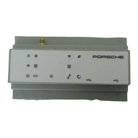
Porsche Home Energy Manager User manual

Porsche Home Energy Manager
9Y0.915.686/.A/.B/.C/.D/.E
9Y0.071.723.A-ROW

US Porsche Home Energy Manager
Installation Manual...............................1
FC Porsche Home Energy Manager
Manuel technique .............................20
ESM Porsche Home Energy Manager
Installation Manual............................40
PTB Porsche Home Energy Manager
Manual de instalação ........................60
TR Porsche Home Energy Manager
Kurulum Talimatları ...........................80
RU Porsche Home Energy Manager
Инструкция по установке..............99
UK Porsche Home Energy Manager
Посібник зі встановлення........... 119
VIE Porsche Home Energy Manager
Hướng dẫn lắp đặt................... 139
HE Porsche Home Energy Manager
xxxxxxxxxxx.................................... 160
AR Porsche Home Energy Manager
xxxxxxxxx........................................ 179
JPN Porsche Home Energy Manager
xxxxxxxxxxxxxxxxxx.................... 198
KOR Porsche Home Energy Manager
xxxxxxxxxx...................................... 217
CHS Porsche Home Energy Manager
xxxxxxxx .......................................... 236
CHT Porsche Home Energy Manager
xxxxxxxx .......................................... 255
THA Porsche Home Energy Manager
I........................................................... 273
Ҿጎ֩
৾ັζΣνͺσ
ʤʰʷʺʤʪʩʸʣʮ
¼n¤º°µ¦·´Ê
Ԋ၆Йы
설치 설명서
9Y0071723A_ROW.book Page 1 Tuesday, July 21, 2020 3:04 PM

1
Contents
English (USA)
Referenced Documents ................................................3
Safety Principles ............................................................3
Qualification of Personnel................................................3
Notes on Installation .........................................................3
Overview ..........................................................................4
Installation Variant 1.........................................................4
Installation Variant 2.........................................................5
Installation Variant 3.........................................................5
Connection Diagram..........................................................6
Display Elements and Controls.......................................7
Device Connections Overview........................................8
Installation and Connection .........................................8
Plug Connector Overview ................................................8
Connection to the Power Grid .....................................11
Connection to the Building Installation..................... 12
Connecting to the Device .............................................13
Getting Started ............................................................ 13
Setup .............................................................................14
Opening the Web Application via the Hotspot .......14
Running the Setup Assistant ....................................... 14
Checking Function..........................................................15
Production Information .............................................17
Declaration of Conformity ............................................ 17
Technical Data .............................................................18
Index ..............................................................................19
9Y0071723A_ROW.book Page 1 Tuesday, July 21, 2020 3:04 PM

2
US
FC
ESM
PTB
TR
RU
UK
VIE
HE
AR
JPN
KOR
CHS
CHT
THA
Dr. Ing. h.c. F. Porsche AG is the owner of numerous
trademarks, both registered and unregistered,
including without limitation the Porsche Crest®,
Porsche®, Boxster®, Carrera®, Cayenne®, Cayman®,
Macan®, Panamera®, Spyder®, Tiptronic®, VarioCam®,
PCM®, PDK®, 911®, 718®, RS®, 4S®, 918 Spyder®,
FOUR, UNCOMPROMISED®, and the model numbers
and the distinctive shapes of the Porsche
automobiles such as, the federally registered 911
and Boxster automobiles. The third party trademarks
contained herein are the properties of their
respective owners. All text, images, and other
content in this publication are protected by
copyright. No part of this publication may be
reproduced in any form or by any means without prior
written permission of Porsche Cars North America,
Inc. Some vehicles may be shown with non-U.S.
equipment. Porsche recommends seat belt usage
and observance of traffic laws at all times.
© 2019 Porsche Cars North America, Inc.
Installation instructions
Please keep these installation instructions in a safe
place.
These instructions are intended for those persons
tasked with the installation, commissioning and
maintenance of the energy manager or who are
responsible for this.
Always observe and abide by the warnings and
safety instructions set out in these instructions.
The manufacturer assumes no liability in the event
of improper handling that contravenes the
information in these instructions.
Moreover, the approval conditions of the supplied
accessory parts must also be observed and
complied with.
Further instructions
Information on using the energy manager is provided
in the operating instructions. Pay particularattention
to the warning and safety instructions.
The instructions for the web application can be found
at https://www.porsche.com/international/
aboutporsche/e-performance/help-and-contact/
For other languages, select the desired country
version of the website.
Suggestions
Do you have any questions, suggestions or ideas
regarding these instructions?
Please contact us:
1-800-PORSCHE
Equipment
Since Porsche products undergo continuous
development, equipment and specifications may not
be as illustrated or described in these instructions.
Items of equipment are sometimes optional or vary
depending on the country in which the equipment is
sold. For information on retrofitting options, please
contact an authorized Porsche dealer. Porsche
recommends an authorized Porsche dealer, as they
have trained technicians and the necessary parts and
tools.
Warnings and symbols
Different types of warnings and symbols are used in
these instructions.
bPrerequisites that must be met in order to use
a function.
eInstructions that must be followed.
1. Instructions are numbered in cases where
a sequence of steps must be followed.
fIndicates where you can find more information
on a topic.
Designations
The following conventions are used in these
instructions:
– N = Neutral wire
– L = Outer conductor/phase
Item number Time of printing
9Y0.071.723.A-ROW 07/2020
DANGER
Serious injury or death
Failure to observe warnings in the “Danger” category
will result in serious injury or death.
WARNING
Possible serious injury or
death
Failure to observe warnings in the “Warning”
category can result in serious injury or death.
CAUTION
Possible moderate or
minor injury
Failure to observe warnings in the“Caution” category
can result in moderate or minor injuries.
NOTICE
Failure to observe warnings in the “Notice” category
can result in damage.
Information
Additional information is indicated using the word
“Information”.
9Y0071723A_ROW.book Page 2 Tuesday, July 21, 2020 3:04 PM

3
Referenced Documents
US
FC
ESM
PTB
TR
RU
UK
VIE
HE
AR
JPN
KOR
CHS
CHT
THA
Referenced Documents
Safety Principles Qualification of Personnel
The electrical installation may only be performed
by persons with appropriate electrical/electronic
knowledge and experience (electrically skilled
person). These persons must be able to provide proof
of the required specialist knowledge for the
installation of electrical systems and their
components by having passed an examination.
Improper installation can endanger your own life
and the lives of others.
Requirements for electrically skilled persons
performing installation:
– Ability to evaluate the test results
– Knowledge of the IP protection classes and their
application
– Knowledge of how to install the electrical
installation material
– Knowledge of the applicable electrical/electronic
and national regulations
– Knowledge of the fire protection measures and
of the general and specific safety and accident
prevention regulations
– Ability to select the appropriate tool, test
equipment and, if necessary, personal protective
equipment, as well as the electrical installation
material required to ensure the switch-off
conditions
– Knowledge of the type of supply network (TN, IT
and TT system) and the associated connection
requirements (neutral connected to ground in
socket, protective grounding, required additional
measures)
Notes on Installation
The electrical installation must be performed such
that:
– the contact protection for the entire electrical
installation is provided at all times in accordance
with the locally applicable regulations.
– the locally applicable fire protection regulations
are observed at all times.
Description Type Notice Info
External power pack STEP-PS/1AC/24DC/0.75, article number 2868635 www.phoenixcontact.com
Plug connectors 2x1754571, 1x1790108, 1x1790111, 3x1790124,
1x1939439
www.phoenixcontact.com
WiFi antenna HiRO H50284 Wireless 802.11n 2.4GHz WiFi Gain 2dBi OMNI www.hiroinc.com
Current sensors EChun ECS1050-L40P (50 A input; 33.3 mA output) All EChun models have a
33 mA output
www.echun-elc.com
EChun ECS24200-L40G (200A input; 33.3 mA output)
EChun ECS36400-L40R (400A input; 33.3 mA output)
EChun ECS36600-L40N (600A input; 33.3 mA output)
TT 100-SD (LEM, 100 A input; 33.33 mA output) www.lem.com
Wall-mounted distributor 733414911 www.spelsberg.com
DANGER
Risk of fatal injury due to
electrical voltage!
Potentially fatal injuries as a result of electric shock
and/or burns are possible!
eAlways ensure that the system is de-energized
during all work and that it is secured against
being accidentally switched on.
eUnder no circumstances should you open the
housing of the energy manager.
9Y0071723A_ROW.book Page 3 Tuesday, July 21, 2020 3:04 PM

4
Overview
US
FC
ESM
PTB
TR
RU
UK
VIE
HE
AR
JPN
KOR
CHS
CHT
THA
– the display and control elements and the USB
interfaces of the energy manager are safe to
touch for customers and accessible without
restrictions.
– the maximum permitted cable length of 9.8 ft.
(3 m) per current sensor is complied with.
– the inputs forvoltage measurement, the external
voltage supply and the relay on the energy
manager are secured with appropriate series
fuses.
fPlease see chapter “Installation of circuit
breakers” on page 11.
– when laying the installation cables, the correct
length and the product-specific bending radii are
observed.
Should the installation environment require
overvoltage category III (OVCIII),the input side of the
external supply voltage must be protected by an
appropriate protective circuit (e.g. with Varistor) that
meets the locally applicable regulations.
Installation at high altitudes
Sensor supply cables that are installed in electrical
installations at an altitude of over6,600 ft. (2,000 m)
or that must conform to overvoltage category III
(OVCIII) due to their installation location must
additionally be insulated using heat-shrink tubing or
suitable insulation tubing with a dielectric strength of
508 V/mil (20 kV/mm) and minimum wall thickness
of 0.016 in. (0.4 mm) along the entire length ofcable
between the sensor output (housing) and the input
terminal on the energy manager.
Overview
Installation Variant 1
APower supply (1- to 3-phase, here 1-phase)
BElectric meter
CCurrent sensor/current sensors
(1 current sensor per phase)
DDistributor
EDomestic electrical loads
FEEBus protocol
Fig. 1: Example installation: simple domestic installation
9Y0071723A_ROW.book Page 4 Tuesday, July 21, 2020 3:04 PM

5
Overview
US
FC
ESM
PTB
TR
RU
UK
VIE
HE
AR
JPN
KOR
CHS
CHT
THA
Installation Variant 2
Installation Variant 3
APower supply (1- to 3-phase, here 1-phase)
BElectric meter
CCurrent sensor/current sensors
(1 current sensor per phase)
DDistributor
EDomestic electrical loads
FEEBus protocol
GInverter
HPhotovoltaic system
Fig. 2: Example installation: simple domestic installation with photovoltaic system
APower supply (1- to 3-phase, here 1-phase)
BElectric meter
CCurrent sensor/current sensors
(1 current sensor per phase)
DDistributor
EDomestic electrical loads
FEEBus protocol
GInverter
HPhotovoltaic system
ISub-distribution
JElectrical loads outside the house
Fig. 3: Example installation: domestic installation with photovoltaic system and sub-distribution
9Y0071723A_ROW.book Page 5 Tuesday, July 21, 2020 3:04 PM

6
Overview
US
FC
ESM
PTB
TR
RU
UK
VIE
HE
AR
JPN
KOR
CHS
CHT
THA
Connection Diagram
L1/L2/L3 Up to 3 phases
N/PEN Neutral wire
100-240 VAC Input voltage
24 VDC Output voltage
Fig. 4: Circuit diagram
9Y0071723A_ROW.book Page 6 Tuesday, July 21, 2020 3:04 PM

7
Overview
US
FC
ESM
PTB
TR
RU
UK
VIE
HE
AR
JPN
KOR
CHS
CHT
THA
Display Elements and Controls
Fig. 5: Display elements and controls
fInformation on the network connection options is
set out in the Porsche Home Energy Manager web
application instructions.
Display
elements
Description
On/off status
LED lights green: Energy manager
is ready for operation
Internet status
LED lights green: Internet
connection is established
WiFi status
LED flashes blue: Hotspot mode,
no client connected.
LED lights blue: Hotspot mode,
at least one client connected.
LED flashes green: Client mode,
no WiFi connection available.
LED lights green: Client mode,
WiFi connection available.
LED lights or flashes blue:
Parallel operation in client mode
is possible.
Powerline
Communication
(PLC) network
status
LED flashes green: Searching for
PLC network connection.
LED lights green: PLC network
connection established.
LED flashes blue: DHCP is
activated.
LED lights blue: DHCP (only for
PLC) is active and PLC network
connection established.
Ethernet status
LED lights green: Network
connection established.
RS485/CAN
status
On: LED lights green during
communication (no function
currently).
Error status
LED flashes or lights yellow: Error
present.
LED lights red: Functional scope
restricted.
Controls Description
WPS button
eEstablishing a WiFi
connection using the WPS
function: Briefly press the
WPS button (only network
connection as client is
possible).
Display
elements
Description
WiFi button
(hotspot)
eActivating WiFi: Briefly press
the WiFi button.
eDeactivating WiFi: Press WiFi
button for more than
1second.
PLC pairing
button
eActivating PLC connection:
Briefly press the PLC pairing
button.
eActivating the energy
manager as DHCP server
(exclusively for PLC
connections): Press PLC
pairing button for more than
10 seconds.
ePLC pairing with a client:
Briefly press the PLC pairing
button again.
Reset button
eRestarting the device: Press
the Reset button for less than
5 seconds.
eResetting passwords: Press
the Reset and CTRL buttons
for 5 to 10 seconds.
eResetting the device to
factory settings: Press the
Reset and CTRL buttons for
more than 10 seconds.
This overwrites all current
settings.
CTRL button
Controls Description
9Y0071723A_ROW.book Page 7 Tuesday, July 21, 2020 3:04 PM

8
Installation and Connection
US
FC
ESM
PTB
TR
RU
UK
VIE
HE
AR
JPN
KOR
CHS
CHT
THA
Device Connections Overview
Device connections, top
Fig. 6: Device connections, top overview
Device connections, bottom
Fig. 7: Device connections, bottom overview
fPlease see chapter “Plug ConnectorOverview” on
page 8.
Installation and Connection
Plug Connector Overview
The overview of the device connections (Fig. 6,
Fig. 7) shows the connection position of the plug
connectors that are used forcurrent sensors,voltage
sensors, relay contacts and communication.
The position of pins is illustrated graphicallyforevery
plug connector type. The tables show the allocation
of the pins with the corresponding signal.
fPlease see chapter “Device Connections
Overview” on page 8.
Current measurement plug connector
Overview of plug connectors J200/J300/J301
The plug connectors of the current sensors
(J200, J300, J301) are identical in construction
and can be connected variably in any one of the
connections provided (Fig. 6 - 2/3/4).
1WiFi antenna
2/3/4 Current sensors (J301),
Current sensors (J300),
Current sensors (J200)
5Voltage measurement (J400),
Voltage range: 100 V — 240 V (AC)(L-N)
6USB1
7USB2
8ETH 0
9ETH 1
10 RS485/CAN (J1000) (no function)
11 Power supply (J102), 24 V (DC)
12 Relay (J900) (no function)
13 Relay (J901) (no function)
Information
It is essential that the connection positions of the
current sensors, the type of current sensors, their
phase assignment and the rated current of the phase
fuse be noted, as they will be requested later during
the configuration of the energy manager
(home setup).
Parameter Value
Plug connector J200/J300/J301
Manufacturer Phoenix Contact
Socket part number 1786853
Plug part number 1790124
9Y0071723A_ROW.book Page 8 Tuesday, July 21, 2020 3:04 PM

9
Installation and Connection
US
FC
ESM
PTB
TR
RU
UK
VIE
HE
AR
JPN
KOR
CHS
CHT
THA
Fig. 8: Overview J200/J300/J301
In the case of the LEM sensor cable (100 A), the
cable is not white, but black/white.
Voltage measurement plug connector
Plug connector overview J400
Fig. 9: Overview J400
1Pin 1
2Pin 2
Plug
connector Pin Signal
J200 1 Current sensor 1 (“I”, black)
2 Current sensor 1 (“k”, white)
3 Current sensor 2 (“I”, black)
4 Current sensor 2 (“k”, white)
5 Current sensor 3 (“I”, black)
6 Current sensor 3 (“k”, white)
7 Current sensor 4 (“I”, black)
8 Current sensor 4 (“k”, white)
J300 1 Current sensor 5 (“I”, black)
2 Current sensor 5 (“k”, white)
3 Current sensor 6 (“I”, black)
4 Current sensor 6 (“k”, white)
5 Current sensor 7 (“I”, black)
6 Current sensor 7 (“k”, white)
7 Current sensor 8 (“I”, black)
8 Current sensor 8 (“k”, white)
J301 1 Current sensor 9 (“I”, black)
2 Current sensor 9 (“k”, white)
3 Current sensor 10 (“I”, black)
4 Current sensor 10 (“k”, white)
5 Current sensor 11 (“I”, black)
6 Current sensor 11 (“k”, white)
7 Current sensor 12 (“I”, black)
8 Current sensor 12 (“k”, white)
Plug
connector Pin Signal
Parameter Value
Plug connector J400
Manufacturer Phoenix Contact
Socket part number 1766369
Plug part number 1939439
1Pin 1
Plug connector Pin Signal
J400 1 Neutral wire N
2PhaseL1
3PhaseL2
4PhaseL3
9Y0071723A_ROW.book Page 9 Tuesday, July 21, 2020 3:04 PM

10
Installation and Connection
US
FC
ESM
PTB
TR
RU
UK
VIE
HE
AR
JPN
KOR
CHS
CHT
THA
Power supply plug connector
Plug connector overview J102
Fig. 10: Overview J102
Relay contact plug connector
Overview of plug connector J900/J901
Fig. 11: Overview J900/J901
Communication plug connector
Plug connector overview J1000
Fig. 12: Overview J1000
Parameter Value
Plug connector J102
Manufacturer Phoenix Contact
Socket part number 1786837
Plug part number 1790108
1Pin 1
2Pin 2
Plug
connector Pin Signal
J102 1, 3 V (+) 24 V DC ±1%
2, 4 V (-) 24 V DC ±1%
Parameter Value
Plug connector J900/J901
Manufacturer Phoenix Contact
Socket part number 1757255
Plug part number 1754571
1Pin 1
Plug
connector Pin Signal
J900/
J901
1 Normally open contact
2 Common contact
3 Normally closed contact
Parameter Value
Plug connector J1000
Manufacturer Phoenix Contact
Socket part number 1786840
Plug part number 1790111
1Pin 1
2Pin 2
Plug connector Pin Signal
J1000 1 RS485 Signal B -
2RS485SignalA+
3Ground
4Ground
5CANLow
6CANHigh
9Y0071723A_ROW.book Page 10 Tuesday, July 21, 2020 3:04 PM

11
Installation and Connection
US
FC
ESM
PTB
TR
RU
UK
VIE
HE
AR
JPN
KOR
CHS
CHT
THA
Connection to the Power Grid
Installation of circuit breakers
The energy manager has no internal fuses;
consequently the inputs for voltage measurement,
the external voltage supply and the relay on the
energy manager must be secured with appropriate
series fuses.
– Operation ofthe energy manager requires that all
supply cables be protected against overcurrent.
In this process, it is important to select fuses with
sensitive trip characteristics.
– The selection of fuse elements is determined by
the commercially available components of the
relevant country of use.
– Components with the lowest trip current and trip
time must be used.
Installation of optional wall-mounted
distributor
eNote the installation instructions for wall-
mounted distributors.
eAdhere to the maximum permitted cable length
of 9.8 ft. (3 m) per current sensor.
eAttach the wall-mounted distributorfirmly to the
wall.
eBefore installing the wall-mounted distributor,
make sure that there are no electric wires in the
area in which the mounting holes are to be drilled.
Preparing the distributor cabinet
For information on the energy manager's space
requirements:
fPlease see chapter “Technical Data” on page 18.
eEnsure 11.5 horizontal pitch on a DIN H-rail for
the installation of the energy manager within the
distributor cabinet.
eInstall the power pack of the energy manager
with a distance of at least 0.5 horizontal pitch to
its housing.
eProtect all electrical interfaces from direct/
indirect contact.
Fig. 13: Preparing the distributor cabinet
Installation in the distributor cabinet
bAllcableconnectionsareconnectedtotheenergy
manager.
bH-rail bracket on the housing of the energy
manager is unlocked.
1. Place the H-rail bracket on the H-rail in the
distributor cabinet.
2. Tip the housing of the energy manager and fit it
flat on the H-rail.
3. Lock the H-rail bracket on the housing of the
energy manager.
Fig. 14: Installation in the distributor cabinet
4. Check that the energy manager is firmly attached
to the H-rail.
Installing current sensors
The current sensors for measuring the total current
of the plant/household must be installed
downstream of the main fuse on the relevant main
phases. No distribution of the energy flows into
further subcircuits should have taken place yet.
Information
Circuit breakers are not included in the scope of
supply and must be installed by an electrically skilled
person.
A11.5 horizontal pitch
B9 horizontal pitch
C0,5 horizontal pitch
D2 horizontal pitch
NOTICE
Incorrect measuring
direction of the sensor
Installing the sensors contrary to the measuring
direction can lead to false results and malfunctions.
eComply with the measuring direction of the sensor
(Fig. 15, white arrow).
9Y0071723A_ROW.book Page 11 Tuesday, July 21, 2020 3:04 PM

12
Installation and Connection
US
FC
ESM
PTB
TR
RU
UK
VIE
HE
AR
JPN
KOR
CHS
CHT
THA
fPlease see chapter “Overview” on page 4.
eAdhere to the maximum permitted cable length
of 9.8 ft. (3 m) per current sensor.
eSelect an installation location with straight-
routed cables and observe the direction of
measurement (arrow pointing towards the
electrical load) (Fig. 15, white arrow).
eInsert the installation cable into the current
sensor and close the cap of the current sensor
(Fig. 15, yellow arrow).
eMake sure that the rated current of the current
sensor is actually higher than that of the circuit
breaker.
eCurrent sensor cables should be inserted into the
plug connector first and only then should the plug
connecter be inserted into the device interfaces.
If measurement cables must be extended, use the
same cable type where possible.
If the installation environment requires the use of an
optional wall-mounted distributor, the cables must
be guided through suitable cable routing systems
(cable ducts, channels etc.) into the wall-mounted
distributor.
Fig. 15: Example installation, current sensor
Laying connection cables
The connection cables must be laid inside the
distributor cabinet before installation of any devices
in accordance with the locally applicable regulations
and all electrical interfaces must be protected
against contact.
eUse suitable installation cables that comply with
the locally applicable regulations.
eCut the installation cables to length to suit the
space available and the installation position.
eObservethe product-specific bending radii of the
installation cables to prevent damage to cables
and hardware.
Connection to the Building
Installation
In the case of a multi-phase power grid, ensure that
one phase of the domestic connection corresponds
to the phase at the Porsche charger connection and,
if required, the phase of an inverter of a photovoltaic
system. At no point should there be a phase shift, as
otherwise the phase-specific charging functions will
not work. With this installation, current sensors can
be assigned to the power sources and electrical loads
in the web application in the normal phase sequence
(e.g. L1-L2-L3), which corresponds to the phases of
voltage measurement.
The connection of all devices to the existing building
installation must take place in accordance with the
locally applicable regulations and standards.
Communication between the charging cable
and energy manager
– The intelligent charging cable has a multi-phase
connection (electrical socket or permanently
mounted):
eMake sure that the phases at the energy manager
correspond to those of the charging cable.
– The intelligent charging cable has a single-phase
connection:
eWhen assigning phases in the web application,
use the phase to which the intelligent charging
cable is connected.
Connecting an external power pack
eFollow the installation instructions of the
manufacturer.
fPlease see chapter “Referenced Documents”
on page 3.
eConnect the DC output in accordance with the
terminal assignment ofthe plug connectorfor the
power supply (J102) to the energy manager.
eThe power pack is connected to the energy
manager via cable. This cable must be prepared
by an electrically skilled person.
Information
Note the current sensor type, the connection position
on the energy manager and the phase to which the
current sensor was attached. You will require this
information to configure the current sensors in the
web application.
NOTICE
Incorrect assignment of
the phases
Incorrectly assigned phases can lead to false results
and malfunctions.
9Y0071723A_ROW.book Page 12 Tuesday, July 21, 2020 3:04 PM

13
Getting Started
US
FC
ESM
PTB
TR
RU
UK
VIE
HE
AR
JPN
KOR
CHS
CHT
THA
Connecting RS485/CAN communication
When connecting the energy manager to the building
installation, there is the risk that the plug for the DC
power supply (J102) will be inadvertently plugged
into the port for RS485/CAN.This can cause damage
to the energy manager. By plugging in the six-pin
plug connector without connection cable (J1000),
which is included with the items supplied, you will
exclude the possibility of the connections being
confused.
eInsert the plug connector without connection
cable into the J1000 connection in the energy
manager housing.
Connecting the relay channels
The scope of supply of the energy manager includes
a corresponding plug connector without connection
cable.
eInsert the plug connector without connection
cable into the J900/J901 connection in the
energy manager housing.
Connecting the current and power
measurement
The current and voltage measurement channels are
connected via several plug connections. The required
plug connectors are included in the scope of supply
of the energy manager.
If the current sensors or the cable to the voltage
measurement are not or are incorrectly connected,
substantial functional limitations will result.
fWhen connecting the current sensors and
cables to the voltage measurement, note the
device designation. A video describing
a single-phase installation can be found at
https://www.porsche.com/international/
aboutporsche/e-performance/help-and-contact/
Connecting to the Device
To use the energy manager via the web application,
the end device (PC, tablet or smartphone) and the
energy manager should be connected in the
domestic network (via WiFi, PLC or Ethernet
connection).The Internetconnection ofthe domestic
network enables you to use all the functions of the
web application. If there is no domestic network
available at the place of use, your end device can be
used to log in directly to the energy manager via its
WiFi hotspot.
eDepending on the signal strength and availability,
select the suitable connection type.
fInformation on the connection options is set out
in the Porsche Home Energy Manager web
application instructions.
Checking the signal quality of the PLC network
In order to check the connection quality of the
PLC network, the PLC transmission rate can be
determined via the household electrics using
software and Ethernet PLC converters. For this
purpose,the converters areconnected to theexisting
power grid at the installation locations.
Select the installation location of the energy manager
and of the electrical loads with PLC functionality
(such as the Porsche Mobile Charger Connect)
as installation locations.
Using evaluation software, the real transmission rate
betweentheplacesofinstallation canbe represented
graphically. Transmission rates of 100 Mbit and
above are sufficient.
Where electrical installations are unfavorable, PLC
communication may not be possible at all or may be
so weak that EEBus communication to the Porsche
charger is unstable.
eIn this case, select another communication
interface (Ethernet or WiFi).
Connecting the WiFi antenna
A WiFi antenna can be connected to boost the WiFi
signal.
1. Connect the WiFi antenna to the energymanager
via the plug/screw connection provided.
2. Secure the WiFi antenna using the magnetic base
to the outside of the metallic distributor cabinet
(if the WiFi antenna is inside the distributor
cabinet, no reception is possible). Make sure that
the WiFi antenna is correctly aligned
(e.g. at a 90° angle to the router).
Getting Started
When the power supply is present, the energy
manager is switched on and ready to use:
The latest software must always be installed, in order
to guarantee the full functionality and reliable
operation of the energy manager.
Information
No application for the connection to RS485/CAN in
the software (08/2019). Forfuture functions, please
note the release information on the new software
versions.
Information
No application forthe connection to relaychannels in
the software (08/2019). Forfuture functions, please
note the release information on the new software
versions.
Information
The software and Ethernet PLC converter described
in this section are not included in the scope of supply. On/off status lights green.
9Y0071723A_ROW.book Page 13 Tuesday, July 21, 2020 3:04 PM
14
Setup
US
FC
ESM
PTB
TR
RU
UK
VIE
HE
AR
JPN
KOR
CHS
CHT
THA
eAfter the energy manager is started for the first
time, perform a software update via the web
application.
fInformation on performing the software update is
provided in the Porsche Home Energy Manager
web application instructions.
Setup
The energy manager is set up via a web application.
All required values can be input via the web
application and the current sensors can be
configured.
Chargers that have the EEbus protocol can be paired
with the energy manager as EEbus devices.
Information on the energy managercan also be called
up in your Porsche ID account. The energy manager
must be linked to your Porsche ID for this purpose.
fFor notes on the web application, see the
instructions at https://www.porsche.com/
international/aboutporsche/e-performance/
help-and-contact/
For other languages, select the desired country
version of the website.
In order to set up the energy manager, the following
information may be required and should be provided
to the electrically skilled person:
– Letter containing access data for logging into the
web application
– Access data of your domestic network
– Access data for the user profile (to link it with
your Porsche ID)
– Information on electricity tariffs/prices from the
contract with your power supplier
Opening the Web Application via
the Hotspot
The web application can be opened using an end
device (PC, tablet or smartphone) via a hotspot set
up by the energy manager.
eTo open the web application while a hotspot
is active, enter the following IP address in the
browser’s address line: 192.168.9.11
Logging into the web application
Two users are available for logging into the web
application: HOME USER and CUSTOMER SERVICE.
eTo set up the energy manager log into its web
application as CUSTOMER SERVICE. The initial
passwords are in the letter containing access
data.
Fig. 16: Energy manager web application (OVERVIEW)
Running the Setup Assistant
bLogged into the web application as customer
service.
eFollow the steps of the setup assistant.
The SETUP ASSISTANT includes the following
points:
– Settings regarding updates and backups
– Establishing a network connection via WiFi,
Ethernet or PLC connection
– Pairing the energy manager with a userprofile
(Porsche ID)
– Entering tariff information for the
“Cost-optimized charging” function
– Prioritization and management of charging
processes when using several chargers
– Activation of functions such as Overload
protection, Self-consumption optimization
and Cost-optimized charging
Information
– Depending on which browser you are using,
the web application will not open immediately;
information about the browser's securitysettings
will be displayed first.
– The manner of entering the network key for
calling up the web application depends on the end
device's operating system.
APOWER SOURCES
BCURRENT FLOW
CCURRENT CONSUMER
DENERGY
9Y0071723A_ROW.book Page 14 Tuesday, July 21, 2020 3:04 PM

15
Setup
US
FC
ESM
PTB
TR
RU
UK
VIE
HE
AR
JPN
KOR
CHS
CHT
THA
Configuring the home setup
bLogged into the web application as customer
service.
eConfigure home setup.
HOME SETUP includes the following points:
– Configuring the energy manager for the
power grid, power sources, current sensors
and power consumers
– Adding an EEBus device
Adding an EEBus device
To ensure the energy manager functions correctly,
it is essential to connect it to an EEBus device, such
as the Porsche Mobile Charger Connect, for example.
If both the energy manager and EEBus device are in
the same network, the devices can be paired with one
another.
bLogged into the web application as Home user or
Customer service.
bThe energy manager and EEBus device are in the
same network with sufficiently good reception
(domestic network or direct connection).
1. To start connection, click ADD EEBUS DEVICE under
HOME SETUP > POWER CONSUMER.
Available EEBus devices are displayed.
2. Select the EEBus device via the name and
identification number (SKI).
3. Assign the phases to the EEBus device by
specifying the current sensors.
4. Start pairing on the charger.
5. Only when the EEBus pairing is displayed by the
charger with the corresponding symbol is this
successful and the functions of the energy
manager can be used.
fFor information on adding the energy manager
to the charger, refer to the instructions for the
Porsche Mobile Charger Connect or Mobile
Charger Plus web application.
fRefer to the operating instructions for the
charger.
Checking Function
eUsing the web application, ensure that the energy
manager is functioning properly. To this end,
check whether the values displayed under
OVERVIEW for the power sources and electrical
loads are plausible.
Troubleshooting: Problems and solutions
Information
In the web application, the hotspot connection
should only be deactivated if a connection to a
domestic network is possible.
Problem Possible cause Remedy
In the web application overview,
no output is displayed on
the EEBus device
On the EEBus device (e.g. Porsche charger),
EEBus pairing was not successful ePerform EEBus pairing on the EEBus device again and boost the
communication signal, if required (WiFi or PLC).
fFollow the EEBus device instructions.
No phase assignment in the web application eIn the HOME SETUP of the web application, assign phases to the EEBus
device by specifying the current sensors.
fFor information on the web application, refer to the instructions at
https://www.porsche.com/international/aboutporsche/
e-performance/help-and-contact/
9Y0071723A_ROW.book Page 15 Tuesday, July 21, 2020 3:04 PM

16
Setup
US
FC
ESM
PTB
TR
RU
UK
VIE
HE
AR
JPN
KOR
CHS
CHT
THA
Power sources or configured power
consumers show no or an incorrect
output
No cables connected to the voltage
measurement eElectrically skilled person attaches the neutral wire and the external
wire via the plug connector J400 to the energy manager.
Current sensors are connected the wrong way
round eElectrically skilled person checks whether the arrow of the current
sensor is pointing in the direction of consumption and whether the
cable is correctly connected to plug connectors J200, J300 and
J301.
Current sensors are not or are incorrectly
configured eCheck whether the connection positions of the current sensors on the
energy manager correspond to the configuration in the HOME SETUP
(CT#) web application. In addition, the configured phases of the
current sensors must correspond with the phases of the voltage
measurement.
No or incorrect current sensors configured for
power consumers eIn the HOME SETUP web application, check whether (the correct)
current sensors have been assigned to the electrical loads.
The fuse trips despite active overload
protection
Current sensors are connected the wrong way
round eElectrically skilled person checks whether the arrow of the current
sensor is pointing in the direction of consumption and whether the
cable is correctly connected to plug connectors J200, J300 and
J301.
Current sensors are not or are incorrectly
configured eCheck whether the connection positions of the current sensors on the
energy manager correspond to the configuration in the HOME SETUP
(CT#) web application. In addition, the configured phases of the
current sensors must correspond with the phases of the voltage
measurement.
EEBus pairing was not successful or there
was a brief connection failure ePerform EEBus pairing on the EEBus device again and boost the
communication signal, if required (WiFi or PLC).
fFollow the EEBus device instructions.
The phase assignment of the EEBus device is not
correct eIn the HOME SETUP web application, check whether (the correct)
current sensors have been assigned to the electrical loads.
A fuse has triggered which is not protecting the
energy manager
Current sensors to protect other fuses of cables in the direction of the
EEBus device can be acquired from an authorized Porsche dealer.
eHave these installed and configured by an electrically skilled person.
Problem Possible cause Remedy
9Y0071723A_ROW.book Page 16 Tuesday, July 21, 2020 3:04 PM

17
Production Information
US
FC
ESM
PTB
TR
RU
UK
VIE
HE
AR
JPN
KOR
CHS
CHT
THA
Production Information
Declaration of Conformity
The energy manager features a radio system. The
manufacturer of this radio system declares that it
complies with the specifications for its use pursuant
to Directive 2014/53/EU. The full text of the EU
Declaration of Conformity is available at the following
Internet address:
http://www.porsche.com/international/
accessoriesandservice/porscheservice/
vehicleinformation/documents
The vehicle is not charging with the
available excess solar power
Current sensors are connected the wrong way
round eElectrically skilled person checks whether the arrow of the current
sensor is pointing in the direction of consumption and whether the
cable is correctly connected to plug connectors J200, J300 and
J301.
Current sensors are not or are incorrectly
configured eCheck whetherthe connection positions of the current sensors on the
energy manager correspond to the configuration in the HOME SETUP
(CT#) web application. In addition, the configured phases of the
current sensors must correspond with the phases of the voltage
measurement.
EEBus pairing was not successful or there was a
brief connection failure ePerform EEBus pairing on the EEBus device again and boost the
communication signal, if required (WiFi or PLC).
fFollow the EEBus device instructions.
The phase assignment of the EEBus device is not
correct eIn the HOME SETUP web application, check whether (the correct)
current sensors have been assigned to the EEBus ora phase shift was
caused when connecting the EEBus device. Electrically skilled person
may change the configuration or the wiring.
Configuration of the photovoltaic system is
incorrect eElectrically skilled person checks whether the photovoltaic system is
connected on the power grid side or the load side and checks the
corresponding configuration in the HOME SETUP web application and
the assignment of the phases and current sensors.
The software status of the Porsche charger and/
or the vehicle does not support the function ePerform an update on the Porsche charger.
eContact an authorized Porsche dealer with regard to a software
update for the vehicle.
Problem Possible cause Remedy
9Y0071723A_ROW.book Page 17 Tuesday, July 21, 2020 3:04 PM

18
Technical Data
US
FC
ESM
PTB
TR
RU
UK
VIE
HE
AR
JPN
KOR
CHS
CHT
THA
Technical Data
Description Value
Interfaces 2 x USB, 1 x PLC, 2 x WiFi, 2 x Ethernet, 12 x CT input, 1 x RS485/CAN (not assigned)
Space requirement Horizontal pitch 11.5 (1 HP is equivalent to 0.7 inches/17.5–18 mm)
Current measurement 0.5 A to 600 A (depending on current sensor), maximum cable length 9.8 ft. (3 m)
Voltage measurement 100 V to 240 V (AC)
Maximum cable length to the USB interface 9.8 ft. (3 m)
Energy manager input 24 V (DC)/0.75 A
External power supply (input) 100 V to 240 V (AC)
External power supply (output) 24 V (DC)/18 W
Relay (voltage/load) Maximum 250 V (AC), maximum 3 A ohmic load
Storage temperature range -40 °F to +158 °F (-40 °C to +70 °C)
Operating temperature range -4 °F to +113 °F (-20 °C to +45 °C) (at 10% to 90% air humidity)
Type of tested item Control unit
Functional description Charging management for households
Connection to the energy supply External power pack
Installation/overvoltage category III
Measurement category III
Degree of soiling 2
Degree of protection IP20
Protection class to IEC 60529 Built-in device
Protection class 2
Operating conditions Continuous operation
Overall dimensions of the device (width x depth x height) 6.3 in. x 3.6 in. x 2.9 in. (159.4 mm x 90.2 mm x 73.2 mm)
Weight 0.7 lbs (0.3 kg)
External current sensors (accessories and removable part) ECS1050-L40P (EChun; 50 A input; 33.3 mA output)
TT 100-SD (LEM, 100 A input; 33.33 mA output)
ECS24200-L40G (EChun; 200A input; 33.3 mA output)
ECS36400-L40R (EChun; 400A input; 33.3 mA output)
ECS36600-L40N (EChun; 600A input; 33.3 mA output)
Antenna (accessories and removable part) HIRO H50284
Transmission frequency bands 2.4 GHz
Transmission power 58.88 mW
9Y0071723A_ROW.book Page 18 Tuesday, July 21, 2020 3:04 PM
Other manuals for Home Energy Manager
9
This manual suits for next models
5
Table of contents
Languages:
Other Porsche Controllers manuals
Popular Controllers manuals by other brands

RJX Hobby
RJX Hobby seriously pro user manual

SunEarth
SunEarth Steca TR0301U quick start guide

PI
PI E-727 user manual

Mitsubishi Electric
Mitsubishi Electric WS0-CPU0 operating manual

Knightsbridge
Knightsbridge LEDFRA9 Installation & maintenance manual

Grosvenor
Grosvenor Janus C4 Series Getting started guide