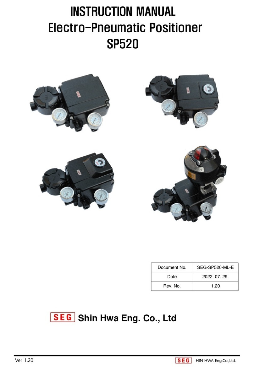
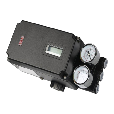
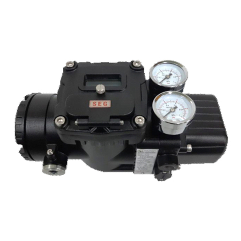
Seg SP520 User manual

INSTRUCTION MANUAL
Electro-Pneumatic Positioner
SP520
Shin Hwa Eng Co., Ltd
Document No.
SEG-SP520-ML-K
Date
2021. 03. 26.
Rev. No.
1.00

Electro-Pneumatic Positioner
SP 520 Series
_________________________________________________________________________________________________________
1
Contents
1. Introduction ····························································································
3
1-1 General Information for users ········································································
3
1-2 Warranty ·································································································
3
1-3 Safety on installation ··················································································
3
1-4 Safety on pipe connection ···········································································
3
1-5 Supply pressure condition ············································································
4
1-6 supply pipe condition ················································································
4
1-7 Safety contents on electrical connection ··························································
4
1-8 Safety to maintain Flame Explosion Proof(SP520) in danger area. ··························
4
1-9 Safety to maintain Intrinsic safety Proof (SP520) in danger area. ····························
5
1-10 Safety Requirements ·················································································
5
2. Products Description ···················································································
6
2-1General Information ····················································································
6
2-2 Main Features and Functions ········································································
6
2-3 Options ···································································································
7
2-4 Label Description ·····················································································
7
2-5 Products Specification ················································································
9
2-6 Explosion Proof Certificate ···········································································
10
2-7 Products Code ··························································································
13
(1) Linear type ···························································································
13
(2) Rotary type ···························································································
14
2-8 Principle of Operation ·················································································
15
2-9 Structure ································································································
17
2-10 Products Dimension ··················································································
18
3. Installation ····························································································
25
3-1Caution before Installation···········································································
25
3-2Tools for Installation·················································································
25
3-3Linear Positioner Installation ·········································································
25
3-3-1 Caution on Installation ··········································································
25
3-3-2 Standard lever type positioner installation steps ··········································
26
3-4 Rotary positioner Installation ········································································
30
3-4-1 Fork Lever type Installation ····································································
30
3-4-2 Namur Type Installation ········································································
30
4. Connection –Air ······················································································
31

Electro-Pneumatic Positioner
SP 520 Series
_________________________________________________________________________________________________________
2
4-1 Supply pressure condition ············································································
31
4-2 Connection-Piping with actuator ··································································
31
4-2-1 Single Acting actuator ··········································································
31
4-2-2 Double acting actuator ·········································································
31
4-3 Air connection per each actuator type ·····························································
33
4-3-1 Rotary Type·······················································································
33
4-3-2 Linear Type ·······················································································
34
5. Connection –Power ·················································································
35
5-1 Safety ···································································································
35
5-2 Cable grand terminal connection for Flame Explosion proof ································
35
5-3 Cable wire for compound recharge type Flame explosion proof································
36
5-4 Terminal connection for non-explosion proof (Non-option) ···································
36
5-5 Terminal connection for non-explosion proof (Feedback option) ·····························
37
5-6 Terminal connection for non-explosion proof (Feedback option + Limit Switch option) ·
38
5-7Terminal connection for Flame explosion proof & Intrinsic Safety -non option·····················
38
5-8Terminal connection for Intrinsic safety proof (Feedback option) ·····························
39
5-9Position transmitter calibration for Intrinsic Safety (Feedback Option) ·······················
39
5-9-1 Mode Setting ·······················································································
39
5-9-2 Calibration Method ···············································································
40
5-10 Terminal connection for Intrinsic safety proof (Feedback + Limit Switch option) ·········
41
5-11Terminal connection concept for Intrinsic Safety Proof type··································
41
5-12Grounding ································································································
42
6. Adjustment ·······························································································
43
6-1SPAN Adjustment and ZERO setting method ······················································
43
6-2Limit Switch Adjustment ···············································································
44
6-3AUTO / MANUAL conversion screw setting method ··············································
44
6-4Orifice setting method ·················································································
45
6-5AUTO / MANUAL conversion screw’s cleaning ····················································
46
7. ERROR Check and solution method ·····························································
46
7-1 Basic check point when positioner does not operate ············································
46
7-2 When positioner does not operate ···································································
47
7-3 Hunting happening in actuator ········································································
47
7-4 When actuator does not control in needing time, but operates ON/OFF only. ···············
47
7-5 When Linearity doses not good ······································································
48
7-6 When Hysteresis does not good ···································································
48

Electro-Pneumatic Positioner
SP 520 Series
_________________________________________________________________________________________________________
3
1. Introduction
1-1 General Information for users
- For the protection and safety of the operator, the product, and the system in which
thisproducts is installed, the safety instructions mentioned in this manual must be
observed.
Safety cannot be guaranteed if the safety instructions in this manual are not properly
followed.
l Installation commissioning and maintenance of the products should be performed by trained
specialist personnel who have been authorized accordingly.
l The manual should be provided to the end-user.
l SP520 Series hardwarecan be upgraded without any prior notice.
l For additional information or if there occur problems that are not stimulated on these manual,
please contact to Shin Hwa Eng. Co.,Ltd. immediately.
1-2 Warranty
l Manufacturer will not take responsible for the personal and physical damage caused by
user's negligence and products modifying or repairing randomly.
If any alternations or modifications are required, please contact to Shin Hwa Eng. Co.,Ltd.
l Quality warranty is valid during the warranty period stimulated in products warranty and shall
be free cost during this period only.
l Even though it is within quality warranty period, following conditions must be paid.
- In case that customer shall maintain or repair products improper randomly.
- In case of happening problems caused by improper movement and storage or dealing
which has exceeded over design condition.
- In case that products shall be used over the specification range.
- In case that problems shall be caused by improper installation.
- In case that it happens on fires, earthquakes, storms, floods, thunder, lightening
other natural disasters, riot, war, radiation exposure, force of majeure situation.
1-3 Safety on Installation
l When installing or replacing positioner equipped with actuator, following safety is required.
- Stop completely valve, actuator and relative surrounding input signal, air pressure.
- Separate by-pass valve or control valve so that overall system may not shut down.
- Make sure that there is no remaining air pressure in actuator.
- In case of enclosures covered with non-conductive material, brush discharge must be
avoided.

Electro-Pneumatic Positioner
SP 520 Series
_________________________________________________________________________________________________________
4
1-4 Safety on pipe connection
l Be care to select facility so that moisture, oil, other materials may not be mixed in pipe of air
compressor and system.
l Prevent to penetrate on moisture,oil and different material with air regulator which is
equipped filter or separated filter device in front of air port on SP520 series.
1-5 Supply pressure condition
l Use drying air with dew point of at least 10°
C
lower than ambient temperature.
l Avoid extra material using filters less than 5 micron. and avoid oil or lubrication oil.
l SP 520 series supply pressure range is 1.4 ~7 kgf/cm2 (140 - 700 kPa).
And do not use over usage range
1-6 Supply pipe condition
l Check that different materials inside pipe must be erased before installing pipe.
l Do not use pipe which is squeezed or damaged.
l Pipeline should have more than 6 mm of inner diameter to maintain SP520 series flow rate.
1-7 Safety contents on electrical connection
l Check that electric power is off before connecting terminal.
SP520 series(except feedback signal internal type) uses 4-20mA DC and in order tooperate
positioner, minimum supplying current is 3.2mA, but maximum supplying current must not
exceed into 24mA.
l In case there is feedback option in SP520 series, separated power must be supplied to feed
back signal and supplying voltage must be 9-28V and not exceed into maximum 30V.
l In order to protect products, positioner internal grounding block should be grounded.
Please do not install the cable near high noise equipments such as high-capacity
transformer or motor.
l Cable or Cable gland should be products which can be used over min. 90°
C
l When equipping cable gland or blanking element, please use explosive proof items which is
over IP66 grade.
1-8 Safety contents to use Flame Explosion Proof SP520 in danger area.
l Check that explosion proof certification is valid in usage condition and must meet with
condition.
l SP520 positioner is using Flame Explosion Proof (Exdbmb(dmb) IIB/IIC T5/T6 Gb, Ex tb IIIC
T80°
C
/T90°
C
Db) code.andIt can be used in Zone 1,2 area.
l In danger area which is exiting explosive gas, explosion proof type of cables or flame
explosion proof packing type cable must be used. In case of using explosive proof cable, it
must be used by gasket and sealed completely.

Electro-Pneumatic Positioner
SP 520 Series
_________________________________________________________________________________________________________
5
l While the power is connected, make sure that do not open SP520 power terminal box.
Before opening terminal box, make sure that power is off completely and after erasing
current and voltage completely, it must be opened.
l SP520 series positioner have 2 ports for power connection. If one side of connection must
be used when using explosive cable or flame explosion proof to packing plug in the other
side should be used explosive blind plug in order to protect.(In case that the other items
shall be required to use except our company's supplying plug blind approved resistance to
explosion proof type structure shielding fitting or flame explosion proof type cable gland
must be used when connecting power on.)
l Ring terminal with surface area of more that 0.195 mm2 with should be used and also M4
spring washer should be used to prevent failing out.
l For external ground terminal, ring terminal with surface area of more than 5.5 mm2 should
be used.
l There will be risk of explosion due to electro-static charge. Static electricity charge may
develop when cleaning the products with a dry cloth. It is imperative to avoid static electricity
charge in the hazard area. If cleaning the surface of the products is required, please use wet
clothes.
1-9 Safety to maintain intrinsic safety (Exi) Proof (SP520) in danger area.
l Check that explosion proof certification is valid in usage condition and must meet with
condition.
l SP520 positioner is using Intrinsic safety proof (EX iaIIB T6 Gb) code.andIt can be used in
Zone 1,2 area.
l Barrier must be installed in safety area.
l SP520 positioner’s intrinsic safety’s parameter is as followings.
Ui=DC28V, Ii=93mA, Pi=0.65W, Ci=0.5nF, Li=10μH
- Do not open the power terminal box cover of the SP520 product while the power is
connected.
- SP520 has two power inlets. When using an explosion-proof cable or pressure-resistant
packing conduit, if only one power inlet is used, the other must be blocked with an
explosion-proof plug.
1-10 Safety Requirements
Caution
Failure to observe the notice may result in damage to the device or may degrade
performance.
Warning
Failure to observe the is caution may result in damage to the device or personal injury.

Electro-Pneumatic Positioner
SP 520 Series
_________________________________________________________________________________________________________
6
Danger
Failure to observe the warning may result in serious injuries or death.
CAUTION
▶Operating the products incorrectly may be degraded the safety.
The well trained person who has proper knowledge and full experience on assembling
and machinery operation should handle this products.
▶Change or modification without permission may be exempt from the manufacturer's
liability.
▶Do not try to handle or disassemble the machine until the safety is firmly secured.
1. Before maintenance or inspection of the machine, make sure that no moving objects
fall or move.
2. Before removing the products, check the safety such as taking safety action and
cutting off the relative electric power and be well aware of the caution of products.
3. When re-operating the machine, make sure that necessary safety action was taken
and operated with safety.
DANGER
▶Please observe the rule relative to safety regulation (National safety regulation)
construction supervision rules and general rules of operation techniques.
▶Please check whether the smart positioner is in proper area or not.
▶Please check whether positioner specification is allowable and range of positioner is
approved in explosion area or not.
▶Please close unnecessary cable bland with approved locking screw in explosive parts
2. Products Description
2-1 General Information
- SP520 Electro-Pneumatic Positioner is a control valve system device that
precisely controls the valve opening by adjusting the pressure supplied to the
valve actuator proportionally by receiving 4-20mA DC input current from the
calibrator, central control room(DCS), and control room. It is a control device.
2-2 Main Features and Functions
(1) With Precise and fast response, it can be available in several type of control valve.
(2) Zero and Span adjustment are easy and convenient.

Electro-Pneumatic Positioner
SP 520 Series
_________________________________________________________________________________________________________
7
(3) For intrinsically safe explosion-proof products, a position transmitter and limit switch can be
built into the positioner.
(4) Explosion-proof products can be externally equipped with position transmitters and limit
switches certified for explosion protection.
(5) It has excellent IP66 enclosure grade.
(6) Air consumption quantity is very small , so in scale plant , the cost can be much saved
(7) Inside structure is Module type and simple to maintain and repair.
2-3 Options
(1) Internal position transmitter (4-20mA DC feedback signal)
(2)External limit switch
(3)External position transmitter
2-4 Label Description
Fig 2-1 : SP520 Sticker name plate
※Caution
Please care not to touch volatile solvent (hardener of instant adhesive, acetone WD-40 etc.
because it can be erased sticker label's print contents.
Fig 2-2 : SP520 Explosion proof nameplate(Ex i)
(KCs, IECEx, ATEX, NEPSI)

Electro-Pneumatic Positioner
SP 520 Series
_________________________________________________________________________________________________________
8
Fig 2-3 : SP520 Explosion proof nameplate(Ex dbmb)
(IECEx, ATEX, NEPSI)
Fig 2-4 : SP520 Explosion proof nameplate(Ex d)
(KCs)
Items of Label
Description
Model No.
Indicate model No according to specification including option.
Ambient Temp.
Indicate ambient temperature valid in explosion proof
certification
Serial No.
Indicate products serial No.
Explosion Proof
Indicate products explosion proof grade.
Input Signal
Indicate the range of input electric signal
Supply Air Press.
Indicate pressure range supplying to positioner.
Enclosure
Indicate enclosure grade of water proof and dust proof.

Electro-Pneumatic Positioner
SP 520 Series
_________________________________________________________________________________________________________
9
2-5 Products Specification
Model
SP520S
SP520D
Acting Type
Single
Double
Motion Type
Linear
Rotary
Linear
Rotary
Input Signal
4~20mA DC
Impedance
240 ± 15 Ω
Air Connection
Rc(PT) 1/4, NPT 1/4
Pres. Gauge Connection
Rc(PT) 1/8, NPT 1/8
Conduit Entry
PF(G)1/2, NPT1/2, M20x1.5
Stroke
10~150 mm
0~90°
10~150 mm
0~90°
Supply Pressure
0.14~0.7 MPa (1.4~7 bar)
Explosion Proof Grade
Ex dbmb(dmb) IIB/IIC T5/T6 Gb
Ex iaIIB T6 Gb
Ex tbIIIC T80°
C
/T90°
C
Db
(IECEx), (
ATEX),
(KCs),
(NEPSI)
Enclosure
IP66
Ambient Temperature
-20~70°
C
(-4°F~158°F)
Linearity
±1% F.S.
±2% F.S.
Hysteresis
±1% F.S.
Sensitivity
±0.2% F.S
±0.5% F.S
Repeatability
±0.5% F.S.
Flow Capacity
70 LPM (Sup.=0.14 MPa)
Air Consumption
2 LPM (sup=0.14MPa), 3 LPM (sup.=0.7MPa)
Humidity
5~95% RH at 40°
C
Feedback Signal (Option)
4~20mA (DC 10~30V )
Material
Aluminum Diecasting
Weight
3 kg (6.6 lb)
Painting
Epoxy Polyestere Powder Coating
Color
Black
• Tested under ambient temperature of 20°
C
,absolute pressure of 760mmHg, and humidity of 65%.

Electro-Pneumatic Positioner
SP 520 Series
_________________________________________________________________________________________________________
10
2-6 Explosion Proof Certificate
▶ KCs
(1) Type :Flame Proof Enclosure
Rating :Ex dmbIIB/IIC T5/T6 Gb
Certification No. :
Ambient Temperature :-20 ~ +70°
C
(T5), -20 ~ +60°
C
(T6)
(2) Type :Intrinsic Safety
Rating :Ex iaIIB T6 Gb
Certification No. :
Ambient Temperature : -20 ~ +70°
C
(3)Type : Dust explosion proof
Rating :Ex tbIIIC T80°
C
/T90°
C
Db
Certification No. :
Ambient Temperature : -20 ~ +70°
C
▶ IECEx
(1) Type : Flame Proof Enclosure
Rating : Ex dbmbIIB/IIC T5/T6 Gb IP66
Certification No.:
Ambient Temperature : -20 ~ +70°
C
(T5), -20 ~ +60°
C
(T6)
(2) Type :Intrinsic Safety
Rating :Ex iaIIB T6 Gb
Certification No.:
Ambient Temperature : -20 ~ +70°
C
(3) Type : Dust explosion proof
Rating :Ex tbIIIC T80°
C
/T90°
C
Db
Certification No.:
Ambient Temperature : -20 ~ +70°
C

Electro-Pneumatic Positioner
SP 520 Series
_________________________________________________________________________________________________________
11
▶ ATEX
(1) Type : Flame Proof Enclosure
Rating :II 2G Ex dmbIIB/IIC T5/T6 Gb IP66
Certification No.:
Ambient Temperature : -20 ~ +70°
C
(T5), -20 ~ +60°
C
(T6)
(2) Type :Intrinsic Safety
Rating :Ex iaIIB T6 Gb
Certification No.:
Ambient Temperature : -20 ~ +70°
C
(3)Type : Dust explosion proof
Rating :II 2D Ex tbIIIC T80°
C
/T90°
C
Db
Certification No.:
Ambient Temperature : -20 ~ +70°
C
▶ NEPSI
(1) Type : Flame Proof Enclosure
Rating : Ex dmbIIB/IIC T5/T6 Gb
Certification No. :
Ambient Temperature : -20 ~ +70°
C
(T5), -20 ~ +60°
C
(T6)
(2) Type :Intrinsic Safety
Rating :Ex iaIIB T6 Gb
Certification No. :
Ambient Temperature : -20 ~ +70°
C
(3) Type : Dust explosion proof
Rating :Ex tbIIIC T80°
C
/T90°
C
Db
Certification No.:
Ambient Temperature : -20 ~ +70°
C
※ Above all certification can be checked in homepage(http://www.seg.co.kr )

Electro-Pneumatic Positioner
SP 520 Series
_________________________________________________________________________________________________________
12
▶Flame Explosion Proof Specification
- IECEx : IEC 60079-0:2017, IEC 60079-1:2014, IEC 60079-31:2013
- ATEX : EN IEC 60079-0:2018, EN 60079-1:2014, EN 60079-31:2014
- KCs : Announcement No. 2020-33 of Ministry of Employment and Labor
▶Intrinsic Safety Explosion Proof Specification
Intrinsic Safety Explosion
Proof Specification
I EC 60079-0:2018
I EC 60079-11:2012
Explosion Proof Class
Ex ia IIB T5/T6 Gb
Barrier Specifications
Ui
Ii
Pi
Ci
Li
Main power
28V
93mA
0.65W
0.5nF
10μH
Feedback signal power
28V
93mA
0.65W
57.5nF
10μH
Limit switch
(Dry contact type)
28V
100mA
0.65W
0nF
0μH
Remark) Please refer to the certificate for further information.

Electro-Pneumatic Positioner
SP 520 Series
_________________________________________________________________________________________________________
13
2-7 Products Code
(1) LINEAR TYPE
MODEL SP520
Acting Type
Single
Double
S
D
Motion
Type
Linear 10~40mm
40~90mm
90~150mm
L1
L2
L3
Feedback
None
Position transmitter (4~20mA DC )
0
1
Explosion
Proof Type
Non explosion type (IP66)
Ex dbmb(dmb) IIB /IIC T5/T6 Gb
Ex ia IIB T6 Gb
Ex tb IIIC T80
°
C /T90
°
C Db
N
D
A
T
Explosion
Proof type
Specification
None(IP66)
KCs
IECEx
ATEX
NEPSI
0
1
2
3
4
Connection
Air – Rc(PT)1/4, Conduit – G(PF)1/2
Air – NPT1/4, Conduit – NPT1/2
Air – NPT1/4, Conduit – M20x1.5
G
N
M
Position
L/S
None
0
Oriffice
None
∅1
∅2
0
1
2

Electro-Pneumatic Positioner
SP 520 Series
_________________________________________________________________________________________________________
14
(2) ROTARY TYPE
MODEL SP520
Acting Type
Single
Double
S
D
Motion
Type
Rotary Fork Lever
Namur
R1
R2
Feedback
None
Position transmitter (4~20mA DC )
0
1
Explosion
Proof Type
Non explosion type (IP66)
Ex dbmb(dmb) IIB /IIC T5/T6 Gb
Ex ia IIB T6 Gb
Ex tb IIIC T80
°
C /T90
°
C Db
N
D
A
T
Explosion
Proof type
Specification
None(IP66)
KCs
IECEx
ATEX
NEPSI
0
1
2
3
4
Connection
Air – Rc(PT)1/4, Conduit – G(PF)1/2
Air – NPT1/4, Conduit – NPT1/2
Air – NPT1/4, Conduit – M20x1.5
G
N
M
Position
L/S
None
2×SPDT
External Type
0
1
2
Oriffice
None
∅1
∅2
0
1
2
※
Optionable items
1. Non -Explosion Proof : Feedback, L/S, Feedback+L /S, External L/S, External (L/S+ Feedback)
2. Ex dbmb(dmb) : External L /S, External (L/S+ Feedback)
3. Ex ia : Feedback, L/S, Feedback+L/S
4. Ex tb: External L/S, External L/S+ Feedback(External equipment can be used by third -party products)

Electro-Pneumatic Positioner
SP 520 Series
_________________________________________________________________________________________________________
2-8 Principle of Operation
(1) LINEAR TYPE
When the input signal (4~20mA) is input, the input current is transmitted to the coil of the
Torque Motor (1) and magnetic force is generated in the core. Move to the left. As a result of
the action, the gap between
pressure in the nozzle pressure chamber (18) drops, resulting in a pressure difference with the
pressure chamber (19).
Accordingly, Spool (9) pushes Poppet A (12) to open port A, and the output
diaphragm valve (3) valve to the top.
In accordance with this movement, the Feedback Lever (20) moves upward and transmits it to
the Output Shaft, and the port A closes and the output of out1 stops and the diaphragm valve (3)
is stopped until the pressure reaches the desired position by repeating the action.
Fig 2-5 : LINEAR TYPE
Pneumatic Positioner
_________________________________________________________________________________________________________
15
Principle of Operation
When the input signal (4~20mA) is input, the input current is transmitted to the coil of the
Torque Motor (1) and magnetic force is generated in the core. Move to the left. As a result of
the action, the gap between the nozzle (17) and the spring support (5) is opened, and the
pressure in the nozzle pressure chamber (18) drops, resulting in a pressure difference with the
Accordingly, Spool (9) pushes Poppet A (12) to open port A, and the output
diaphragm valve (3) valve to the top.
In accordance with this movement, the Feedback Lever (20) moves upward and transmits it to
the Output Shaft, and the port A closes and the output of out1 stops and the diaphragm valve (3)
until the pressure reaches the desired position by repeating the action.
LINEAR TYPE operation principle
_________________________________________________________________________________________________________
When the input signal (4~20mA) is input, the input current is transmitted to the coil of the
Torque Motor (1) and magnetic force is generated in the core. Move to the left. As a result of
the nozzle (17) and the spring support (5) is opened, and the
pressure in the nozzle pressure chamber (18) drops, resulting in a pressure difference with the
Accordingly, Spool (9) pushes Poppet A (12) to open port A, and the output of OUT1 raises the
In accordance with this movement, the Feedback Lever (20) moves upward and transmits it to
the Output Shaft, and the port A closes and the output of out1 stops and the diaphragm valve (3)
until the pressure reaches the desired position by repeating the action.

Electro-Pneumatic Positioner
SP 520 Series
_________________________________________________________________________________________________________
(2) ROTARY TYPE
When the input signal (4~20mA) is input, the input current is transmitted to the coil of the
Torque Motor (1), and magnetic force is generated in the core. With this magnetic force, the
flapper (4) receives the force to the right and the spring support (5) is Move to the left. As a
result of the action, the gap between the nozzle (17) and the spring support (5) is wide
the pressure in the nozzle pressure chamber (18) drops, resulting in a pressure difference with
the pressure chamber (19).
Accordingly, Spool(9) pushes Poppet A(12) to open port A, and the output of OUT1 pushes
Actuator(3) to the right, rotates act
According to this movement, the Span Lever(6) is moved and the spring support(5) is pulled
through the Span lever spring(14), and the gap between the nozzle(17) and the spring
support(5) becomes narrow again,
and stopping the actuator (3) is repeated until the pressure is equalized to reach the desired
position.
Conversely, if the input current is small, the nozzle flapper (9) blocks the nozzle (8) and t
pressure in the nozzle pressure chamber (18) increases, and the spool (9) becomes Poppet B
(8) according to the pressure difference with the pressure chamber (19). Push to open port B
and the output of OUT2 is connected to the actuator(3), and the actua
Fig 2-6 :
Pneumatic Positioner
_________________________________________________________________________________________________________
16
When the input signal (4~20mA) is input, the input current is transmitted to the coil of the
magnetic force is generated in the core. With this magnetic force, the
flapper (4) receives the force to the right and the spring support (5) is Move to the left. As a
result of the action, the gap between the nozzle (17) and the spring support (5) is wide
the pressure in the nozzle pressure chamber (18) drops, resulting in a pressure difference with
the pressure chamber (19).
Accordingly, Spool(9) pushes Poppet A(12) to open port A, and the output of OUT1 pushes
Actuator(3) to the right, rotates actuator stem(21), and is transferred to Cam(20).
According to this movement, the Span Lever(6) is moved and the spring support(5) is pulled
through the Span lever spring(14), and the gap between the nozzle(17) and the spring
support(5) becomes narrow again, and port A is closed and the output of out1 This stopping
and stopping the actuator (3) is repeated until the pressure is equalized to reach the desired
Conversely, if the input current is small, the nozzle flapper (9) blocks the nozzle (8) and t
pressure in the nozzle pressure chamber (18) increases, and the spool (9) becomes Poppet B
(8) according to the pressure difference with the pressure chamber (19). Push to open port B
and the output of OUT2 is connected to the actuator(3), and the actuator stem(21) rotates.
Rotary TYPE operation principle
_________________________________________________________________________________________________________
When the input signal (4~20mA) is input, the input current is transmitted to the coil of the
magnetic force is generated in the core. With this magnetic force, the
flapper (4) receives the force to the right and the spring support (5) is Move to the left. As a
result of the action, the gap between the nozzle (17) and the spring support (5) is widened and
the pressure in the nozzle pressure chamber (18) drops, resulting in a pressure difference with
Accordingly, Spool(9) pushes Poppet A(12) to open port A, and the output of OUT1 pushes
uator stem(21), and is transferred to Cam(20).
According to this movement, the Span Lever(6) is moved and the spring support(5) is pulled
through the Span lever spring(14), and the gap between the nozzle(17) and the spring
and port A is closed and the output of out1 This stopping
and stopping the actuator (3) is repeated until the pressure is equalized to reach the desired
Conversely, if the input current is small, the nozzle flapper (9) blocks the nozzle (8) and the
pressure in the nozzle pressure chamber (18) increases, and the spool (9) becomes Poppet B
(8) according to the pressure difference with the pressure chamber (19). Push to open port B
tor stem(21) rotates.

Electro-Pneumatic Positioner
SP 520 Series
_________________________________________________________________________________________________________
17
2-9 Structure
(1) LINEAR TYPE
(2) ROTARY TYPE
Fig 2-7 : LINEAR TYPE Schematic
Fig 2-8 : ROTARY TYPE Schematic

Electro-Pneumatic Positioner
SP 520 Series
_________________________________________________________________________________________________________
18
2-10 Products Dimension
Fig 2-9 : SP520 LINEAR TYPE (Non Explosive Proof Type)

Electro-Pneumatic Positioner
SP 520 Series
_________________________________________________________________________________________________________
19
Fig 2-10 : SP520 LINEAR TYPE (Explosive Proof Type)
Other manuals for SP520
1
Table of contents
Other Seg Valve Positioner manuals