- 3 -
TECHNICAL DATA MECHANIC
Measurement range [m] 10 / 15
Linearity [%] ±0.05 (depending on the used encoder)
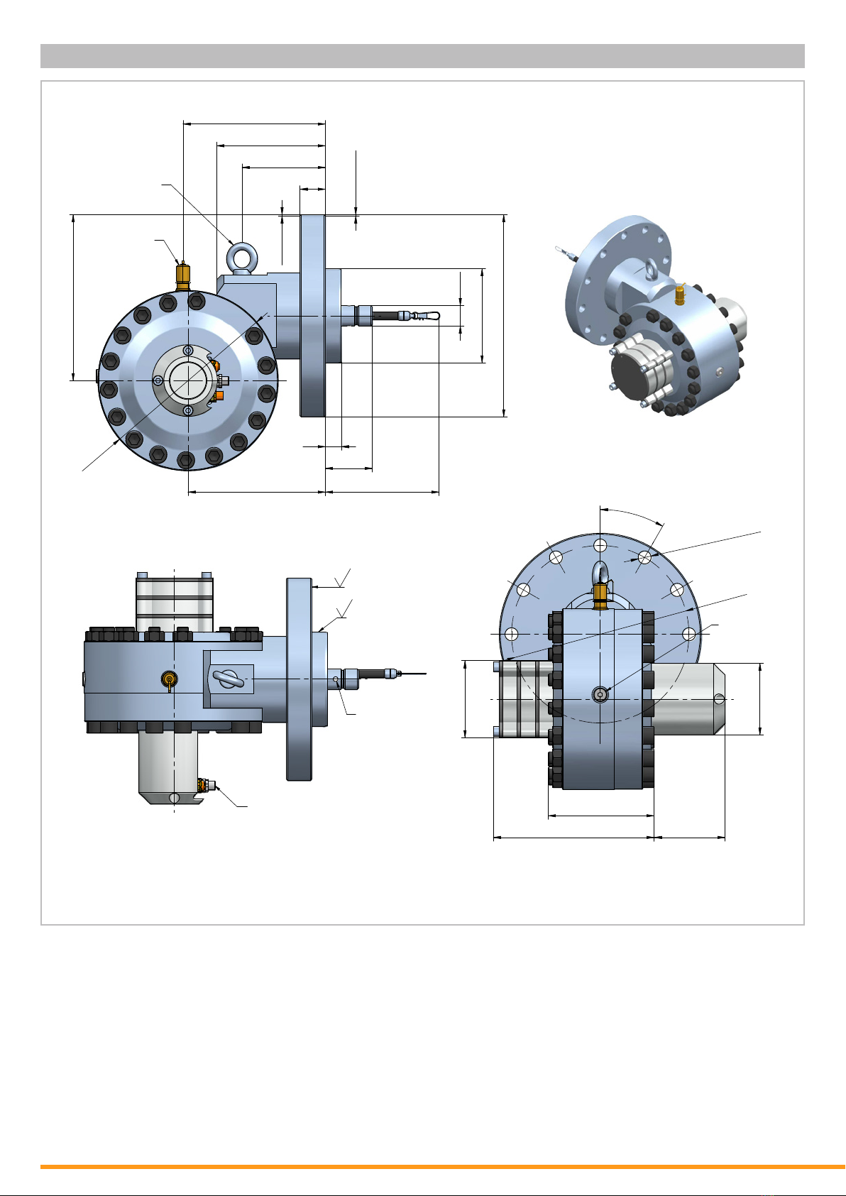
Sheave circumference [mm] 568.9
Operating temperature [°C] -20...+70
Hydraulic uid only non-hazardous uids (non-ammable, non-toxic), no gaseous media
Operating pressure [bar] 300 (30 MPa)
Testing pressure [bar] 400 (40 MPa)
Pressure port Minimess 1620
Piston travel speed [m/s] max. 2 (in air)
Rope tension [N] start of measurement range: 10...11.5 (13...16.5)
end of measurement range: 29...31.5 (37...43)
Wire sag (calculated) [mm] <30
Connector orientation adjustable in 90° steps
Weight [kg] 61
Housing 42CRMo4 (1.7228)
Draw wire stainless steel 1.4301, Ø 0.69 mm
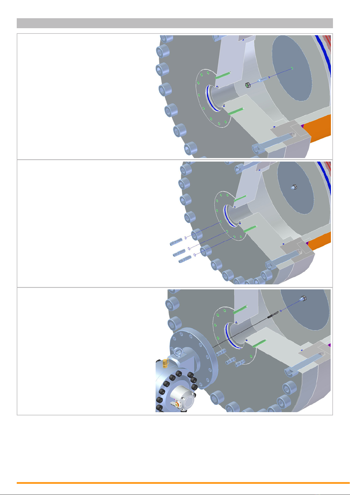
Encoder requirements
[mm]
ange with stator coupling Ø 58
pitch circle diameter for xing screws 63
hollow shaft Ø 15
identified laboratory value without hydraulic fluid
TECHNICAL DATA ENCODER
SSI CANopen Probus-DP EtherCAT Pronet
Linearity [%] ±0.05 (independent of the measurement range))
Resolution scalable (via Software) no yes
Resolution standard [Pulses/mm]
[Bit]
7.2
12
14.4
13
Resolution maximal [Pulses/mm]
[Bit] -115.2
16
Sensor element Multiturn-Absolute-Encoder with optical disc
Connection connector M23,
radial, 12 pins
2 x cable gland,
radial
3 x cable gland,
radial
3 x connector M12, radial, 4 pins
Power supply [VDC] 10...30, reverse polarity protection of the power supply
Current consumption (no load, 24 VDC) [mA] max. 50 max. 100 max. 120 max. 200
Protection class IP65, optional IP67
Humidity max. 90 % relative, no condensation
Temperature [°C] -20...+80
Special cables needed yes