DeZurik P41 User manual

DeZURIK
D10112 © 2012 DeZURIK, Inc.
Instructions
These instructions provide information about Models P41, P41D and P42 PMV Positioners. They are
for use by personnel who are responsible for installation, operation and maintenance of Models P41,
P41D and P42 PMV Positioners
Safety Messages
All safety messages in the instructions are flagged with an exclamation symbol and the word Caution,
Warning or Danger. These messages indicate procedures that must be followed exactly to avoid
equipment damage, personal injury or death. Safety label(s) on the product indicate hazards that can
cause equipment damage, personal injury or death. If a safety label becomes difficult to see or read, or
if a label has been removed, please contact DeZURIK for replacement label(s).
Personnel involved in the installation or maintenance of valves should be constantly alert to
potential emission of pipeline material and take appropriate safety precautions. Always wear
suitable protection when dealing with hazardous pipeline materials. Handle valves that have
been removed from service with the assumption of pipeline material within the valve.
Inspection
Your Model P41, P41D or P42 PMV Positioner has been packaged to provide protection during
shipment; however, it can be damaged in transport. Carefully inspect the unit for damage upon arrival
and file a claim with the carrier if damage is apparent.
Parts
Order parts from your local DeZURIK sales representative, or directly from DeZURIK. When ordering
parts, please include the 7-digit part number and 4-digit revision number (example: 9999999R000)
located on the data plate attached to the valve assembly. Also include the part name, the assembly
drawing number, the balloon number and the quantity stated on the assembly drawing.
DeZURIK Service
DeZURIK service personnel are available to install, maintain and repair all DeZURIK products.
DeZURIK also offers customized training programs and consultation services.
For more information, contact your local DeZURIK sales representative or visit our website at
www.dezurik.com.
DeZURIK
August 2012 Page 3 D10112
Table of Contents
Description - - - - - - - - - - - - - - - - - - - - - - - - - - - - - - - - - - - - - - - - - - - - - - - - - - - - - -
4
Cam Selection - - - - - - - - - - - - - - - - - - - - - - - - - - - - - - - - - - - - - - - - - - - - - - - - - - -
4
Installation - - - - - - - - - - - - - - - - - - - - - - - - - - - - - - - - - - - - - - - - - - - - - - - - - - - - - -
4
Air and Electrical Connections - - - - - - - - - - - - - - - - - - - - - - - - - - - - - - - - - - - - - -
4
Maintenance
Cleaning Positioner Body - - - - - - - - - - - - - - - - - - - - - - - - - - - - - - - - - - - - - - - - - -
5
Cleaning the Restriction Plug - - - - - - - - - - - - - - - - - - - - - - - - - - - - - - - - - - - - - - -
6
Adjustments - - - - - - - - - - - - - - - - - - - - - - - - - - - - - - - - - - - - - - - - - - - - - - - - - - - - -
6
Linkage Rod Adjustment - - - - - - - - - - - - - - - - - - - - - - - - - - - - - - - - - - - - - - - - - -
6
Zero Adjustment - - - - - - - - - - - - - - - - - - - - - - - - - - - - - - - - - - - - - - - - - - - - - - - -
7
Range Adjustment - - - - - - - - - - - - - - - - - - - - - - - - - - - - - - - - - - - - - - - - - - - - - - -
7
Gain Adjustment - - - - - - - - - - - - - - - - - - - - - - - - - - - - - - - - - - - - - - - - - - - - - - - -
8
Reversing Valve Action - - - - - - - - - - - - - - - - - - - - - - - - - - - - - - - - - - - - - - - - - - - - -
9
Trouble Shooting - - - - - - - - - - - - - - - - - - - - - - - - - - - - - - - - - - - - - - - - - - - - - - - - -
10
DeZURIK
D10112 Page 4 August 2012
Description
The Model P41, P41D and P42 PMV Electro-Pneumatic positioner is a precision instrument which,
when used in conjunction with a cylinder actuator, can provide the exacting control necessary to satisfy
the most demanding process requirements. The positioner will accept either a 0–20mA or 4–20mA
input signal.
Cam Selection
Each cam is designed to provide split range instrument signals. Standard cam characterization is linear;
however, other characterizations are available.
Installation
Positioners installed in hazardous areas can be ignition sources. Ensure positioners used in
hazardous areas have proper fire/explosion ratings.
Air and Electrical Connections
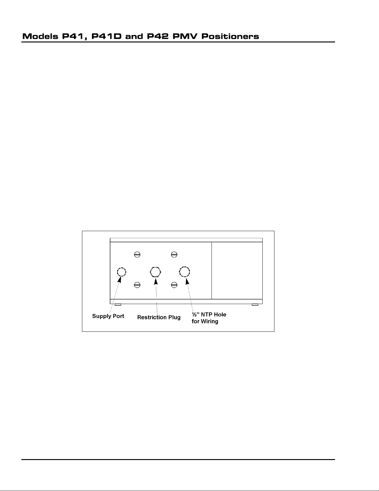
1. Connect instrument quality supply air to the positioner "S" port.
Note: Supply air should be clean, dry and oil-free, with pressure not exceeding the maximum pressure
rating of the cylinder.
2. Remove the top cover and the side frame from the positioner to allow access to the terminal
block.
3. Connect input signal wires to the terminal block inside the positioner.
Note: The positioner case has a 1/2" NPT hole for wiring connector.
4. Actuator piping is connected at the factory to positioner ports C1 and C2. When used on spring-
return actuators, one of the ports is plugged.
DeZURIK
August 2012 Page 5 D10112
Maintenance
Cleaning Positioner Body
To ensure proper positioner operation, it is necessary to periodically clean the positioner valve body
and the restriction plug according to the following steps.
1. Close the valve..
Failure to close the valve may result in the valve slamming shut while the positioner is being
cleaned..
2. Disconnect supply air and instrument signal to the positioner.
3. Remove cylinder tubing from the positioner.
4. Remove the four positioner cover screws and the cover.
5. Remove the side frame from the positioner.
6. Make a note of the position of the indicator, then remove the indicator screw and the indicator.
7. Remove the three screws that hold the valve body to the positioner housing, and carefully lift out
the valve body.
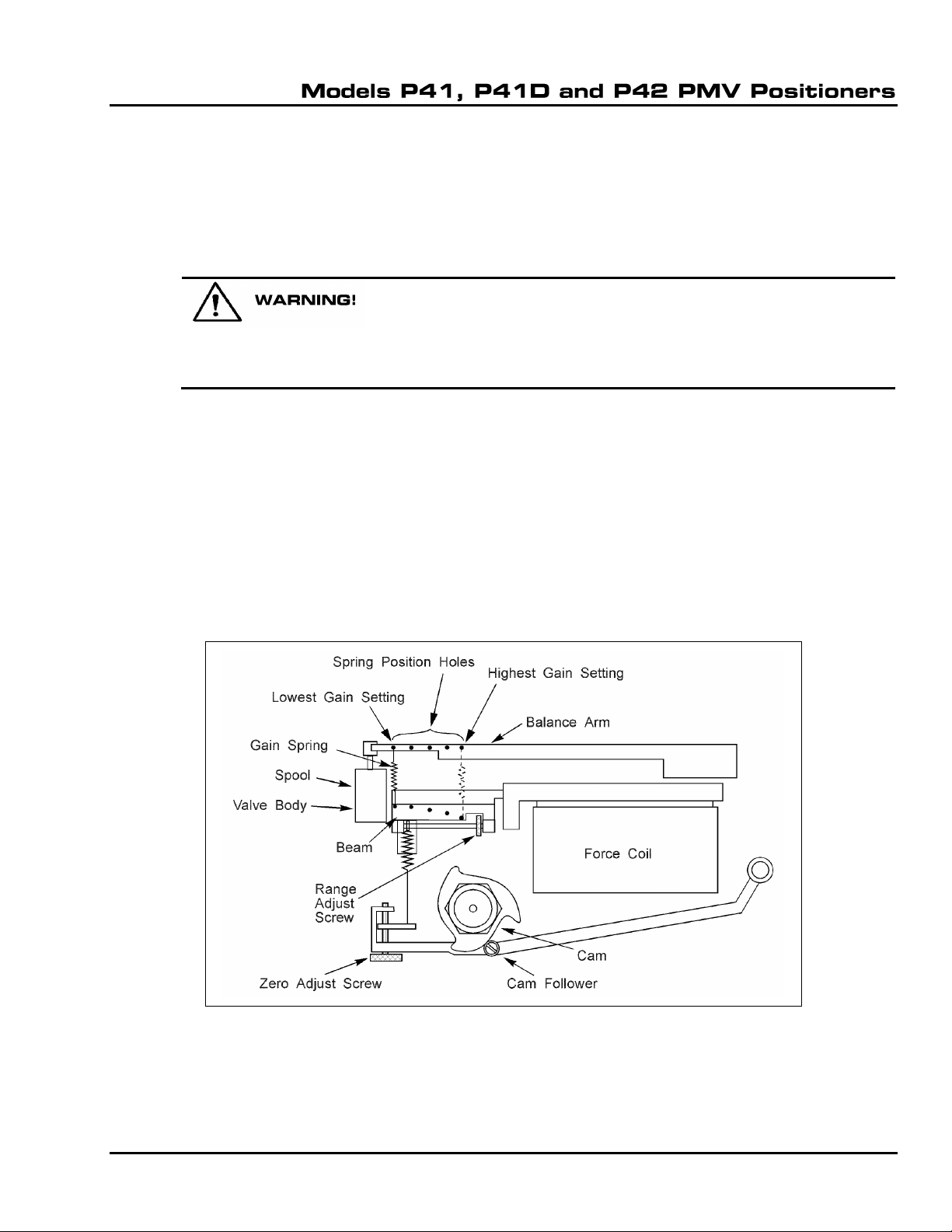
8. Ensure the spool does not bind against the tip of the balance arm. See Figure 1 for parts
location.
Figure 1 –Component Identification
9. Pull the spool out of the body and wash the components.
10. Dry the parts with compressed air, and ensure the ports are clear.
DeZURIK
D10112 Page 6 August 2012
Maintenance (continued)
11. Replace any worn components, then install the spool into the valve body,.
12. Fasten the valve body to the positioner housing and tighten the screws evenly.
13. Place the indicator in the position noted in Step 6, and secure with the screw.
14. Install the side frame and the positioner cover.
15. Connect the tubing from the cylinder to the positioner.
16. Connect supply air and instrument signal to the positioner.
Cleaning the Restriction Plug
1. Remove the restriction plug. (See Figure 2.)
2. Clean the restriction hole (drilled crosswise through the restriction plug) with a fine (0.007inch
diameter) wire.
Note: Do not enlarge the restriction hole.
3. Inspect the O-rings, then install the restriction plug.
4. Install an in-line air filter in the positioner supply port.
Note: Contact the DeZURIK Parts Department to order the filter.
Figure 2 –Restriction Plug Location
Adjustments
These instructions are written for a unit that is piped to Open the valve on an increasing signal. If your
unit is piped to Close the valve on an increasing signal, the valve action will be the opposite of what is
described here.
Linkage Rod Adjustment
If valve position feedback is transmitted through a linkage rod, adjust the length of the rod as follows:
1. Remove the top cover and side frame from the positioner body before adjusting.
2. Set the positioner input signal at the minimum value of its range; for example, 4mA for a 4-
20mA range.

DeZURIK
August 2012 Page 7 D10112
Adjustments (continued)
3. Adjust the length of the rod until the valve is in the position corresponding to the minimum input
signal.
Zero Adjustment
1. Set the positioner input signal at the minimum value of its range, for example, 4mA for a 4-
20mA range.
2. Turn the zero adjust screw clockwise until the valve closes. (See Figure 1 for location of
adjusting screws.)
3. Increase the instrument signal slightly above the minimum range value.
Note: If the valve does not begin to open, turn the zero adjust screw counterclockwise until the valve
just starts to move.
4. Since the zero and range adjustments are interrelated, check the range setting and readjust it, if
necessary.
Range Adjustment
1. Set the positioner input signal at 20mA.
2. Turn the range adjust screw until the valve is in the OPEN position.
3. Decrease the input signal slightly.
4. If the valve does not begin to close, turn the range adjust screw until the valve just starts to
move.
5. Since the zero and range adjustments are interrelated, check the zero setting and readjust it, if
necessary.
DeZURIK
D10112 Page 8 August 2012
Adjustments (continued)
Gain Adjustment
The gain adjustment is preset at the factory to match
your actuator under average conditions. Table A lists
the factory presets.
If it is necessary to adjust the gain,
follow the appropriate procedure:
TO REDUCE GAIN - Move the gain spring away from
the force coil. Ensure the spring is securely hooked in
the beam holes and balance arm notches.
TO INCREASE GAIN - Move the gain spring toward
the force coil. Ensure the spring is securely hooked in
the beam holes and balance arm notches.
Note: After adjusting the gain, you must readjust the zero
and range settings.
Table A: Gain Spring Position
Settings
Actuator
Spring Position
G2C6
Lowest Setting
R1C4
R1C6
R2C6
DR40
G4C8
Second from Lowest
Setting
R2C8
G6C4
Middle Setting
G6C6
G6C8
G12C6
G12C8
G12C10
R3C8
R3C10
DR55/85
DR145/250
Highest Setting
DeZURIK
August 2012 Page 9 D10112
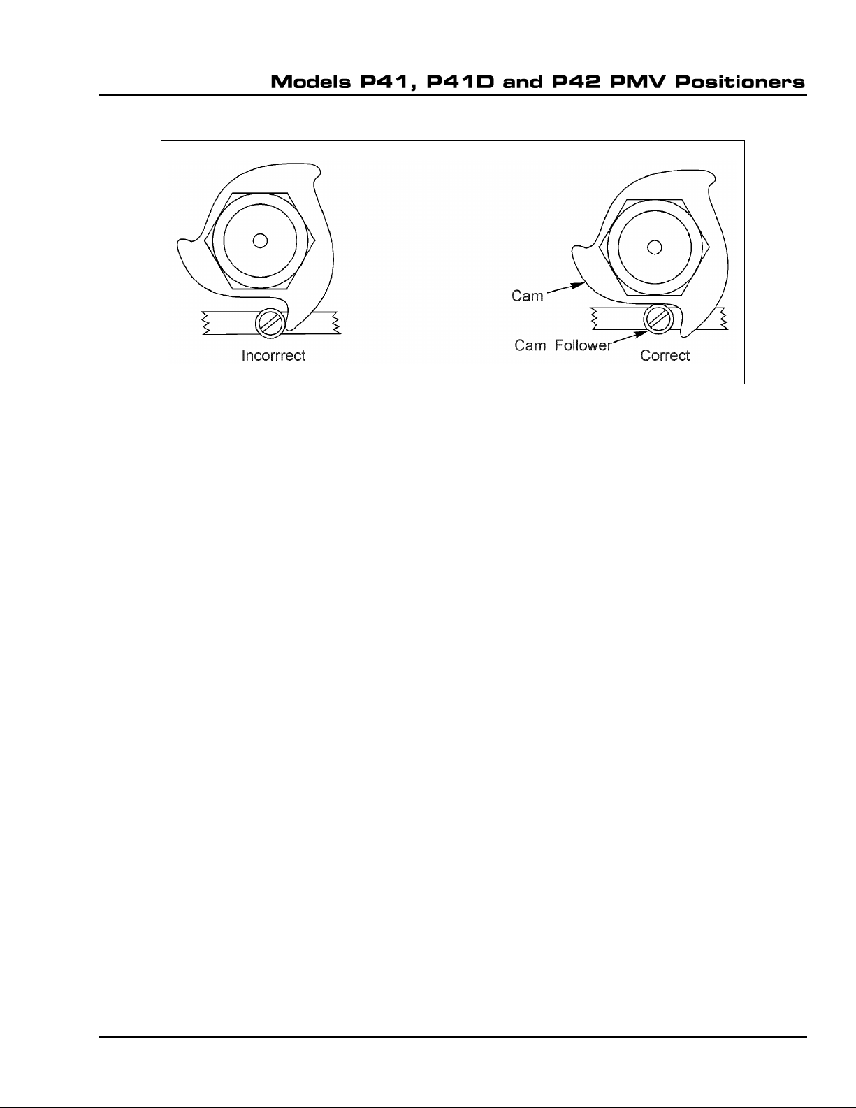
Reversing Valve Action
Figure 3 –Cam Position
To change from having the valve Open, to having it Close, on an increasing signal, follow the steps
below:
1. Close the valve. (Failure to close the valve may result in the valve slamming shut.)
2. Relieve supply air pressure.
3. Reverse the cylinder tubing connections at positioner ports C1 and C2.
4. Remove the four screws that fasten the positioner cover to the positioner, and remove the
cover.
5. Note the position of the indicator, then remove the indicator screw and indicator.
6. Note the cam range being used, then remove the nut and cam.
7. Invert the cam and install it on the input shaft.
Note: Thread the nut loosely.
8. Connect the air supply.
9. Set the positioner input signal at the minimum value of its range, for example, 4mA for a 4–
20mA range.
10. Position the cam as shown in the right side of Figure 3.
Note: Ensure the ball bearing does not ride up on the inactive portion of the cam.
11. Tighten the cam nut.
Note: The cam will turn slightly with the nut as it is tightened. Turn the cam slightly counterclockwise
before tightening the nut, to allow for this.
12. Install the position indicator and the positioner cover.

DeZURIK
D10112 Page 10 August 2012
Troubleshooting
Condition
Possible Cause
Corrective Action
Signal change has no effect on
actuator position
No supply air pressure.
Check for correct air supply.
Signal wires connected wrong.
Check markings on terminal
block.
Broken wire between positioner
terminal block and printed circuit
board.
Check continuity of wiring, and
check for tight connections.
Piping between positioner and
actuator is wrong.
See Assembly Drawing for
correct piping.
Wrong portion of cam being
used.
See Figure 3.
A slight change in input signal
fully actuates valve
Piping between positioner and
actuator is wrong.
See Assembly Drawing for
correct piping.
Inaccurate positioning
Valve body dirty.
See “Maintenance” section.
Restrictor or nozzle dirty.
See “Maintenance” section
Magnet gap has iron dust.
Clean gap.
Supply pressure too low.
Check for correct air supply.
Torque needed to turn valve has
increased.
Look for valve obstructions or
fouling.
Overshoot or hunting during
positioning
Gain setting wrong.
See “Adjustments” section.
Capacity of supply piping too
low, or air filter is plugged.
Check for correct air supply and
clean the filter.

Printed in U.S.A.
Guarantee
Products, auxiliaries and parts thereof of DeZURIK, Inc. manufacture are warranted to the original purchaser for a period of twenty-four (24)
months from date of shipment from factory, against defective workmanship and material, but only if properly installed, operated and serviced
in accordance with DeZURIK, Inc. recommendations. Repair or replacement, at our option, for items of DeZURIK, Inc. manufacture will be
made free of charge, (FOB) our facility with removal, transportation and installation at your cost, if proved to be defective within such time,
and this is your sole remedy with respect to such products. Equipment or parts manufactured by others but furnished by DeZURIK, Inc. will
be repaired or replaced, but only to the extent provided in and honored by the original manufacturers warranty to DeZURIK, Inc., in each
case subject to the limitations contained therein. No claim for transportation, labor or special or consequential damages or any other loss,
cost or damage shall be allowed. You shall be solely responsible for determining suitability for use and in no event shall DeZURIK, Inc. be
liable in this respect. DeZURIK, Inc. does not guarantee resistance to corrosion, erosion, abrasion or other sources of failure, nor does
DeZURIK, Inc. guarantee a minimum length of service. Your failure to give written notice to us of any alleged defect under this warranty
within twenty (20) days of its discovery, or attempts by someone other than DeZURIK, Inc. or its authorized representatives to remedy the
alleged defects therein, or failure to return product or parts for repair or replacement as herein provided, or failure to install and operate said
products and parts according to instructions furnished by DeZURIK, Inc., or misuse, modification, abuse or alteration of such product,
accident, fire, flood or other Act of God, or failure to pay entire contract price when due shall be a waiver by you of all rights under this
warranty.
The foregoing guarantee shall be null and void if, after shipment from our factory, the item is modified in any way or a component of another
manufacturer, such as but not limited to, an actuator is attached to the item by anyone other than DeZURIK, Inc. Factory Service personnel.
All orders accepted shall be deemed accepted subject to this limited warranty, which shall be exclusive of any other or previous Warranty,
and this shall be the only effective guarantee or warranty binding on DeZURIK, Inc., despite anything to the contrary contained in the
purchase order or represented by any agent or employee of DeZURIK, Inc., in writing or otherwise, notwithstanding, including but not limited
to implied warranties.
Metric fasteners should not be used with ASME Class 150/300 bolt holes and flange bolt patterns. If you use metric fasteners with ASME
Class 150/300 bolt holes and flange bolt patterns, it may lead to product failure, injury, and loss of life. DeZURIK Inc. disclaims all liability
associated with the use of metric fasteners with ASME Class 150/300 bolt holes and flange patterns, including but not limited to personal
injury, loss of life, loss of product, production time, equipment, property damage, lost profits, consequential damages of any kind and
environment damage and/or cleanup. Use of metric fasteners with ASME Class 150/300 bolt holes and flange bolt patterns is a misuse that
voids all warranties and contractual assurances. If you use metric fasteners with ASME Class 150/300 bolt holes and flange bolt patterns,
you do so at your sole risk and any liability associated with such use shall not be the responsibility of DeZURIK, Inc. In addition to the
foregoing, DeZURIK’s Manufacturer’s Conditions apply.
THE FOREGOING REPAIR AND REPLACEMENT OBLIGATIONS ARE IN LIEU OF ALL OTHER WARRANTIES, OBLIGATIONS AND
LIABILITIES, INCLUDING ALL WARRANTIES OF FITNESS FOR A PARTICULAR PURPOSE OR OF MERCHANTABILITY OR
OTHERWISE, EXPRESSED OR IMPLIED IN FACT OR BY LAW, AND STATE DEZURIK, INC.’S ENTIRE AND EXCLUSIVE LIABILITY
AND YOUR EXCLUSIVE REMEDY FOR ANY CLAIM IN CONNECTION WITH THE SALE AND FURNISHING OF SERVICES, GOODS
OR PARTS, THEIR DESIGN, SUITABILITY FOR USE, INSTALLATION OR OPERATIONS.
Limitation of liability
LIMITATION OF LIABILITY: IN NO EVENT SHALL DEZURIK, INC. BE LIABLE FOR ANY DIRECT, INDIRECT, SPECIAL OR
CONSEQUENTIAL DAMAGES WHATSOEVER, AND DEZURIK, INC.’S LIABILITY, UNDER NO CIRCUMSTANCES, WILL EXCEED THE
CONTRACT PRICE FOR THE GOODS AND/OR SERVICES FOR WHICH LIABILITY IS CLAIMED. ANY ACTION BY YOU FOR BREACH
OF CONTRACT MUST BE COMMENCED WITHIN 12 MONTHS AFTER THE DATE OF SALE.
Sales and Service
For information about our worldwide locations, approvals, certifications and local representative:
250 Riverside Ave. N., Sartell, MN 56377 ● Phone: 320-259-2000 ● Fax: 320-259-2227
DeZURIK, Inc. reserves the right to incorporate our latest design and material changes without notice or obligation.
Design features, materials of construction and dimensional data, as described in this manual, are provided for your information only
and should not be relied upon unless confirmed in writing by DeZURIK, Inc. Certified drawings are available upon request.
This manual suits for next models
2
Table of contents
Other DeZurik Valve Positioner manuals


Popular Valve Positioner manuals by other brands


rotork
rotork YT-3700 product manual

SMC Networks
SMC Networks IP8000 Installation and maintenance manual

Spirax Sarco
Spirax Sarco CVS10M Installation and maintenance instructions

Flowserve
Flowserve D30 Installation, operation & maintenance manual

STI
STI IMI FasTrak Compact FTC-I instructions

Pepperl+Fuchs
Pepperl+Fuchs Profinet PCV50-F200-B17-V1D manual


