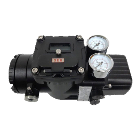
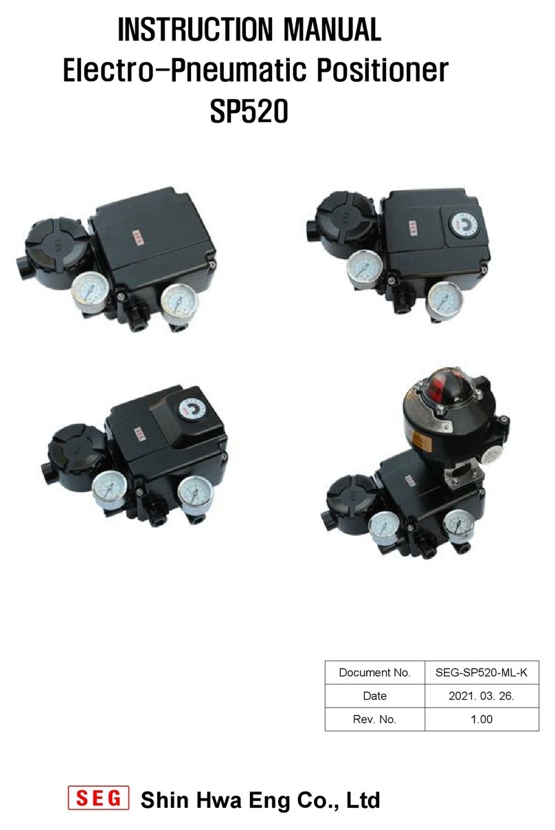
Seg SP740 Series User manual

INSTRUCTION MANUAL
SMART POSITIONER
SP740 Series
1/40
SP-4MIS V1.1
SA-6-10/2019
Shin Hwa Eng Co., Ltd
Software ver. :
Manual ver. :
1/40

Smart Positioner
SP740 Series
TABLE OF CONTENTS
1. Introduction
4
1.1 General Information for users . 4
1.2 Caution on safety 4
1.3 Basic safety instruction for using in the Explosion proof area. 5
1.4 Conditions to maintain the Intrinsic Safety (EXi) 5
1.5 Certification 5
2. Product Description
6
2.1 General Introduction 6
2.2 Features 6
2.3 Options 6
2.4 Label Description 7
2.5 8
2.6 Products Specification 9
2.7 Principle of Operation 10
2.8 Explosion proof specifications of Intrinsic Safety 11
2.9
Structure
12
2.10 13
2.10.1 SP740 Standard Type
13
2.10.2 SP740 Lever Type 14
2.10.3 SP740 Fork Lever Type 15
2.10.4 SP740 Namur Type 16
.---------------------------------------------------------------------------------------
---------------------------------------------------------------
.---------------------------------------------------------------------------------------
Products Dimension
.---------------------------------------------------------------------------------------
.---------------------------------------------------------------------------------------------------------------------------------
.----------------------------------------------------------------------------------------------------
.--------------------------------------------------------------------------------------------
--------------------------------------------------
---------------------------------------------------------------
.---------------------------------------------------------------------------------------
.---------------------------------------------------------------------------------------
.---------------------------------------------------------------------------------------
.---------------------------------------------------------------------------------------
.---------------------------------------------------------------------------------------
Products code
.---------------------------------------------------------------------------------------
.---------------------------------------------------------------------------------------
.---------------------------------------------------------------------------------------
.--------------------------------------------------------------------------------------------
.--------------------------------------------------------------------------------------------
.--------------------------------------------------------------------------------------------
.--------------------------------------------------------------------------------------------
.--------------------------------------------------------------------------------------------
2/40
2.10.4 SP740 Namur Type 16
3. Installation 17
3.1 Causion before installation 17
3.2 Tools for installation 17
3.3 Linear positioner Installation 17
3.3.1 Caution on Installation 17
3.3.2 Standard Lever Type Positioner installation 17
3.4 Rotary positioner Installation 21
3.4.1. Bracket set assembly for Rotary positioner installation 21
3.4.2 Rotary Positioner Installation Step
-------------------------------------------------------------------------------
22
4. Connection - Air 23
4.1 Supply Pressure Condition 23
4.2 Connection - Piping with actuator 23
4.2.1 Single acting actuator 23
4.2.2 Double acting actuator 23
.--------------------------------------------------------------------------------------------
.--------------------------------------------------------------------------------------------
.--------------------------------------------------------------------------------------------
.--------------------------------------------------------------------------------------------
.--------------------------------------------------------------------------------------------
---------------------------------------------------------------
.--------------------------------------------------------------------------------------------
.--------------------------------------------------------------------------------------------
.--------------------------------------------------------------------------------------------
.--------------------------------------------------------------------------------------------
.--------------------------------------------------------------------------------------------
.--------------------------------------------------------------------------------------------
.--------------------------------------------------------------------------------------------
--------------------------------------------------
2/40

Smart Positioner
SP740 Series
5. Connection - Power 24
5.1 Safety 24
5.2 Termainal Connection 24
5.3 Limit Switch Terminal 24
5.4 Instrinsic safety's parts terminal Connection
-------------------------------------------------------------------------------
25
5.5 Ground 25
6. Adjustments 26
6.1
Limit Switch Adjustment
26
7. PCB board Type --Option 27
8. Auto Calibration & PCB Operation 28
8.1 Warning 28
8.2 Button Description 28
8.3 28
8.4 Auto Calibration Mode (AUTO CAL)
------------------------------------------------------------------------------------------
29
8.4.1
------------------------------------------------------------------------------------------
29
8.4.2 Auto All 29
8.5
------------------------------------------------------------------------------------------
30
8.6
------------------------------------------------------------------------------------------
30
8.6.1
------------------------------------------------------------------------------------------
30
8.6.2
------------------------------------------------------------------------------------------
31
8.6.3
------------------------------------------------------------------------------------------
31
8.7
------------------------------------------------------------------------------------------
31
8.7.1 SV NORM 32
.---------------------------------------------------------------------------------------
.---------------------------------------------------------------------------------------
.---------------------------------------------------------------------------------------
Run Mode (RUN )
.---------------------------------------------------------------------------------------
.---------------------------------------------------------------------------------------
.---------------------------------------------------------------------------------------
.---------------------------------------------------------------------------------------
.---------------------------------------------------------------------------------------
.---------------------------------------------------------------------------------------
.---------------------------------------------------------------------------------------
.--------------------------------------------------------------------------------------------
Hand Calibaration Mode (HAND CAL)
Manual Mode ( MANUAL )
Parameter Mode ( PARAMETER )
Dead-Zone ( DEADZONE)
KP_UP ( KP_UP )
KP-DOWN ( KP_DOWN )
Auto PV Calibration AUTO PV )
.---------------------------------------------------------------------------------------
.---------------------------------------------------------------------------------------
.---------------------------------------------------------------------------------------
.---------------------------------------------------------------------------------------
3/40
8.7.1 SV NORM 32
8.7.2 DP NORM 32
8.7.3 FB NORM 32
8.8 Valve Mode (VALVE) 33
8.8.1 Acting Adjustment (ACT DA / RA)
------------------------------------------------------------------------------------------
33
8.8.2 Valve Flow Characterzation Curve (CHAR LN) 33
8.8.3 User Defining Flow Charateristics Adjustment (USER SET)
----------------------------------------------------
34
8.8.4 Tight Shut Open (TSHT OP)
------------------------------------------------------------------------------------------
34
8.8.5 Tight Shut Close (TSHT CL)
------------------------------------------------------------------------------------------
35
36
9. Error and Warning Code
37
9.1 37
9.2 Warning Code 38
10. LCD Operation Map 39
---------------------------------------------------------------
Error Code
.---------------------------------------------------------------------------------------
.---------------------------------------------------------------------------------------
.---------------------------------------------------------------------------------------
.---------------------------------------------------------------------------------------
.---------------------------------------------------------------------------------------
.---------------------------------------------------------------------------------------
.---------------------------------------------------------------------------------------
8.9 View Mode (VIEW)
.--------------------------------------------------------------------------------------------
.---------------------------------------------------------------------------------------
3/40

Smart Positioner
SP740 Series
1. Introduction
1.1 General Information for users
In order to use our products effectively and exactly , please use this products after understanding
this manual completely prior to install and operate.
☞
☞
The manual should be provided to the actual end-user.
☞SP740 Series hardware and software version may be upgraded without prior notice.
☞For additional information or if there occur problems that are not stimulated on this manual,
Please contact to Shinhwa Eng Co., Ltd. Immediately.
1.2 Caution on Safety
This manual contains several observation in order to ensure you personal safety including
prevention from your property damage.
for the safety, please follow the safety guide.
Warning It indicates a situation which, if not avoided, will result in trouble or injury.
of the products.
It indicates a situation which, if not avoided, will result in trouble or low performance
Installation , commissioning and maintenance of this products may be perforemed by trained
specialist personnel who have been authorized by the site operator accordingly.
Caution
The manual describes the cautions required to keep your safety and properties. To classify the level of
severity or urgency of risk, it is divided into 3 levels like 『 Caution 』 『 Warning 』 『 Danger 』
4/40
☞
☞
☞Do not try to handle or disassemble the machine until the safety is firmly secured.
1.
2.
3. When re-operating the machine, make sure that the necessary safety action was taken.
☞This products's case is aluminum material , therefore , it can be happened from
ignition danger when installing , please avoid friction and impact.
☞Please make sure to install so that it may not to affect on outside moisture and protect from
static conditon .
Operating the product incorrectly may lower the safety.
The well trained person who has proper knowledge and full experience on assembling and
machinery operation should handle this products.
Caution
Before maintenance or inspection of the machine, make sure that no moving objects fall or move.
Before removing the product, check the safety such as taking safety measures and cutting off the
relative eletric power and be well aware of the cautions of products.
Warning
It indicates a situation which, if not avoided, will result in trouble or injury.
of the products.
Caution
Changes or modifications without permission may be exempt from the manufacturer's liability.
Danger
It indicate a situation which, if not avoided, will result in death or serious injury.
4/40

Smart Positioner
SP740 Series
1.3 Basic safety instruction for using in explosion proof area
☞ Please observe the rule relative to safety regulation ( National safety regulation )
construction supervision rules and general of operation techniques.
☞ Please check whether the smart positioner is in proper area or not.
☞ Please check whether positioner specification is allowable and range of positioner
is approved in explosion area or not.
☞ Please close unnecessary cable bland with approved locking screw in explosive area.
1.4 Conditions to maintain the Intrinsic Safety (EX i)
☞ In instrinsic safety current only , please connect instrinsic safety protection devices.
To prevent the the risk of explosion , it is necessary to install the product according to the basic safety
instruction to operate in Exi area and national or the regional explosion proof regulations and to prepare
proper safety barrier when organizing the system.
Warning
Danger
5/40
☞ In instrinsic safety current only , please connect instrinsic safety protection devices.
☞ Please observe contents which are stimulated in certificaton and electric data of technical
1.5 Certification
☞IECEx (International Electrotechnical Commission Explosive)
Explosion proof structure : Intrinsic safety
Explosion proof class : Ex ia IIC T5/T6 Ga
Certificate number : IECEx KTL 19.0042X
Ambient temperature : T5 : -30℃ ~ +60℃
T6 : -30℃ ~ +40℃
specification .
5/40

Smart Positioner
SP740 Series
2. Product Description
2.1 General Introduction
Smart Positioner SP740 series are I/P converter type positioner operating kinds of actuators
and valves by converting 4 to 20mA DC signal to pneumatic output proportionally.
The product has acquired IECEx certificate according to "IEC60079-0:2011, IEC60079-11:2011"
standard of IECEx Scheme, and also Intrinsic Safety explosion proof certification (option)
applicable for explosive zone 0.
When applying for an explosive zone, every power supplying to the product should be connected
through a barrier limiting the electrical specification higher than described in the above 2.8.
Besides, installation and wiring etcs relative contents should be observed and worked and used .
2.2 Features
☞It can be applied to various kind of control valve systems
☞Easy and convenient operation
☞Simple maintenance owing that internal parts are modularization .
☞Enclosure IP66
☞Built-in Self diagnostic function
☞Various information about positioner can be processed by HART communication.
☞The function of Auto Calibration is very simple and beginer is available to use .
6/40
2.3 Options
Option function can be added by using simple module operaton only.
☞Position transmitter(4~20mA DC feedback signal)
☞HART communication
☞Limit switch
☞Intrinsic safety explosion proof
6/40

Smart Positioner
SP740 Series
2.4 Label Description
Fig.2-1: SP740 Non-Explosion Proof sticker label Fig. 2-2: SP740 Intrinsic safety explosion
proof sticker label
Input Signal
Indicate the range of input electric signal
Supply Air Press.
Indicate pressure range supplying to positioner
Items of label
Description
Model No.
Indicate model number according to model & specification
Instrinsic safety / Non-
explosion grade
Indicate Instrinstic Safety proof
7/40
Indicates necessary electric data which is composed into
instrinsic saftety wire. Refer to relative cerificate for more details.
Ambient Temp.
Indicate temperature range valid in explsoinon proof certification
Ui, Ii, Pi, Ci, Li
Serial No
Indicate products serial No.
Supply Air Press.
Indicate pressure range supplying to positioner
Enclosure
Indicate enclosure grade of water proof and dust proof. .
7/40

Smart Positioner
SP740 Series
2.5 Products code
SP740 /
S : Single
D : Double
L1 : 20 ~ 80 mm
L2 : 80 ~ 160 mm
R0 : Standard
R1 : Fork lever
R2 : Namur
0 : None
1 : Position transmitter(4~20mA DC)
1 : Fail Safe
* Fail Lock
1 : Non explosion (IP66)
2 :
Intrinsic safety (Ex ia ⅡC T5/T6)
G : Air - PT1/4", Conduit - G(PF)1/2"
N : Air - NPT1/4", Conduit - NPT1/2"
Explosion proof
Connection
Position L/S
Lock condition
Acting type
Lever Type
Linear
Rotary
Output signal
1 2 3 4 5 6 7 8
1
2
3
4
5
6
7
8/40
N : Air - NPT1/4", Conduit - NPT1/2"
0 : None
1 : 2XSPDT
0 : None
1 : HART
Connection
Position L/S
HART
Communication
6
7
8
8/40

Smart Positioner
SP740 Series
2.6 Products Specification
Repeatability ±0.3% F.S.
Linearity
±0.5% F.S.
Hysteresis
±0.5% F.S.
Sensitivity
±0.2% F.S.
Explosion Proof Grade
Ex ia ⅡC T5/T6 Ga
Enclosure
IP66
Ambient Temperature
-30 ~ 85℃
Stroke
10~150 mm
0 ~ 90˚
10~150 mm
0 ~ 90˚
Supply Pressure
0.15~0.7 Mpa (1.5~7 bar)
Air Connection
PT 1/4, NPT 1/4
Pres. Gauge Connection
PT 1/8, NPT 1/8
Conduit Entry
PF(G) 1/2(Standard), NPT1/2(Option)
Input Signal
4 ~ 20mA DC
Minimum Current Signal
2.8mA(Standard), 3.8mA (HART Included)
Impedance
Max. 450Ω @ 20mA DC
Motion type
Linear
Rotary
Linear
Rotary
Model
SP740S
SP740D
Acting Type
Single
Double
9/40
Painting
Epoxy Polyestere Powder Coating
Color
Black
Feedback Signal (Option)
4~20mA (DC 12~28V)
Material
Aluminum Diecasting
Weight
1.8kg
LCD Operating Temp
-30 ~ 85℃ ( -22 ~ 180℉)
Cam Characteristic
Linear(L), Sqare(S), Sqare root(R), User Set (10 Point)
Communication (Option)
HART Communication
Repeatability
±0.3% F.S.
Flow Capacity
70 LPM (Sup = 0.14 Mpa)
Air Consumption
1.8 LTM and lower (sup = 0.14MPa)
Sensitivity
±0.2% F.S.
9/40

Smart Positioner
SP740 Series
2.7 Principle of Operation
Once Control PCB(3) receives an input signal(4~20mA), the input current is delivered to coil(6)
of Torque Motor(1), from which magnetic force is generated in core(7) and the force and polarity
difference with a permanent magnet moves nozzle flapper(9), by which nozzle(8)and nozzle flapper
(9) are far isolated, lowering the pressure of nozzle pressure chamber and finally generating
the difference of pressure with the pressure chamber(14).
Therefore, spool(31) pushes poppet A(12), opening port A; OUT1 output is connected to lower cylinder
(28) while upper cylinder is connected to exhaust pipe, raising piston rod(30). Lever (29) delivers a motion
to Output Shaft(5), operating Pinion(23) and Gear(24) and rotating potentiometer(22), from which
the resistance is fed back to control PCB(3). The feedback value is compared to the input value and
calculated accordingly; if any difference is found, a changed input current is delivered to coil (6)
of Torque motor(1) . so to be properly located while repeating till it is balanced.
On the contraray, if input current is lower, Nozzle Flapper(9) blocks Nozzle(8) so that the pressure
in the nozzle pressure chamber(15) rises, spool(31) pushes poppet B(13)according to the difference
of pressure, opening port B while OUT2 output is connected to upper cylinder(27), and the lower
cylinder(28) is connected to exhaust pipe, lowering piston rod(30). Likewise, lever(29) delivers a motion
to shaft(5), operating pinion(23) and gear(240), rotating position transmitter(22) and finally delivering
the resistance to control PCB(3)
10/40
Fig : 2-3 Principle of operation
11
Display
22
Position transmitter
10
Magnet
21
Pressure Regulator
9
Nozzle Flapper
20
Diaphragm D
31
Spool
8
Nozzle
19
Diaphragm C
30
Piston Rod
7
Core
18
Diaphragm B
29
Lever
6
Torque Coil
17
Diaphragm A
28
Lower cylinder
5
Shaft
16
Adjustment screw
27
Upper cylinder
4
Cylinder
15
Nozzle pressure chamber
26
Limit Cam
3
Control PCB
14
Pressure chamber
25
Limit S/W
2
Pilot Valve
13
Poppet B
24
Gear
1
Torque Motor
12
Poppet A
23
Pinion
입력전류
배기구
10/40

Smart Positioner
SP740 Series
2.8 Explosion proof specifications of Intrinsic Safety
Note : For more details , please note relative certificate
Limit switch
28V
93mA
651mW
0nF
0uH
(Dry contact type)
Feedback signal power
28V
93mA
651mW
3nF
35uH
Main power
28V
93mA
651mW
3nF
35uH
Barrier specifications
Ui
Ii
Pi
Ci
Li
IEC 60079-11:2011
Intrinsic safety explosion proof
grade
Ex ia ⅡC T5/T6
Intrinsic Safety Explosion proof
regulations
IEC 60079-0:2011
11/4011/40

Smart Positioner
SP740 Series
2.9 Structure
12/40
Fig 2-4 Schematic View
SP740 Series Schematic View
①COVER ⑥Potention meter
②PCB Cover ⑦Pilot
③Control PCB ⑧Pilot Valve
④Torque Motor ⑨Base Body
⑤Main Shaft ⑩Cage Block
12/40

Smart Positioner
SP740 Series
2.10 Products Dimension
2.10.1 SP740 Standard Type
13/40
Fig 2-5 : SP740 Standard Type
13/40

Smart Positioner
SP740 Series
2.10.2 SP740 Lever Type
14/40
Fig 2-6 : SP740 Lever Type
14/40

Smart Positioner
SP740 Series
2.10.3 SP740 Fork Lever Type
15/40
Fig 2-7 : SP740 Fork Lever Type
15/40

Smart Positioner
SP740 Series
2.10.4 SP740 Namur Type
16/40
Fig 2-8 : SP740 Namur Type
16/40

Smart Positioner
SP740 Series
3. Installation
3.1 Caution before Installation
☞Maintain proper air pressure and prevent to insert alien substrance and install filter regulator
in Positioner inside air supply line .
☞Supplying air should not be mixed with oil, moisture and impurities.
☞When installing the positioner, make sure to block input signal and air pressure so that it
can be properly operated.
☞Unless it is properly installed, SP740 control condition may be degraded.
3.2 Tools for installation
☞Hex wrench set
☞(+) & (-) Screw drivers
☞Monkey or Spanner
3.3 Linear positioner Installation
3.3.1 Caution on Installation
*When fabricating bracket and connecting lever to actuator , the followings 2 kind of contents
Warning
17/40
*When fabricating bracket and connecting lever to actuator , the followings 2 kind of contents
must be regulated.
*If following condition shall not be regulated during the installation ,
it may be affected the performance of the products linearity function.
☞
When valve opening is 50%, feedback lever should be horizontal.
☞When valve opening is 50% , the connecting bar should be connected into lever angle value
position which is correspondeing to the valve stroke.
Caution
Fig3-1 : Lever installed with vertically when vale stroke is 50%
17/40

Smart Positioner
SP740 Series
3.3.2 Standard Lever Type Positioner installation
① Feedback lever
② Spacer
③ Bracket
④ Bolt(M8)
⑤ Connection bar
SP740 Standard lever type
① Assemble with the enclosed bracket and bolts.
Figure 3-2:
①
②
③
④
⑤
18/40
① Assemble with the enclosed bracket and bolts.
② Connect positioner brackeck with boits in actuator yoke.
Tighten bolts loosely so that they may be modified location easily .
③ Connect air filter regulator in actuator temporarily.
And then decrease slowly into air regulator and valve stroke should be reached into
50% position of overall stroke.
18/40

Smart Positioner
SP740 Series
SP740 (standard lever type)
④ Connection bar located on actuator clamp should be inserted into spring in positioner feed back lever
hole as seen as figure.
Figure 3-3
19/40
hole as seen as figure.
Insert connection bar between lever and lever spring correctly.
⑤ Check whether positioner feed back lever is leveled horizontally in valve stroke 50% position or not.
Unless it is leveled, adjust it horizontally by moving a bracket or positioner body.
Figure 3-4
19/40

Smart Positioner
SP740 Series
ⓐ Check a valve's full stroke.
ⓑ Connection bar should be consisted with feed back lever's value and full stroke value's equal point .
ⓒ If positioner lever and actuator connection bar has not consistent ,
move and adjust positioner bracket or connection bar.
Stroke : 60mm
Fig3-5 Connection bar position when valve stroke is 60mm
20/4020/40
This manual suits for next models
2
Table of contents
Other Seg Valve Positioner manuals
Popular Valve Positioner manuals by other brands

Samson
Samson FOUNDATION 3730-5 Mounting and operating instructions

rotork
rotork YT-2500 Series product manual

Soldo Controls
Soldo Controls IOM-RD00-03 Installation & operation manual

ABB
ABB TZIDC-200 Commissioning instructions

Soldo Controls
Soldo Controls SW Series operating manual

Burkert
Burkert 8791 operating instructions