1 Design and principle of operation
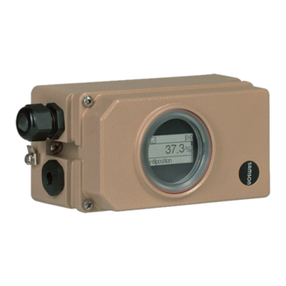
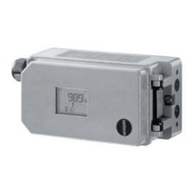
The pne matic positioner is sed to ens re
a preselected assignment between the valve
stem position (controlled variable) and the
control signal (reference variable). In this
process, the o tp t signal from a control de-
vice is compared to the travel of the control
valve and a pne matic signal press re (o t-
p t variable) is s pplied to the act ator.
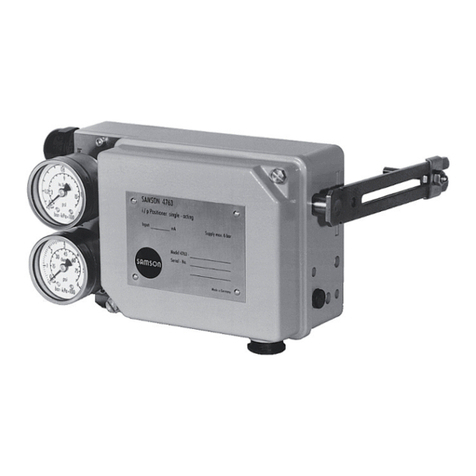
The positioner consists of the lever for travel
pick- p, the meas ring diaphragm, and the
pne matic control system comprising the
nozzle, diaphragm lever (flapper plate),
and the booster.
The positioner is designed either for direct
attachment to SAMSON Type 3277 Act a-
tors or for attachment according to NAMUR
(IEC 60534-6).
The positioner can additionally be eq ipped
with either ind ctive limit switches and/or a
solenoid valve or a position transmitter.
The positioner operates according to the
force-balance principle. The travel, i.e. the
valve position, is transmitted to the pick- p
lever (1) over the pin (1.1), determining the
force of the range spring (4).
This force is compared to the force gener-
ated by the press re pe at the meas ring
diaphragm (5).
If either the control signal or the valve posi-
tion changes, the diaphragm lever (3)
moves, alterating the distance to the
nozzle (2.1 or 2.2) depending on the set
operating direction.
The air is s pplied to the booster (10) and
the press re reg lator (9). The controlled
s pply air flows thro gh the Xp restric-
tion (8) and the nozzle (2.1, 2.2) against
the diaphragm lever (flapper plate).
Any change of the reference variable or the
valve stem position ca se the press re to
change pstream or downstream of the
booster.
The air controlled by the booster (signal
press re pst) flows thro gh the vol me re-
striction (11) to the pne matic act ator,
ca sing the pl g stem to move to a position
corresponding to the reference variable.
The adj stable restrictions Xp (8) and
Q (11) are sed to optimize the positioner
control loop.
The pick- p lever (1) and range spring (4)
m st be selected to match the rated valve
travel and the nominal span of the refer-
ence variable.
Positioner ith inductive limit s itches
In this version, the rotary shaft of the posi-
tioner carries two adj stable tags which ac-
t ate the b ilt-in proximity switches.
Positioner ith solenoid valve
When the positioner is eq ipped with a sole-
noid valve, the control valve can be moved
to its fail-safe position regardless of the posi-
tioners o tp t signal. If a control signal
corresponding to the binary signal "0" (off)
is applied to the inp t, the signal press-
re pst is sh t off and the act ator is vented.
The act ator springs move the control valve
to its fail-safe position.
If a control signal corresponding to the bi-
nary signal "1" (on) is applied to the inp t,
the signal press re pst is s pplied to the ac-
t ator. The control valve is in control oper-
ation.
4EB 8355-1 EN
Design and principle of operation

