Heimeier Thermolux K Owner's manual

Table of Contents
Short instructions 1
Function 2
Important notes 3
– Special features
– Cleaning
– Maintenance & service
– Easier operation for visually handicapped persons
Mounting instructions 4
– Build-in sensor
– Remote sensor
Recommended Room Temperature 6
Temperature setting 7
– Reduced night performance
– Anti-frost protection setting
– Front side setting aid
– Setting aid for visually handicapped persons
Economy clips 8
– Marking of a temperature setting
– Uper marking of a temperature range
– Lower marking of a temperature range
– Limiting of a temperature setting
– Upper limitation of a temperature range
– Lower limitation of a temperature range
– Cancelling the limiting
– Blocking of a temperature setting
– Cancelling of the blocking
Disturbance – Causes – Remedies 10
Thermolux K with remote sensor 12
Accessories 13
Useful comments / Technical data 14
– Appropriate venting
– Cost saving by using external heat
List of headwords 15
1
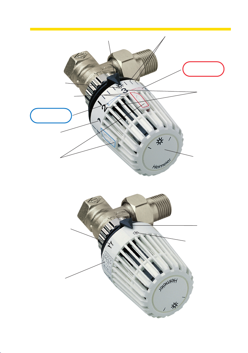
Short Instructions
Temperature difference from
graduation line to graduation
line app. 1 °C
Setting arrow
Reduced night
performance
app. 14 °C
The temperature
difference from
index figure to
index figure
app. 4 °C
Economy clips
(both economy clips are, factory
preset, mounted to the right
and to the left of the short in-
formation) to mark, to limit and
to block a temperature setting
Front side tempe-
rature setting aid
favourable in case
of a bad vision on
the index figures.
Left marking ca.
16°C and right
marking app. 24°C
Basic setting
app. 20 °C
Perceptible marking for
visually handicapped
persons
Sens of rotation
„colder”
Sens of rotation
„warmer”
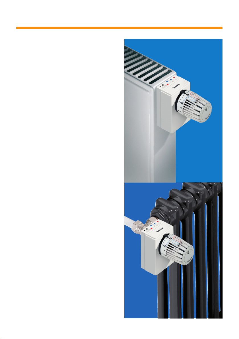
Operation and outfit of the depicted Thermolux K thermostatic valve with incorporated sensor are
identical with those for valves equipped with a remote sensor (please see page 12).
Setting arrow
Anti-frost protection
setting app. 6 °C
Short information
Characteristic sign of the
European Standard
(DIN EN 215)

2
Function
Heimeier Thermolux K thermostatic
valves are autonomously operating
temperature controllers which do not
require any electric power supply or
connection or any other kind of exter-
nal energy. They serve to control the
individual room temperature and,
thus, save energy. The Heimeier ther-
mostatic valves allow different tempe-
rature settings which can be marked
or temperature ranges be limited or
settings be blocked respectively.
Heimeier Thermolux K-thermostatic
valves consist of the thermostatic
head and the thermostatic valve
body . If temperature rises e.g. due
to insolation, electric appliances or
people in the room, the liquid in the
temperature sensor will expand.
The corrugated tube will be com-
pressed and so throttles the water
supply to the radiator by means of the
valve spindle in the valve seat .
Should the room temperature drop
the described procedure will be re-
versed. Therefore, the thermostatic
head only needs actuation in order to
change the individual setting of the
room temperature.
2 1
6
54 3

Dear Customer!
You dispose now of the Thermolux K
thermostatic valve which is a product
of highest quality made by Germany’s
leading manufacturer of heating
valves.
The Heimeier Thermolux K thermosta-
tic valves are CEN certified and were
tested according to DIN EN 215. They
offer you, on the pre-condition of a
correct usage, a maximum of comfort
and energy saving.
This user information intends to make
you acquainted with the operation
and useful application of the ther-
mostatic valves. Even if you know
already well the operation and hand-
ling, you still should read these
instructions carefully and please keep
this booklet in a safe place and pass
it on to any possible later user.
For easier reference and orientation
please consult the coloured sub-
divisons of the table of contents.
Should you look for some specific
item, please refer to page 15 contai-
ning a list of headwords.
The mounting of the thermostatic
valve should exclusively be carried
out by a qualified installer (please see
Mounting Instructions on page 4).
Your installer will help you if you wish
to block an individual temperature
setting or to limit the temperature set-
ting range internally, i.e. unchangeable
from outside, either to a higher or to
a lower temperature level of your ther-
mostatic valves.
Interesting accessories are offered on
page 13.
Special features
This thermostatic head offers several
distinctive features for energy savings
and uncomplicated operation:
– The most important temperature
settings are shown in an abridged
form as INFO on the thermostatic
head
– Economy clips, blue and red
– Reduced night performance
– Temperature setting aid on the front
side
– Anti-frost protection setting
Cleaning
The thermostatic head should only be
cleaned with the upholstery brush of a
vacuum cleaner or in case of heavier
soiling, use lukewarm water containing
a mild domestic cleaning agent.
Maintenance and Service
In principle Heimeier’s thermostatic
valves do not require any maintenan-
ce at all.
In case of questions or possible
disturbances (see pages 10 and 11)
please apply to your installer (see
reverse page of this brochure) or
contact Heimeier directly.
Easier operation for visually handi-
capped persons
With a view to achieving an easier
temperature setting, the thermostatic
head disposes of perceptible mar-
kings for the basic setting (please see
page 7).
Important Notes
3

4
incorrect
The thermostatic head with incorporated
sensor must not be fitted in a vertical
position.
Mounting instructions
Incorporated sensor, remote sensor
The thermostatic valve with incorpora-
ted sensor must not be mounted in
such a way that the valve will be
covered with any curtains, radiator
covers or panelling etc., or be fitted in
narrow alcoves or even be mounted in
vertical position as in such cases no
precise temperature control will be
possible. Otherwise a remote sensor
or remote dial will be indispensable.
correct
The remote sensor can capture the
room temperature without any obstacle.
correct
The air of the room can circulate around the
thermostatic head without any obstacle.
incorrect
The thermostatic head with incorporated
sensor must not be covered with curtains.

5
Note
All Heimeier thermostatic heads are
duly adjusted in a climatic chamber
without any external influences like
heat accumulation, insolation etc.
Depending upon the mounting or
operating conditions, the desired
temperature can, in isolated cases,
only be achieved after having set a
deviating temperature. But this, of
course, has neither any influence on
the regulating accuracy nor on energy
saving. As a rule heating systems are
usually so designed that excessive
temperatures (Index figures 4 and 5)
will not be reached in most cases.
This, the more so, is applicable to
weather-controlled supply temperatu-
res or to the heat generator respec-
tively.
Remote dial
When mounting an underfloor con-
vector (radiator mounted underfloor),
or if the thermostatic head is covered
with furniture or any similar item, a
remote dial should be installed. The
latter captures the room temperature
without any obstacle and offers a
comfortable operation for the purpose
of setting the temperature.
underfloor convector built-in cupboard
5
3 421
INFO
앒6°C
앒14°C
앒20°C
4°C
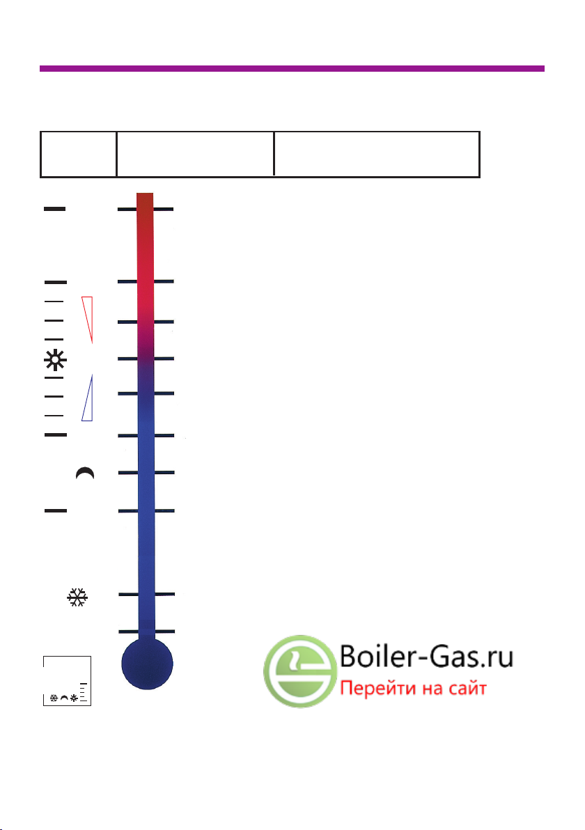
Recommended Room Temperatures
6
The following room temperature settings are recommended for the relevant
rooms in due consideration of energy and cost saving.
Swimming pool *
Bath room
Study and children’s room
Living and dining room
(basic temperature setting)
Hobby, sleeping room
All rooms at night
(reduced heating performance)
Staircase, porch
Cellar rooms
(anti-frost protection setting)
Kitchen, hall
28 °C
24 °C
22 °C
20 °C
18 °C
16 °C
14 °C
12 °C
6 °C **
** Should higher temperatures be required in a swimming pool then special
thermostatic heads are available (set value ranges between 15°C to 35°C).
** Also available are thermostic heads in a version with an additional zero
temperature setting position and, thus, the lowest temperature is 0°C.
Setting Room temperature to be recommended for
position ca. e.g.
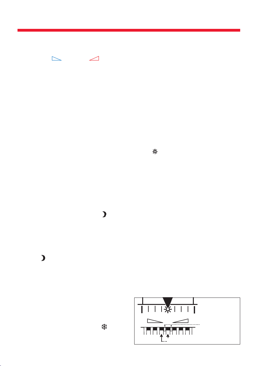
234
from groove to groove about 1° C
two perceptible
markings
7
Temperature Setting
Every desired room temperature can
be set by simply turning the thermo-
static head ( = colder, = war-
mer). In this case, the setting arrow
must point at the relevant setting
position (index figure, graduation line,
symbol). Intermediate adjustments are
possible. The temperature difference
from index figure to index figure is
about 4°C, and from graduation line
to graduation line about 1°C. Recom-
mended by us is a temperature set-
ting of the index figure 3 with the sun
symbol, and this represents the basic
setting of about 20°C. With a view
to saving energy a temperature
setting above index figure 4 should be
avoided, provided that already a lower
temperature setting will be sufficient
for comfortableness. It should espe-
cially be noted that only 1°C of a
lower temperature saves approx. 6%
of the heating cost.
Reduced night performance
In the evening, the thermostatic head
should be turned to the right to reach
the moon symbol, or, when using
the blue economy clip as a limitation,
to this limit stop. Experience proved
that the -setting will be fully suffi-
cient. In the morning the thermostatic
head must simply be turned to the left
in order to reach the desired tempera-
ture setting position or, when the red
economy clip will be used as a limi-
tation, to this limit stop. Even during a
longer absence a temperature re-
duction is advised to be effected.
Anti-frost protection setting
In case of a longer absence in winter,
the anti-frost position warrants that
the temperature in the rooms will not
drop below 6°C, provided, however,
the heating system is in operation and,
thus, the rooms will be protected from
frost damage. This said anti-frost pro-
tection setting can also be chosen for
rooms unused during the winter period.
Front side setting aid
The front side of the thermostatic
head serves as temperature setting
aid in case of bad vision on the cir-
cumferential printing or as setting ori-
entation from a larger distance. The
settings of the markings left and right
to the correspond to 16°C or 24°C
respectively.
Setting aid for visually handicapped
persons
If the thermostatic head is turned
in such a way that the perceptible
markings are opposite to the setting
arrow, a temperature setting of
ca. 20°C will be reached. Starting
from this said basic setting by feeling
and counting the grooves and by
correspondingly turning the ther-
mostatic head to the desired setting
position, the desired temperature
setting position can be reached
whenever the relevant groove will be
opposite to the setting arrow.
The distance between each groove in
the thermostatic head is about 1°C.
3
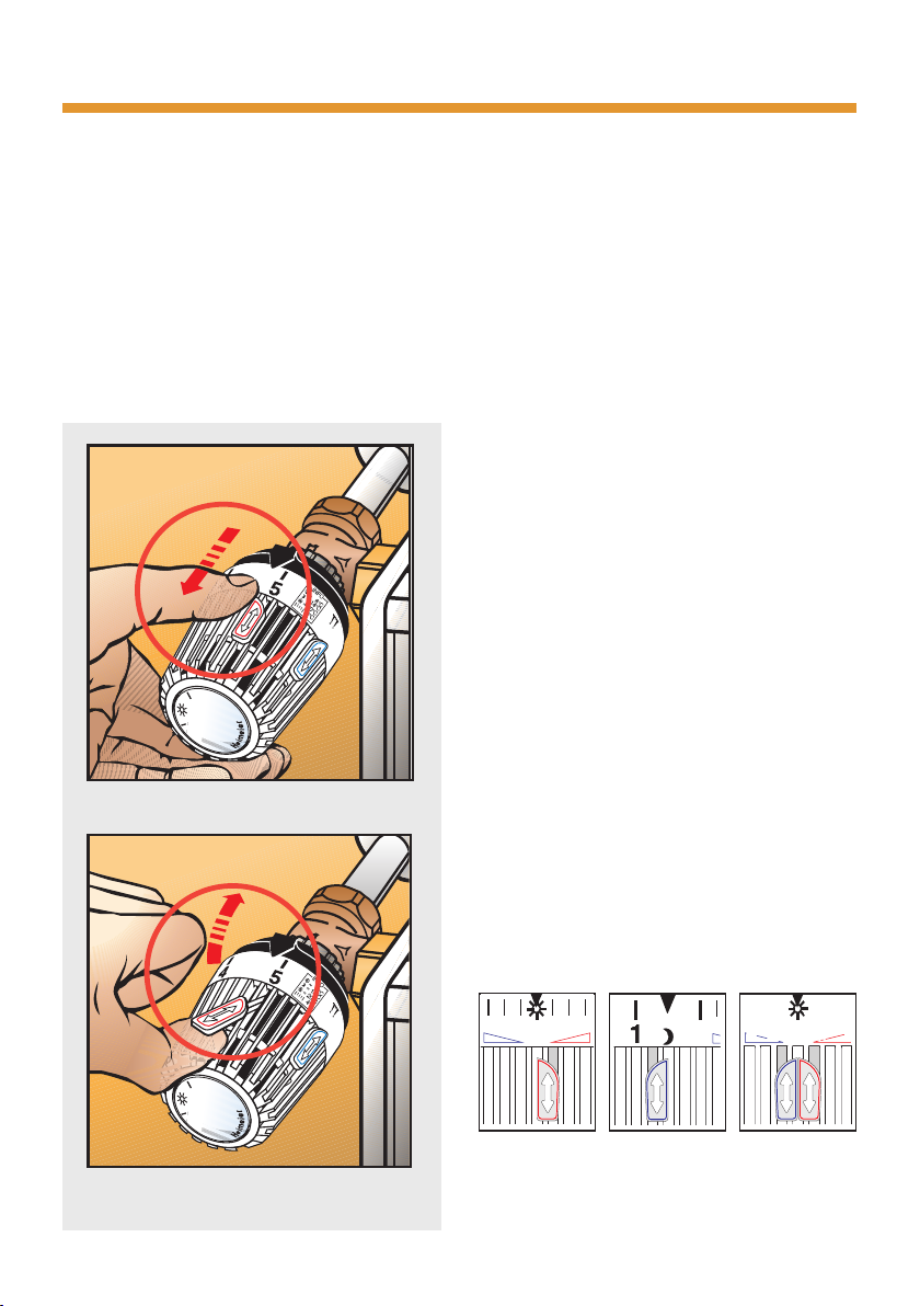
Fig. 3:
red economy
clip for upper
marking/limita-
tion, e.g. 20°C
Fig. 4:
blue economy
clip for lower
marking/limita-
tion, e.g. 14°C
Fig. 5:
blocking,
e.g. 20°C
21
3
8
Economy clips
The thermostatic head will be
supplied, factory preset, with two
economy clips. These economy clips
are at first mounted to the right and to
the left of the short information.
These clips allow a variable
– marking,
– limiting or
– blocking
of an optimal temperature setting.
Marking of a temperature
setting (without limitation)
Upper marking
of the temperature range
For this purpose pull back the red
economy clip with your thumb up to
the stop (please see fig.1), then lift
and remove the economy clip (please
see fig. 2). Thus, the thermostatic
head can be turned and set to the
desired temperature, e.g. index figure
3 = 20°C. Thereafter, the red eco-
nomy clip must be inserted in the
groove to the right of the index figure
3 (please see fig. 3), then push the
clip forward and afterwards pull it
back to the stop with your thumb.
Lower marking
of the temperature range
For this purpose the blue economy
clip must be pulled back up to the
stop with your thumb, then lift and
remove the clip. The thermostatic
head can now be turned to the desi-
red temperature, e.g. moon
symbol = 14°C. Thereafter, the blue
economy clip is to be inserted in the
groove to the left of the moon symbol
(please see fig. 4), push the clip for-
ward and pull it back with your thumb
up to the stop.
Fig. 2: lift and remove the economy clip
Fig. 1: pull back the economy clip

Removing the limitation
For this purpose, the corresponding
economy clip must be pulled back up
to the stop with your thumb. Any
desired temperature setting can now
be made.
Blocking of a
temperature setting
For blocking a temperature setting
both economy clips must be pulled
back (please see fig. 1), the clips must
be lifted and removed (please see
fig. 2).
The thermostatic head must now be
turned to the desired temperature set-
ting, e.g. index-figure 3 = 20°C. Then
the red economy clip is to be inser-
ted in the groove right of the index
figure 3 (please see fig. 5) and be
pushed forward up to the stop. The-
reafter the blue economy clip must
be inserted in the groove left of the
index figure 3 (please see fig.5) and
be pushed up to the stop. The ther-
mostatic head cannot be deregulated
in any direction.
Removing of the blocking.
For this purpose the red and the blue
or, if need be, both economy clips
must be pulled back up to the stop.
Any desired temperature setting will
now be possible again.
Limiting of a Temperature
Setting
Upper limiting
of the temperature range
In this case the red economy clip
must be pulled back up to the stop
(please see fig. 1), lift and remove it
(please see fig. 2). Then the ther-
mostatic head can be turned to the
desired temperature, e.g. index
figure 3 = 20°C. Afterwards the
red economy clip must be inserted in
the groove right to the index figure 3
(please see fig. 3) and the clip pushed
forward up to the stop.
Now every temperature setting up to
the index figure 3 will be possible
when turning the thermostatic head.
Any temperature setting above the
index figure 3 will be impossible.
Lower marking
of the temperature range
For this purpose the blue economy
clip must be pulled back with your
thumb up to the stop, lift and remove
the clip. The thermostatic head can
now be turned and set to the desired
temperature, e.g. moon symbol=14°C.
Thereafter, the blue economy clip
must be inserted left to the moon
symbol (please see fig.4) and the clip
be pushed forward up to the stop.
Now any temperature setting can only
be made up to the moon symbol by
turning the thermostatic head. Tempe-
rature settings which are below the
moon symbol can only be made after
removing the said limitation.
9

10
Disturbances - Causes - Remedies
Radiator does not heat or heats insufficiently only
Possible causes Remedies/comments
– The temperature setting of the – External heat influences lead to an
thermostatic valve is below the increased room temperature. Thus, the
actual room temperature thermostatic valve throttles or even stops
the hot water supply to the radiator
– Air in the radiator – Vent the radiator
– Heating system supplies either – Arrange for checking of heating curve,
insufficient or no heating energy circulation pump, time programme,
at all hot water generator, etc.
The radiator remains heated up even with a closed thermostatic valve
Possible causes Remedies/comments
– In case of a continuous window ven- – Ventilation to be short but intensive
tilation (tilted window position) and low
outside temperatures, the room tem-
perature drops below the lowest tempe-
rature setting on the thermostatic valve
– Valve seat is contaminated or soiled, – Have the foreign body removed.
i.e. the thermostatic head cannot shut off
The thermostatic head cannot be turned or only be moved in a limited manner
Possible causes Remedies/comments
– The thermostatic head was internally – Either the blocking or limiting func-
limited or blocked, e.g. a temperature tions must be cancelled.
setting was blocked or a setting range
was limited towards a higher or lower
level and, therefore, this adjustment
cannot be changed from outside
Any measures in order to remove disturbances in your heating system should either
be judged or be eliminated by a specialist. Please apply to your installer or
approach Heimeier directly (see reverse page of this brochure).

11
Room temperature is distinctly above the set temperature
Possible causes Remedies/comments
– The thermostatic valve does not capture – Take care that the thermostatic valve
the room temperature but is influenced will be exposed to the circulating air
by colder air, e.g. draught of the room without any obstacle
– External heat influences could cause an – Thermostatic valves utilize the external
increase of the room temperature alt- heat supplied free of charge for room
hough the thermostatic valve did shut heating and, thus save energy
off the supply of hot water to the
radiator
Noise in the thermostatic valve
Possible causes Remedies/comments
– Excess differential pressure –
Arrange for reduction of pump pressure or
have the hot water distribution checked
– Air in the heating system – Vent the heating system, refill water
– Wrong flow direction passes through – Arrange for the flow direction to be
the radiator corrected or have a corresponding valve
installed
Room temperature is distinctly below the set temperature
Possible causes Remedies/comments
– The thermostatic valve with incorpo- – Take care that the thermostatic valve
rated sensor is covered with curtains, will be exposed to the circulating air of
radiator covers or panelling etc. the room without any obstacle or have
a remote sensor or remote dial installed
– The thermostatic valve with incorpora- – Arrange for installation of a remote
ted sensor is mounted in vertical position sensor or remote dial
– The nominal performance of the radiator – Have the heating curve or the radiator
is insufficient in relation to the size of the performance adapted
room
– The heating system does not supply – Arrange for checking of heating curve,
sufficient energy circulation pump, time programme,
heat generator, etc.

12
Thermolux K with remote sensor
Remote sensor
Wall
bracket
Capillary tube
Capillary tube coil to roll up the
non required capillary tube
For this product, the main part of the
temperature sensing liquid is situated
in the remote sensor, contrary to the
Thermolux K with built-in-sensor, and
actuates from there via the capillary
tube the corrugated tube in the ther-
mostatic head.
But otherwise the functional principle
is equal to the Thermolux K ther-
mostatic valve with built-in sensor
(please see page 2). Even the ope-
ration and the outfit are identical
(please see page 1).
13
Accessories
With E-Pro achieving substantial
energy savings is child’s play.
E-Pro enables an automatic reduction
of roomtemperature up to 4 °C,
without time-consuming programming
– and can be done by anyone at any
time.
Perfect for rooms that are only used
at times or in different ways, such as
bathroom, kitchen, living room or
bedroom.
In principle E-Pro has two buttons
which are used to carry out individual
time programming practically in pas-
sing. In this case a simple push of the
button replaces the typical situation of
turning the thermostatic valve down
or up.
E-Pro is the modern partner of the
HEIMEIER thermostatic valve –
regardless whether it is already on
hand or for a new installation. Energy
savings of up to 20 percent – this
cannot be done any more easily or
inexpensively!
For further information regarding
E-Pro please approach Heimeier
directly – or contact your installer
(see reverse page of this brochure).

14
Useful comments
Correct venting
Venting should not be used to control
the room temperature but only to
exchange stagnant air for oxygen-rich
air. Venting should be short but inten-
sive, i.e. windows should be fully
opened for a short time. But during
such venting the thermostatic head
should be turned back to the anti-
frost protection position.
After venting the previous temperature
setting can easily be found again
when using the economy clips (mar-
king, limitation).
Saving by using cost-free
external heat
Such external heat sources are e.g.
lamps, insolation, electric appliances,
people staying in the room etc.
This external heat has an influence on
the room temperature and, in turn, on
the thermostatic valve (please see
page 2).
Should the so generated heat in the
room lead to a higher room tempera-
ture than the temperature setting on
the thermostatic head, the thermosta-
tic valve will shut off the hot water
supply to the radiator and the radiator
will cool off.
Technical Data
Heimeier Requirements acc. to
Thermolux K European standard DIN
EN 215
Setting range from 6 °C up to 28 °C
Anti-frost protection at 6 °C
Max. sensor temperature 50 °C
Hysteresis 0,2 K max. 1 K
Differential pressure influence 0,3 K max. 1 K
Water temperature influence < 0,4 K max. 1,5 K
(built-in sensor)
Water temperature influence < 0,3 K max. 0,75 K
(remote sensor)
Notes:

15
List of Headwords
Keywords Page
Alcoves 4
Accessories 13
Anti-frost protection 3, 6, 7
Basement 6
Basic setting 1, 7
Bath room 6
Bed room 6
Blocking 9
Capillary tube 12
Cellar 6
Childrens room 6
Cleaning 3
Comfortableness 7
Corrugated tube 2
Curtain(s) 4
Dining room 6
Disturbance(s) 10
Economy clip(s) 1, 3, 8, 9
Excess temperature 5
External heat source 14
Function 2
Furniture (outfit) 5
Graduation line 1, 7
Hall 6
Heat accumulation 5
Heat generator 10, 11
Heating cost 4
Heating curve 10, 11
Hobby room 6
Important notes 3
Index figure(s) 7
Insolation 5
Intermediate adjustment(s) 7
Kitchen 6
Limitation 9
Living room 6
Maintenance 3
Marking 8
Moon symbol 6, 7
Mounting instructions 4, 5
Night performance, reduced 3, 6, 7
Noises 11
Office 6
Panelling 13
Porch 6
Pump 10, 11
Radiator cover 4
Radiator panelling 4
Reduced performance 3, 6, 7
Regulating 6, 7
Remote dial 4, 5
Remote controller 4, 5
Remote sensor 4, 12
Room temperature 2, 6, 7, 14
Sens of rotation 1
Sensor 2, 4
Service 3
Setting aid 7
Setting arrow 1, 7
Short information 1
Short instructions 3, 6
Sleeping room 6
Special features 3
Stair-case 6
Study 6
Sun symbol 7
Swimming pool 6
Technical data 14
Temperature controller 2
Temperature sensor 2
Temperature setting(s) 6
Thermostatic head 2
Thermostatic valve body 2
Underfloor convector 5
Useful comments 14
Valve seat 2
Valve spindle 2
Venting 14
Visually handicapped person(s) 1, 3, 7
Zero°C position 6
Time programming 13
Keywords Page

Table of contents
Popular Valve Positioner manuals by other brands


halstrup-walcher
halstrup-walcher PS-3 Series Original instruction manual

Trimteck
Trimteck Optimux HPP5500 Series product manual

Siemens
Siemens SIPART PS2 FF Compact operating instructions

Ros
Ros PT-25FB-24VDC-RS-485 Operating and maintenance manual

Micronix
Micronix PPS-28 series Reference manual

KAUP
KAUP 3T450A operating manual


