1 Design and principle of
operation
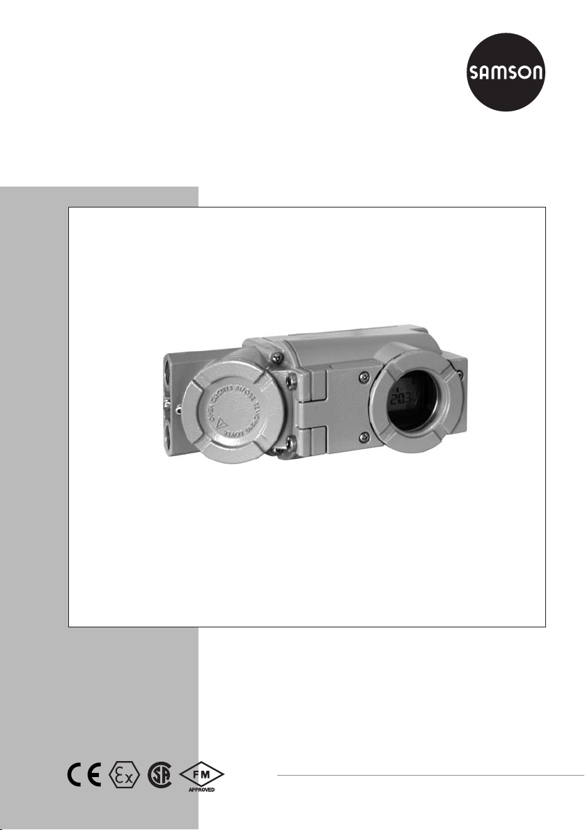
The electropneumatic Ex d positioner is
mounted to pneumatic control valves and is
used to assign the valve position (controlled
variable x) to the control signal (reference
variable w). The DC control signal received
from a control unit is compared to the travel
or rotational angle of the control valve and
the corresponding signal pressure (output
variable y) is issued.
The positioner is designed depending on the
corresponding accessories for direct attach-
ment to Type 3277 Actuators or for attach-
ment to actuators according to IEC 60534-6
(NAMUR).
Additionally, a coupling wheel included in
the accessories is required to transfer the ro-
tary motion for rotary actuators according to
VDI/VDE 3845.
Springless rotary actuators require a revers-
ing amplifier included in the accessories to
permit the powered operation in either di-
rection.
The positioner basically consists of a travel
sensor system that functions proportional to
resistance, an analog i/p module with
downstream booster as well as the electronic
unit with a microcontroller. All parts are en-
closed in an Ex d housing. The electrical
cables are connected over a separate termi-
nal compartment which also has Ex d pro-
tection.
The position of the valve is transmitted as
linear travel motion or angle of rotation to
the travel sensor (2) and to an analog PD
controller (3). Simultaneously, an A/D con-
verter (4) transmits the position of the valve
to the microcontroller (5). The PD controller
compares the actual value with the 4 to
20 mA DC control signal issued by the con-
trol unit.
In case of a system deviation, the operation
of the i/p converter (6) is changed so that
the actuator (1) is filled or vented via the
downstream air capacity booster (7). This
causes the closure member of the control
valve to move to the position determined by
the reference variable.
The pneumatic air capacity booster (7) and
the pressure regulator (8) are provided with
supply air. An intermediate flow regulator
(9) with fixed settings is used to purge the
positioner and also guarantees trouble-free
operation of the pneumatic booster. The out-
put signal pressure supplied by the booster
can be limited over the software.
Serial interface
The positioner is equipped with an interface
to allow the SAMSON TROVIS-VIEW Con-
figuration and Operator Interface software
to transmit data and parameters over a se-
rial interface adapter from the RS-232 inter-
face of a computer to the positioner.
Options
Forced venting: If there is no operating volt-
age at the corresponding terminals, the i/p
module is not actuated. The positioner
cannot operate anymore and the control
valve moves to the fail-safe position deter-
mined by the actuator, independent of the
reference variable.
Binary contact: The positioner has three in-
ternal binary signals which can be analyzed
over the A/B/C terminals. Two of these sig-
nals are assigned to the valve end positions
6EB 8387-3 EN
Design and principle of operation