Segway NINEBOT ONE S1 User manual
Service Manual


Service Manual 3
Trademark, Patent, and Contact Information
Document number and revision: 25399-00001 ab
Copyright © 2017 Segway. All rights reserved.
Trademarks
Segway® is the registered trademark of Segway Inc. Ninebot™ and the shape icon are registered trademarks
of Ninebot (Tianjin) Technology Co., Ltd.; ARM®, that of ARM company; iPhone, iOS, that of Apple Inc. Android,
that of Google Inc. The owners reserve all the rights of their trademarks referred to in this manual, and Ninebot
reserves all the rights of Ninebot™ and the shape icon.
Patents
Ninebot holds various patents relating to Ninebot products, with other patents pending. This manual is
prepared by Segway, who reserves all its copyrights. No institute or individual shall copy or disseminate this
manual in whole or in part, or make use of the aforesaid patents without the prior written consent of Ninebot or
Segway.
The One S1 is covered by U.S. and foreign patents.
For patent information go to www.segway.com.
Ninebot (Tianjin) Technology Co. Ltd. manufactures and sells the One S1 under a license from DEKA Products
Limited Partnership.
Contact Information
Website: www.segway.com
E-mail: technicalsupport@segway.com
Technical Support: 1-866-473-4929, prompt #2

4One S1
Contents
Trademark, Patent, and Contact Information.............................................................................3
Safety ............................................................................................................................7
Introduction..................................................................................................................9
Hardware
Batteries..................................................................................................................... 13
Battery Cover...............................................................................................................................14
Battery ..........................................................................................................................................15
Battery Test...................................................................................................................................16
Pedals......................................................................................................................... 17
Pedals ...........................................................................................................................................18
Pedal Components .....................................................................................................................19
LED Strips .................................................................................................................. 21
LED Covers ..................................................................................................................................22
LED Strips.....................................................................................................................................23
Body ........................................................................................................................... 27
Body Disassembly.......................................................................................................................28
Body Assembly............................................................................................................................32
Frame ......................................................................................................................... 37
Control Board Assembly ............................................................................................................38
Control Board Components ......................................................................................................40
Front/Rear Frames.......................................................................................................................42
Handle ..........................................................................................................................................43
ON/OFF Button...........................................................................................................................44
ON/OFF Board............................................................................................................................45
Charge Port..................................................................................................................................46
Charge Port Cover ......................................................................................................................47
Buzzer ...........................................................................................................................................48
Temperature Sensor ...................................................................................................................49

Service Manual 5
Wheel and Tire.......................................................................................................... 51
Hub Brackets................................................................................................................................52
Tire/Inner Tube ............................................................................................................................53
Software
Ninebot App ............................................................................................................. 57
Ninebot App Installation ............................................................................................................58
Connecting to a One S1.............................................................................................................59
Ninebot App Overview ..............................................................................................................60
Black Box......................................................................................................................................61
Battery Information .....................................................................................................................62
Updating the Firmware ..............................................................................................................63
Resetting the Serial Number .....................................................................................................64
Calibrating the Balance Sensor.................................................................................................65
Resetting the Bluetooth Password ............................................................................................66
Appendices
Post-Service Tests ..................................................................................................... 69
Tools and Equipment............................................................................................... 71
Contents

6One S1
Contents
7
Safety
Service Manual
Safety
Safety Conventions
The following safety messaging conventions are used throughout this document:
WARNING! Warns you about actions that could result in death or serious injury.
CAUTION! Warns you about actions that could result in minor or moderate injury.
NOTE
Indicates information considered important, but not related to personal injury.
Examples include messages regarding possible damage to the One S1 or
other property, or usage tips.
Important Safety Notices
Read and follow all safety notices.
WARNING!
• To replace parts on the One S1, you must read and follow all instructions and warnings in this manual.
• If servicing a One S1 on a raised surface such as a table, be sure to secure the One S1 so it cannot fall.
• Always power off the One S1 before performing any maintenance or installing any part or accessory.
Always unplug the power cord before performing any maintenance or installing any part or accessory.
• Do not use the battery if the case is broken or if the battery emits an unusual odor, smoke, or excessive
heat, or leaks any substance. Avoid contact with any substance seeping from the battery. Batteries contain
toxic and corrosive materials that could cause serious injury. If you experience any of the above, call
Segway Technical Support immediately at 1-866-473-4929, prompt #2.
• Observe and follow all safety information on the warning label found on the battery and all other labels.
• Use only charging devices approved by Ninebot or Segway and never attempt to bypass or override their
charging protection circuits.
• Do not wash the One S1 with a power washer or high pressure hose. Avoid exposure to heavy downpours
or extended periods of heavy rain (including during riding, storage, or while being transported). Clean with
soap and water and a soft cloth. Make sure that the charge port is dry before you plug in the power cord.
• Do not submerge the One S1 or battery in water. If you suspect the battery has been submerged or
experienced water intrusion, call Segway Technical Support immediately at 1-866-473-4929, prompt #2.
Until you receive further instructions, store the One S1 outdoors and away from ammable objects.
• As with all rechargeable batteries, do not charge near ammable materials. When charging, the batteries
heat up and could ignite a re.
• Always wear gloves when handling chemicals (such as lubricants, corrosion inhibitors, greases, or oils) to
reduce the potential for skin damage or irritation.
• When a procedure requires the use of safety glasses (such as those in which a mallet or solvent is used),
failure to wear eye protection could result in serious injury.
• Failure to adhere to these warnings could lead to serious injury, death, re, or damage to property.
CAUTION!
• When a repair involves removing, disconnecting, or handling electronic components, use best-practice
electrostatic discharge (ESD) control procedures to avoid damaging sensitive electronic components.

Safety
8One S1

9
Introduction
Service Manual
Introduction
Purpose
The purpose of this manual is to provide instructions for servicing the
Ninebot One S1 by Segway.
Audience
This manual is written for authorized service technicians.
General Service Procedures
Before performing any service on the One S1, you must rst determine
which components may be damaged or malfunctioning. In some cases
this requires a simple visual inspection — as in the case of a cracked or
damaged housing. In other cases diagnostic equipment must be used
to troubleshoot the problem — as in the case of a vehicle limiting the
maximum speed to lower than expected.
No matter what the problem is, the service procedure is the same:
1. Identify — identify the symptoms.
2. Diagnose — determine which components may be malfunctioning.
3. Replace — replace the malfunctioning component(s).
4. Verify — operate the vehicle to verify the problem has been solved.
It may be the case that there are multiple problems affecting a One S1.
Try to isolate the problems and solve them one at a time.
Related User Materials
This document is a service manual intended for use by trained
technicians to service and repair the One S1. It does not contain
general operating information. The following additional user materials
may be needed for reference during service:
• Ninebot One S1 by Segway User Manual
Please check www.segway.com for the latest user manual, and/or
contact Segway to conrm you have on hand the most recent service
publications.
Unit Orientation
When servicing the One S1, unit orientation is referenced as shown in
the illustration to the right
Charging Port
(rear)
ON/OFF Button (front)
Left Right

Introduction
10 One S1
Control Board Connectors
Some One S1 connectors have a locking tab holding it in place. To
unplug/disconnect these connectors you must depress the locking tab
while pulling on the connector.
NOTE
When pulling on a connector it is possible to pull the socket as well. Be
careful not to pull the socket off the board.
Fasteners
Always tighten fasteners in a cross pattern to ensure that components
sit at against each other. Tighten fasteners to the torque specication
listed (if provided). If no torque specication is provided, tighten
fasteners securely, but do not overtighten.
NOTE
If a fastener falls into the housing/interior of the unit during service,
you MUST remove the fastener before turning ON or operating the
unit. A loose fastener could possibly cause a short or some other type
of mechanical failure.
ESD Protection
When a repair involves removing, disconnecting, or handling electronic
components, use best-practice electrostatic discharge (ESD) control
procedures to avoid damaging sensitive electronic components.
At a minimum, ESD protection should include an antistatic mat and an
antistatic wrist strap. Both these items must be properly grounded.
Power Tools
Do not use power tools when servicing the One S1. Tighten fasteners
to the torque specication listed (if provided). If no torque specication
is provided, tighten fasteners securely, but do not overtighten.

Hardware
Installation and Removal Procedures

12 One S1

13
Batteries
Service Manual
Overview
There are two batteries, one on each side of the unit. Each battery
is accessed by opening the battery cover. A gasket underneath the
battery cover protects the batteries from the elements.
This component is not serviceable; if there is a problem with the
battery it must be replaced.
When to Replace
Replace when troubleshooting determines that the battery is
malfunctioning.
Safety
WARNING!
Always remove the batteries before servicing the One S1. Failure
to remove the battery could result in serious injury or death due to
electric shock.
WARNING!
After removing the batteries, press the ON/OFF button to discharge
any residual energy in the One S1. Failure to do so could result in
serious bodily injury from electric shock.
WARNING!
Do not allow any metallic object to touch the pins of the battery
connector. Shorting these pins could result in a hazardous release of
stored energy.
WARNING!
Do not use the battery if the case is broken or if the battery emits
an unusual odor, smoke, or excessive heat, or leaks any substance.
Avoid contact with any substance seeping from the battery. Batteries
contain toxic and corrosive materials that could cause serious injury.
If you experience any of the above, call Segway Technical Support
immediately at 1-866-473-4929, prompt #2.
Batteries
Charge Port
ON/OFF Button
Left Right
Front
Rear

Batteries
14 One S1
Battery Cover
Tools Required
• Phillips screwdriver
Removal
Make sure the One S1 is powered off and the
charger is not connected.
1. Remove the silicone plug (Figure 1).
2. Use a Phillips screwdriver to remove the two
screws (Figure 2).
3. Use your hand to grab the battery cover between
the now-empty screw holes. Pull the battery cover
off the One S1.
NOTE
It may take a great deal of force to remove the
battery cover.
Installation
1. Verify that the gasket is securely installed in the
groove (Figure 3).
2. Position the battery cover on the One S1. Line
up the tabs on the cover with the slots on the
housing (Figure 4).
3. Press the battery cover onto the housing. Press
until it snaps in place.
4. Use a Phillips screwdriver to install the two screws
removed earlier (Figure 2).
5. Reinstall the silicone plug (Figure 1).
Figure 1: Remove the silicone plug
Figure 2: Remove the two Phillips-head screws
Figure 3: Verify gasket is installed
Figure 4: Line up cover tabs with slots in the housing
Gasket
Service Manual 15
Batteries
Battery
WARNING!
Remove BOTH batteries before performing any
internal service. Otherwise you risk serious injury or
death due to electric shock.
Tools Required
• Phillips screwdriver
Removal
Make sure the One S1 is powered off and the
charger is not connected.
1. Remove the battery cover (page14)
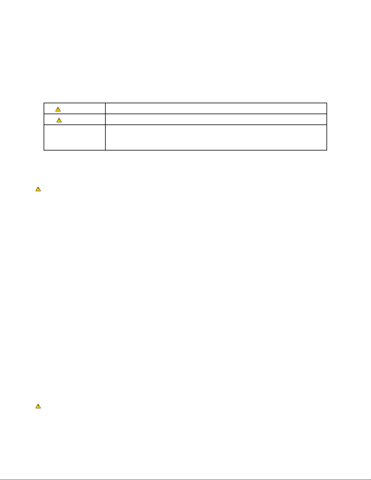
2. Use a Phillips screwdriver to remove the four
battery screws (Figure 5).
3. Unplug the black connector rst, then unplug the
yellow connector (Figure 6).
CAUTION!
Pull on the connectors, not on the wires. You
don’t want to pull the wires out of the connectors.
4. Follow the steps above to remove the battery
from the other side of the One S1.
WARNING!
Do not touch any internal electrical components
until after you have removed BOTH batteries and
pressed the ON/OFF button to discharge the
residual power. Failure to do so could result in
serious bodily injury from electric shock.
5. Press and hold the ON/OFF button until all
lights are off in order to discharge any power
remaining in the One S1.
Installation
1. Install in the reverse order of removal, being
careful not to pinch the battery wires.
NOTE
Do not overtighten the battery fasteners or you
may strip the plastic mounting posts.
Figure 5: Remove the four screws
Figure 6: Unplug the connectors
1st
2nd
Batteries
16 One S1
Battery Test
Tools Required
• Multimeter
Removal
1. Remove both battery covers (page14).
2. Remove both batteries (page15).
WARNING!
Do not touch any internal electrical components
until after you have removed BOTH batteries and
pressed the ON/OFF button to discharge the
residual power. Failure to do so could result in
serious bodily injury from electric shock.
3. Press the ON/OFF button until all lights are off to
discharge any power remaining in the One S1.
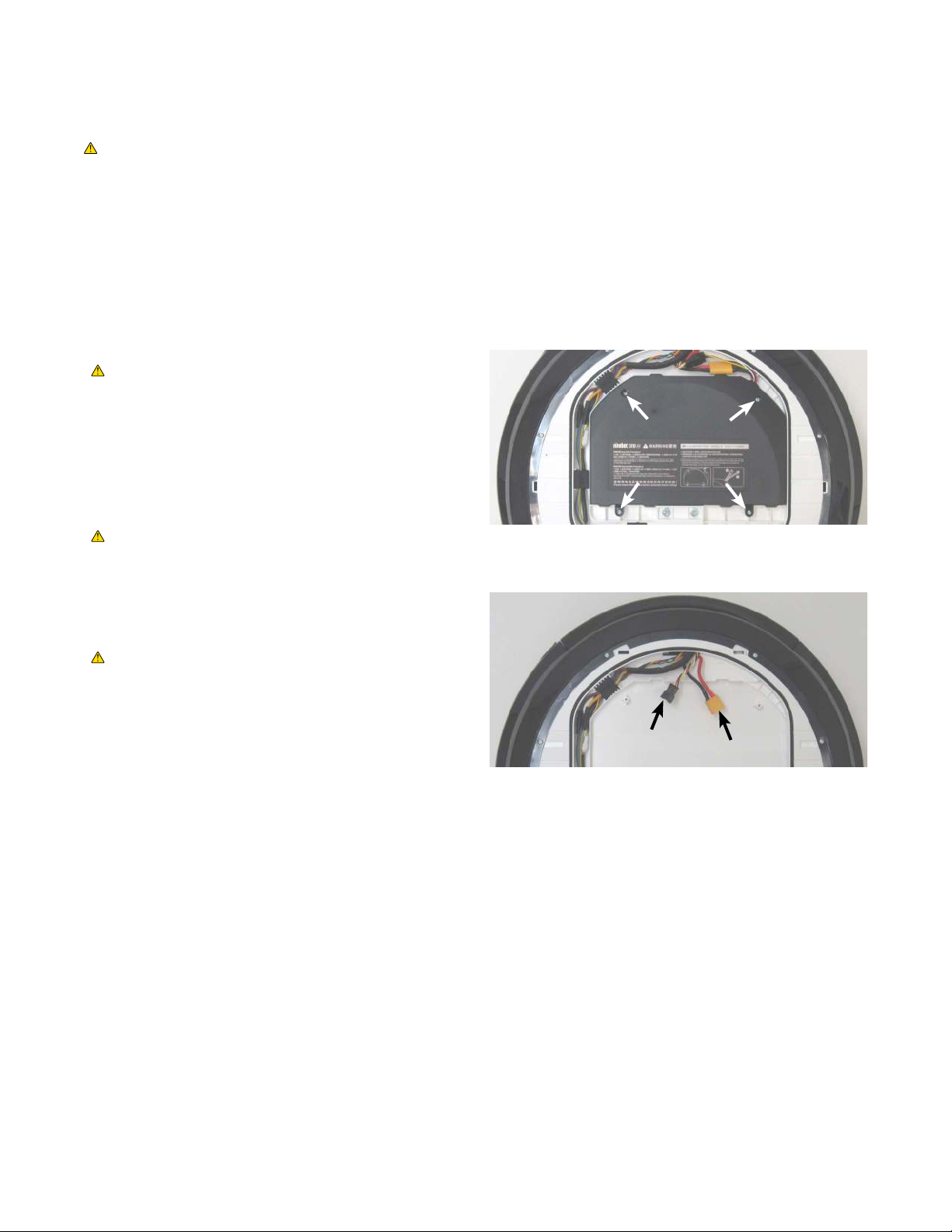
4. Set the multimeter to measure DC voltage.
5. Measure the battery voltage. Probe the battery’s
yellow connector, as shown in Figure 7.
6. The voltage should be 50–62 VDC. If it is higher
or lower there is a problem with the battery.
Contact Segway (page3) for a replacement
battery.
CAUTION!
When measuring battery voltage with a
multimeter, be careful not to short the test
probes or the two pins in the battery connector.
Doing so could result in a hazardous release of
stored energy.
Installation
1. Install the battery (page15).
Figure 7: Measure the DC voltage

17
Pedals
Service Manual
Pedals
Overview
There are two pedals, one on each side of the unit.
When to Replace
Replace a pedal when it is cracked, bent, or otherwise broken.
Pedals
18 One S1
Pedals
Tools Required
• 2.5 mm hex wrench
• 5 mm hex wrench
• Punch
Removal
Make sure the One S1 is powered off and the
charger is not connected.
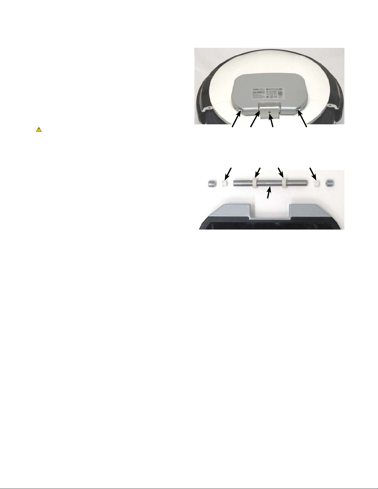
1. Loosen the set screw in the bottom of the bracket
(Figure 8).
2. Remove the end fasteners from both ends of the
pedal (Figure 8).
NOTE
You may need to use signicant force to break
the tension when removing these fasteners.
3. Using a punch or similar tool, tap out the rod.
4. Retain the bushings and spacers for installation.
Installation
1. Install in the reverse order of removal.
NOTE
Be sure to install the bushings and spacers as
shown in Figure 9.
Figure 8: Remove the pedal fasteners
Figure 9: Retain the bushings and spacers
Rod
Bushings
Spacer Spacer
End Fastener End FastenerSet ScrewRod

Service Manual 19
Pedals
Pedal Components
Each pedals is composed of:
• Base
• Cover
• Grip tape, small
• Grip tape, large
Holding the cover onto the base are:
• Threaded inserts (6 per pedal)
• M4x10 athead screws (6 per pedal)
Tools Required
• 2.5 mm hex wrench
Disassembly
Make sure the One S1 is powered off and the
charger is not connected.
NOTE
You can perform these steps with the pedal still
attached to the unit, however it is easier if you
remove the pedal rst (page18).
1. Peel both pieces of grip tape off the pedal and
discard (Figure 10).
2. Using a 2.5 mm hex wrench, remove the six
fasteners.
3. Separate the pedal cover from the pedal base
(Figure 11).
4. To remove threaded inserts (Figure 12): insert a
screw into the threaded insert, then tighten the
screw to press the threaded insert out.
Assembly
1. To install threaded inserts (Figure 13): orient the
threaded insert with the knurled edge up and
press it rmly into the hole.
2. Install in the reverse order of removal.
WARNING!
Always install new grip tape. Old/reused grip
tape could come loose while riding.
Figure 10: Grip tape removed
Knurled edge up
Figure 11: Pedal cover (left) and base (right)
Figure 12: Threaded insert, present (left) and absent (right)
Figure 13: Threaded insert

Pedals
20 One S1
Other manuals for NINEBOT ONE S1
1
Table of contents
Other Segway Bicycle manuals


