Seiko Z120 User manual

QUARTZ TIME RECORDER
USER'S MANUAL
1
1. The details of this User's Manual are subject to change without prior notification.
2. This User's Manual has been prepared with the utmost care to cover all aspects of the time
recorder's use.
If you feel, however, that some explanations are inadequate, unclear, or difficult to
understand, please do not hesitate to contact the dealer or the shop from whom you have
purchased your Time Recorder.
3. Be sure to use your Time Recorder after you have fully understood the hardware and
software specifications and limits.
4. No part of this publication may be reproduced, stored in a retrieval system, or transmitted,
in any form or by any means, mechanical, photocopying, recording or otherwise.
5. Place the time recorder at the position close to the wall outlet so that it is easily accessible
to disconnect.
6. This device is not intended for use in the direct field of view at visual display workplaces.
To avoid incommoding reflections at visual display workplaces this device must not be
placed in the direct field of view.
INTRODUCTION
Thank you for purchasing our Quartz Time Recorder. For safe and
proper operation, please carefully read this manual before using it and
save it for reference.
Q0910-61200
ALL RIGHTS RESERVED
©2013

TABLE OF CONTENTS
3
5
5
5
7
7
8
10
11
12
12
12
13
13
13
14
15
15
16
17
18
19
20
23
25
25
25
26
27
29
29
30
30
31
32
1. PRECAUTIONS
2. GETTING STARTED
- Packing Contents
- Overview
- SETUP: AC Adapter
- SETUP: Remove/Attach the Cover
- Installing the Ribbon Cassette
- Mounting Unit on Wall
- Connecting the External Time Signal
3. DAILY OPERATION
- Punching
- Override Punching
4. SETTING: Date and Time
- Setting the Display Hours
- Setting the Time
- Setting the Date
5. SETTING: Function
- Setting the Pay Period
- Setting the Day Advance Time
- Setting the Print Format
- Setting the Language
- Setting the Signal Length
- Setting the Weekly Program
- Setting the Daylight Saving Time
6. OTHERS
- Setting/Changing the Password
- Inputting the Password
- Reset
- List Printing
7. INFORMATION
- Error No. Causes and Actions
- Other Failures
- Environmental Conditions
- Default Settings
- Specifications
w

1. PRECAUTIONS
This user's manual is prepared for safe and proper use of the unit. Please follow all the
instructions to avoid possible danger to yourself or others and damage to the unit.
Signs
Various warnings and cautions are provided throughout this manual along with signs.
Remember each sign and its explanation listed below for your safety and proper
operation of the unit.
Caution
Warning
Improper handling may cause electric
shock DANGER.
DO NOT disassemble the unit.
"Don't" sign.
"Must-Do" sign.
Be sure to remove the line cord plug
from the outlet.
Do not disassemble the unit. There is a high voltage present inside, possibly leading to an
electric shock.
Do not use any voltage of the power source other than designated.
Do not share a single outlet with another plug. These may lead to fire or shock hazards.
Do not damage, break, or modify the power cord. Do not put a heavy object on, pull, or
forcefully bend the cord, either. These may damage the cord, possibly resulting in a fire or
electric shock.
If any anomaly occurs, for example, heat or smoke is generated or an odor is emitted, unplug
the unit immediately and contact your dealer for servicing. There is a danger that further use
may cause a fire or electric shock.
Do not modify the unit. Modifications may cause a fire and/or electric shock.
Warning
Improper handling may cause bodily accidents including
death and serious injury.
Improper handling may harm the human body or material.
e

If foreign matter should get in the unit (including a piece of metal, water, or liquid), disconnect
the plug from the outlet immediately and contact your dealer for servicing. There is a danger
that further use may cause a fire or electric shock.
Do not place the unit on an uneven or tilted surface. This may result in injuries due to the unit
dropping or falling off.
Do not put a water-filled container or a metal object on top of the unit. If water is spilled or the
metallic object slips inside, a fire or shock hazard may occur.
Do not place the unit near kitchen counter or humidifier. Oil, smoke, or steam generating from
them may cause fire or shock hazards.
Do not yank the power cord to disconnect from the outlet. Hold the plug with your hand to do
so, or the cord may be damaged, possibly leading to a fire or electric shock.
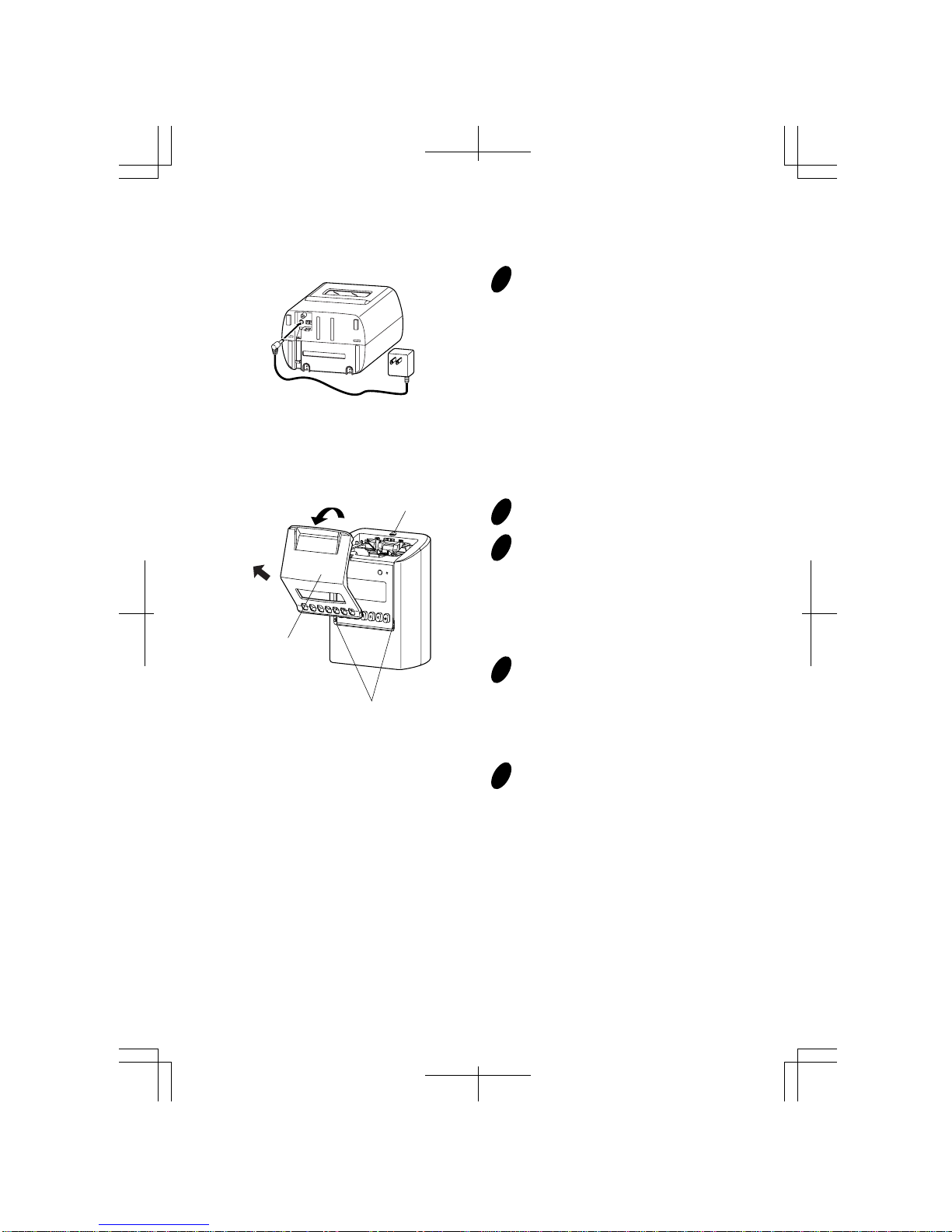
Remove the line cord plug from the outlet before transferring the unit, or it may damage the
cord, possibly leading to a fire or electric shock.
Make sure to insert the power plug as far as it will go. Improper insertion of the plug may
develop fire or shock hazards.
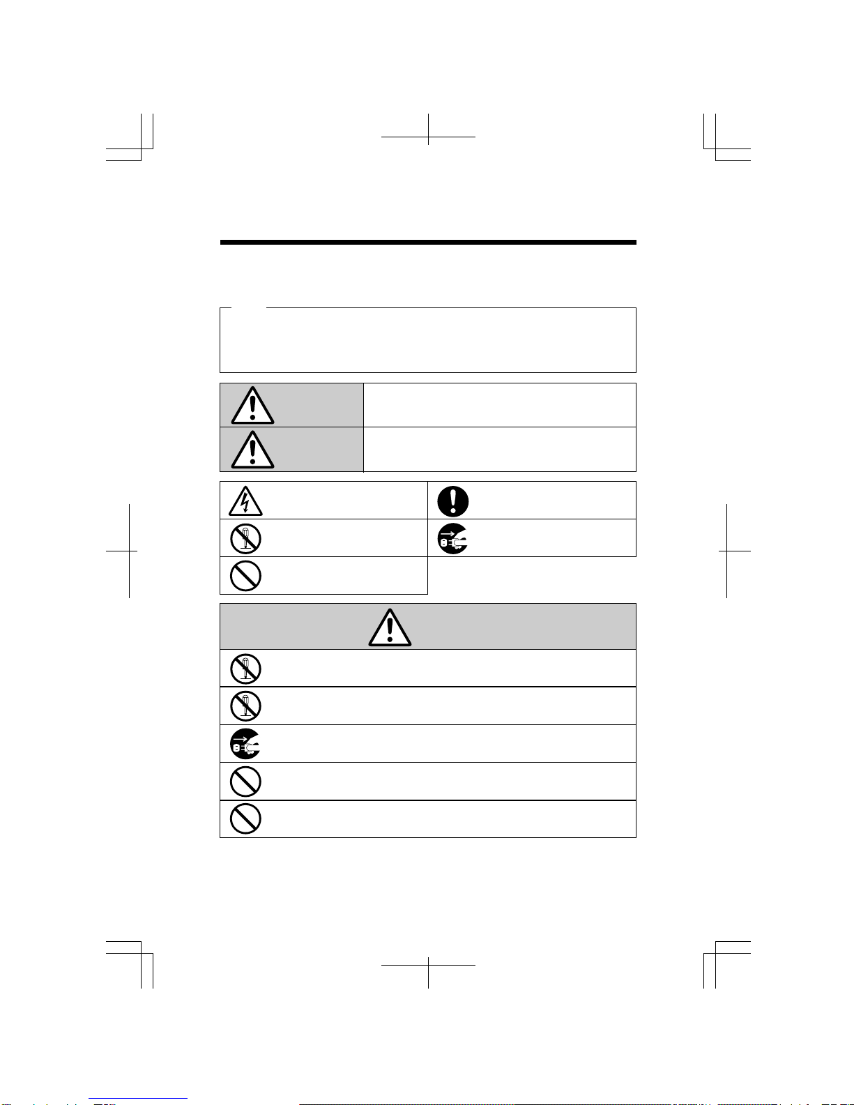
Do not insert or drop any other time card than specified into the slot. Such misuse may cause a
fire or electric shock.
If the unit should be dropped or the case be broken, unplug the unit and contact your dealer for
servicing. Further use may lead to a fire or shock hazard.
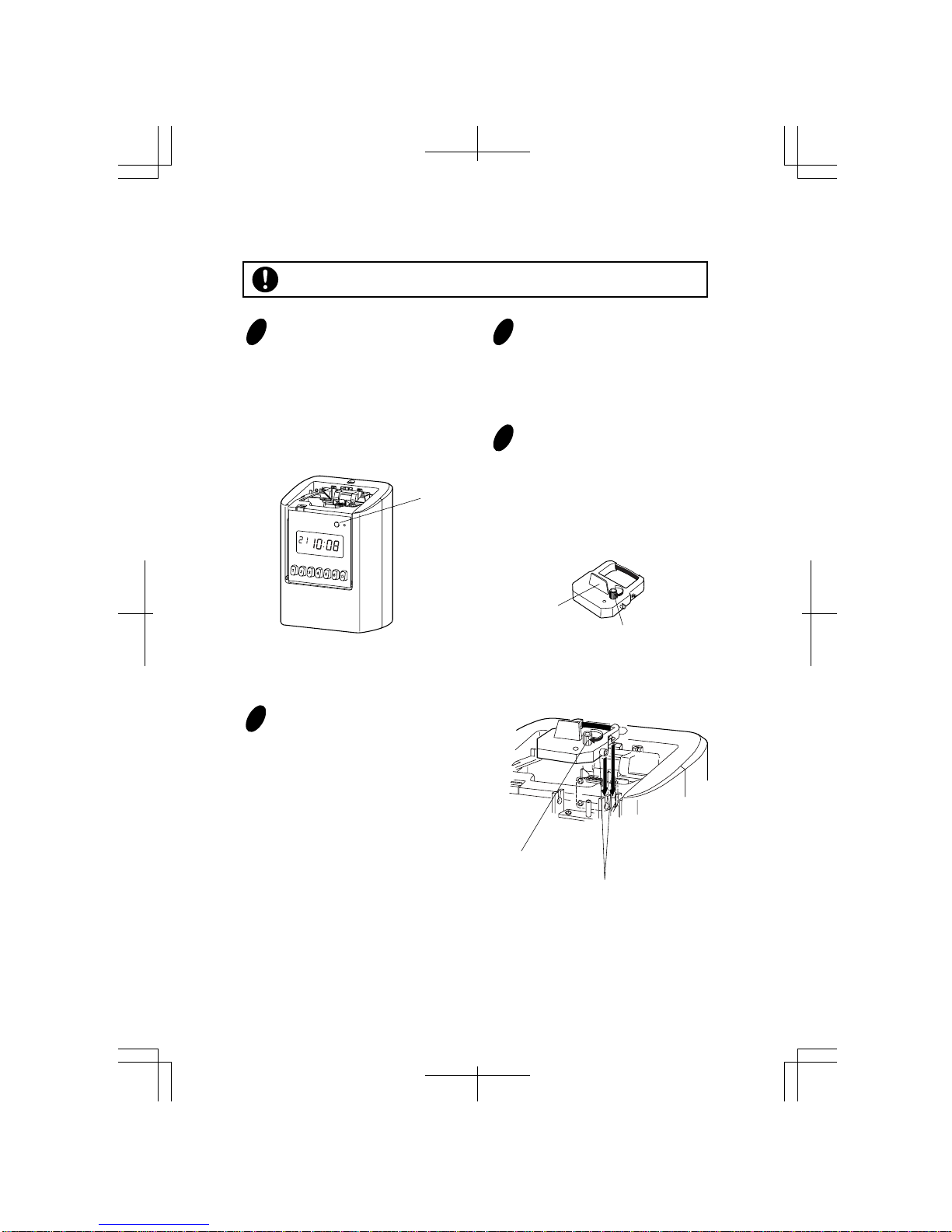
Be careful not to contact the print head, as you may get hurt or burned.
Do not install the unit in a humid or dusty environment. It may cause a fire or electric shock.
Do not plug or unplug the unit with a wet hand. You may get an electric shock.
Daily Care
For cleaning, turn the power off and wipe the case clean of dust and dirt with a dry
cloth, etc.
Caution
r

Overview
2. GETTING STARTED
Packing Contents
User's manual Wall mount
hardware Ribbon cassette
Keys
Daylight saving time indication
< Display (punching mode) >
Key hole
Cover
Display
Control buttons
Card slot
Wall-mounting
holes
Day of the week indication
Current date
AM/PM
indication
Current column indication Current time
t
AC adapter Small cover
and screw
AM PM

Button Label OTHER RESET
SETTING MODE
Control Buttons
PUNCHING MODE
Selectable items
SETTING
Select setting items
for DATE/TIME
Select setting items
for FUNCTION
Change (increment) flashing number
Change (decrement) flashing number
Set flashing number
Enter/Exit setting mode
DISPLAY HOURS
TIME
DATE
PAY PERIOD
DAY ADV. TIME
PRINT FORMAT
LANG.
SIGNAL LENGTH
WEEKLY PROGRAM
DAYLIGHT SAVING
Move to
1st column
Move to
2nd column
Move to 3rd column
Move to 4th column
Move to 5th column
Move to 6th column
Override punching
Password Setting
(Press both
buttons at the
same time)
List Printing
Ink Ribbon Change
Error Cancellation
(press for 3 sec.)
All clear Reset
(Press reset
button while
pressing
1 and 3
buttons)
1
2
3
4
5
6
Refer to "Reset" in this manual to learn how to use the RESET button.
DATE/TIME
FUNCTION
+
-
SET
SETTING
START/END
y
S
M
TWTFS
UOUEHRA
Z120
PASSWORD
WEEKLY
PROGRAM
DAYLIGHT
SAVING
SET
TIME DATE
DISPLAY
HOURS
DAY ADV.
TIME
PRINT
FORMAT
SETTING
LIST
SETTING START/END
Press
LANG.
PAY
PERIOD
FUNCTIONDATE/TIME
SIGNAL
LENGTH
Short : Setting
Long (3 sec.): Ribbon Change
Error Cancellation
123456
SETTING
Button
RESET
Switch
DATE/TIME
Button FUNCTION
Button Button Button SET
Button

Cover
Projections
Key Hole
<1>
<2>
u
SETUP: AC adapter
1Put the bottom face of a time recorder
toward you. Connect a plug of AC
adapter into the time recorder, and run
the cord into the groove on the bottom.
Then, plug the AC adapter into AC
outlet.
SETUP: Remove/Attach the Cover
1
2
3
4
Turn the key to unlock.
Remove the cover.
<1> Pull the top of the cover toward
you supporting the bottom side of the
cover.
<2> Pull it to front and upper
direction. Then, remove the cover.
Attach the cover.
Fit the right and left sides on the
bottom of the cover in projections of
the unit. Then, attach the cover in the
reverse order of <1> and <2> in step 2.
Turn the key to lock.

i
Place the ribbon cassette inside the
time recorder as shown in the figure.
Push the ribbon cassette until it snaps
into the clasps on both sides. If it is
difficult to insert the ribbon cassette,
try it while turning the knob.
Knob
Tab
Clasps
(located on both sides)
Knob
Installing the Ribbon Cassette
Remove the cover, and press
[SETTING] button for three seconds.
Then, display will change as follows
and a ribbon cassette moves to the
replacement position.
Note: Ribbon cassette is not factory
installed.
When you replace an installed ribbon
cassette to a new one, pull up the ribbon
cassette just above with the tab.
Make sure the power is on before installing.
[SETTING]
button
12
Turn the knob of the new ribbon cassette
in the same direction as the arrow to
tighten the ribbon.
Note: Must not turn the knob in the
opposite direction. Improper handling
causes malfunction of a ribbon cassette.
3
4

Install the ribbon cassette so that the ribbon is between the print head and the ribbon
mask (see the figure on the left). Printing will not come out properly if the ribbon is
placed behind the ribbon mask (see the figure on the right).
When you finish changing the ribbon
cassette, press [SETTING] button for
three seconds to be back to normal
punching mode.
Turn the knob of the ribbon cassette in
the direction of the arrow to tighten
the ribbon.
Knob
Print head
Ribbon mask
Ribbon
Print head
Ribbon mask
Ribbon
CORRECT WRONG
5
67
o

Mounting Unit on Wall
The supplied screws are intended
for use on a thick wooden wall
or wooden column. Do not use
them on any other materials.
There is a danger that the unit
may come off if used on the
other materials.
Install wall mount screws (supplied)
into a wall 10 cm (3-15/16") apart. Be
sure to keep about 3 mm (1/8") of the
screw head out of the wall. Use
template on the bottom of the back
side of this manual if you prefer.
10cm (3-15/16")
3mm
(1/8")
Mount the wall mount fittings
as shown on the right.
Plug the unit into power, and
the unit is ready to use.
The unit can be mounted on a wall using the supplied mounting fittings.
1
2
3
!0
Wall
Wall Mount Template
Screws
Make sure the power is off before mounting.

Connecting the External Time Signal
When a signal is activated the internal contacts close completing the circuit. These internal
contacts are "dry" and supply no voltage. Voltage applied to these contacts must not exceed
30 volts.
Connection Specifications for External Time Signal Contact
• Contact output: dry contact
• Contact capacity: 30V, 2A or less (Resistive) and SELV (Safety Extra-LowVoltage)
Disconnect the Z120 fromAC power before connecting.
Improper connection may cause a malfunction of the unit.
Insert wires into two terminals for external time signal relay while pushing the button with a
pointed implement.
Internal
Relay
Terminal
Less than 30V
CAUTION:
Terminals
Buttons
!1
<1>
<2>
<3>
Screw
When connecting, attach
the small cover as shown.

3. DAILY OPERATION
• Do not bend, fold, and cut time
cards, and do not put any label
and sticky note on time cards.
• Do not let any object except
time cards get into the slot.
• Do not forcefully push in a card
and pull out a card.
!2
Override Punching
In case that you want to punch later than "Day Advance Time", you can use "Override
Punching". Using "Override Punching", your next punching is in the desired column on the
same line with the previous day. To identify override punching, the punching will have
special mark " " or " ".
qPress [ ] button before inserting a time card. When you press [ ] button, the 6th
column is automatically selected.
wIf necessary, press a button from the 1st to the 5th column to specify punching column,
while the " " mark is flashing near [ ] button.
Note: You can cancel "Override Punching" when you press [ ] button once again while
the " " mark is flashing near [ ] button.
eInsert a time card into card slot with printing side to the front. The time card is
automatically pulled in, printed, and then ejected.
Punching
Once AC adapter is plugged into an outlet, time recorder can be used immediately.
Note:
- Make sure to install a ribbon cassette in it.
- Refer to "4. SETTING: Date and Time" and "5. SETTING: Function" in this manual, if
you need to change settings.
qPress a button corresponding to a column you want to punch.
wInsert a time card into card slot with printing side to the front. The time card is
automatically pulled in, printed, and then ejected.
Note:
- You can punch up to 6 times a day.
- Once the column is selected by a button, the selected column remains unchanged even
after your punching. (Once setting is changed , punching column will be back to the
original position.)
- By setting weekly program, punching column can be moved automatically.
1st Column
2nd Column
3rd Column 4th Column
5th Column
6th Column
Override

4. SETTING: Date and Time
!3
Setting the Time
Below image shows an example set at 8:30 PM.
qRemove the cover, and press [SETTING] button to enter setting mode.
Note: When "9999" appears on display, input the password first.
wPress [DATE/TIME] button and position " " under "TIME" mark.
ePress [+] or [-] button to adjust number to current hour, and press [SET] button to accept.
Note: When you change time, second will be back to 0 second automatically.
rSet current minute in the same manner.
tPress [SETTING] button to exit setting mode, and attach the cover.
Note: If you press [DATE/TIME] button before pressing [SETTING] button, you can
continue setting for date and time.
Setting the Display Hours
"Display hours" is the format that the hours appear on the clock face. Once you select
"AM/PM" for display hours, time in setting mode is also indicated in "AM/PM" format.
Below image shows an example that "24hours" is chosen.
qRemove the cover, and press [SETTING] button to enter setting mode.
Note: When "9999" appears on display, input the password first.
wPress [DATE/TIME] button, and position " " under "DISPLAY HOURS" mark.
ePress [+] or [-] button to select number 1 or 2, and press [SET] button to accept.
rPress [SETTING] button to exit setting mode, and attach the cover.
Note: If you press [DATE/TIME] button before pressing [SETTING] button, you can
continue setting for date and time.
Selectable numbers and Options
Hour
12AM
11PM
No.
0
23
No.
1
2
No.
00
59
Minute
00
59
DISPLAY
HOURS
TIME
Type of Hours
AM/PM
24 hour
Example
PM 3:30
15:30
Selectable numbers and Options
Minute
Second Hour
Type of Hours

!4
Setting the Date
Below image shows an example of December 20, 2013.
qRemove the cover, and press [SETTING] button to enter setting mode.
Note: When "9999" appears on display, input the password first.
wPress [DATE/TIME] button, and position " " under "DATE" mark.
ePress [+] or [-] button to adjust number to the last two digits of current year, and press
[SET] button to accept.
rSet the current month and date in the same manner.
tPress [SETTING] button to exit setting mode, and attach the cover.
Note: If you press [DATE/TIME] button before pressing [SETTING] button, you can
continue setting for date and time.
No.
1
31
Date
1
31
Selectable numbers and Options
No.
1
12
Month
January
Decembe
r
No.
00
99
Year
2000
2099
Date
Year Month
DATE

5. SETTING: Function
!5
Setting the Pay Period
You can choose the length of one period using one card, and set the ending date/day.
Below image shows an example that "Semi-monthly" is chosen.
Selectable numbers and Options
No.
1
2
3
4
Type
Monthly
Weekly
Bi-weekly
Semi-
monthly
Order Option
1-31
0-6
0-13
1-31
How to set the Ending Date/Day
Set the ending date of the month.
Set the desired pay period ending day, which comes
within 7 days from today. (Today is counted as 0.)
Set the desired pay period ending day, which comes
within 14 days from today. (Today is counted as 0.)
Set two ending dates of the month.
(Can't set the same date.)
Type
1st Ending Date
(Semi-monthly only)
PAY
PERIOD
qRemove the cover, and press [SETTING] button to enter setting mode.
Note: When "9999" appears on display, input the password first.
wPress [FUNCTION] button, and position " " under "PAY PERIOD" mark.
ePress [+] or [-] button to select period type, and press [SET] button to accept.
rPress [+] or [-] button to select number of your desired ending date/day according to the
period type, and press [SET] button to accept. When you choose Type 4 (Semi-monthly),
you need to set two dates of the month.
tPress [SETTING] button to exit setting mode, and attach the cover.
Note: If you press [FUNCTION] button before pressing [SETTING] button, you can
continue setting for function.
Ending Date/Day

!6
Setting the Day Advance Time
The day advance time refers to the time when printing shifts to the next line on a time card
for the next day. With this function, you can adjust from what time to what time of the day
will be regarded as the same day on a time card.
Below image shows an example that Day Advance Time is set to 5:00AM.
qRemove the cover, and press [SETTING] button to enter setting mode.
Note: When "9999" appears on display, input the password first.
wPress [FUNCTION] button and position " " under "DAY ADV. TIME" mark.
ePress [+] or [-] button to select hour of the line shift time, and press [SET] button to
accept.
rSet the minute of the line shift time in the same manner.
tPress [SETTING] button to exit setting mode, and attach the cover.
Note: If you press [FUNCTION] button before pressing [SETTING] button, you can
continue setting for function.
Hour
12AM
11PM
No.
0
23
No.
00
59
Minute
00
59
Selectable numbers and Options
Hour of
the line
shift time
Minute of
the line
shift time
DAY ADV.
TIME

!7
Setting the Print Format
Below image shows an example that "Date, 24hour" and "Regular Minutes" are chosen.
qRemove the cover, and press [SETTING] button to enter setting mode.
Note: When "9999" appears on display, input the password first.
wPress [FUNCTION] button, and position " " under "PRINT FORMAT" mark.
ePress [+] or [-] button to select number of Print Format, and press [SET] button to accept.
rPress [+] or [-] button to select number of Minute Type, and press [SET] button to
accept.
tPress [SETTING] button to exit setting mode, and attach the cover.
Note: If you press [FUNCTION] button before pressing [SETTING] button, you can
continue setting for function.
1
2
3
4
5
6
15 : 30
Mo 15 : 30
15 : 30
PM 3 : 30
3 : 30 P
Mo 3 : 30 P
Date, 24hour
Day of the week, 24hour
24hour
12hour
Date, 12hour
Day of the week, 12hour
Print FormatNo. Example:
Print Format: Selectable numbers and Options
1
28 : 43
8.71
Regular Minutes (1/60)
Hundredths (1/100)
Minute Type Print Example:
8 : 43
No.
Minute Type: Selectable numbers and Options
Print Format Minute Type
PRINT
FORMAT
2121

!8
Setting the Language
You can select desired language from the following 6 options for day of the week indication
on time cards.
This setting is available only when you select a print format which includes day of the week.
Below image shows an example that English is chosen.
qRemove the cover, and press [SETTING] button to enter setting mode.
Note: When "9999" appears on display, input the password first.
wPress [FUNCTION] button, and position " " under "LANG." mark.
ePress [+] or [-] button to select number of Language, and press [SET] button to accept.
rPress [SETTING] button to exit setting mode, and attach the cover.
Note: If you press [FUNCTION] button before pressing [SETTING] button, you can
continue setting for function.
Language
English
Spanish
German
French
Italian
Portuguese
No.
1
2
3
4
5
6
Example:Thursday
TH 15:30
JU 15:30
DO 15:30
JE 15:30
GI 15:30
QI 15:30
Selectable numbers and Options
Language
LANG.

!9
Setting the Signal Length
You can set desired signal length up to three patterns. Length of each pattern is selectable
from 1 to 30 seconds.
Note:Refer to "Connecting External Time Signal" for how to connect to external devices
and its specifications in this manual.
Below image shows an example that Signal Pattern No.1 is set to 30 seconds signal.
qRemove the cover, and press [SETTING] button to enter setting mode.
Note: When "9999" appears on display, input the password first.
wPress [FUNCTION] button, and position " " under "SIGNAL LENGTH" mark.
ePress [+] or [-] button to select number of signal pattern, and press [SET] button to
accept.
rPress [+] or [-] button to select seconds of signal length, and press [SET] button to
accept.
tPress [SETTING] button to exit setting mode, and attach the cover.
Note: If you press [FUNCTION] button before pressing [SETTING] button, you can
continue setting for function.
Signal Pattern
1
3
No.
1
3
No.
1
30
Length
1 second
30 seconds
Selectable numbers and Options
Length
Signal Pattern
SIGNAL
LENGTH

@0
Setting the Weekly Program
Weekly program enables a time recorder to memorize the following features for specified
time. Up to 24 programs can be set.
Note:
- When you select the option "5" or "6" in the "Print Format" setting, the special mark
appears instead of AM/PM indication, and will change to " " in the afternoon.
- When you choose " " in the order option of features, it means that there's no command
and no change.
- To set Signal Pattern, refer to "Setting the Signal Length" in this manual.
Example
Applicable Monday - Friday
Time
Printing Column
Special Mark
External Signal
No.
1
2
3
Feature
Column
Special Marking
Signal Pattern
Order Option
1-6, --
1, 2, --
1, 2, 3, --
Explanation
Automatic printing
column shift
Special Mark " " for
irregular recognition
Output Signal
Action
Select column to shift
Select on/off of special marking
1: turn ON 2: turn OFF
Select Signal Pattern
1st Column 2nd Column 3rd Column 4th Column 5th Column 6th Column
5:00 9:00 12:00 17:00 17:30 20:00 5:00
Next DayDay Advance Time
ON
Pattern 1 Pattern 2 Pattern 3 Pattern 3
Program No. 12345
9:00
2
1
1
12:00
3
- -
- -
17:00
4
2
2
17:30
5
- -
3
20:00
6
- -
3
off
on
off
SUN
MON
FRI
SAT
off
on
off
off
on
off
off
on
off
off
on
off
Applying Time
Feature 1 (Column)
Feature 2 (Special Mark)
Feature 3 (Signal Pattern)
Applicable days
of the week
Selectable numbers and Options
Table of contents
Other Seiko Clock manuals
Popular Clock manuals by other brands

Arbiter Systems
Arbiter Systems 1205B Operation manual

Lowrance
Lowrance LDT-3003 Installation and operation instructions

TFA
TFA UMIO PLUS 60.2553 instruction manual

Oregon Scientific
Oregon Scientific rm318p User instructions

Sapling
Sapling SBT 3000 Series Installation and programming manual

Valcom
Valcom VIP-D425DS user guide