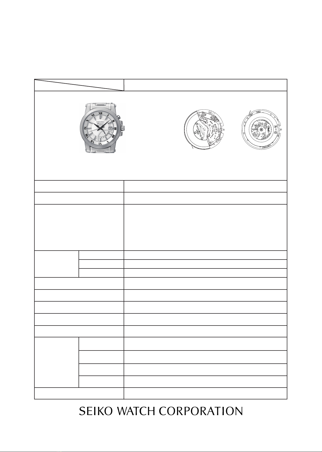
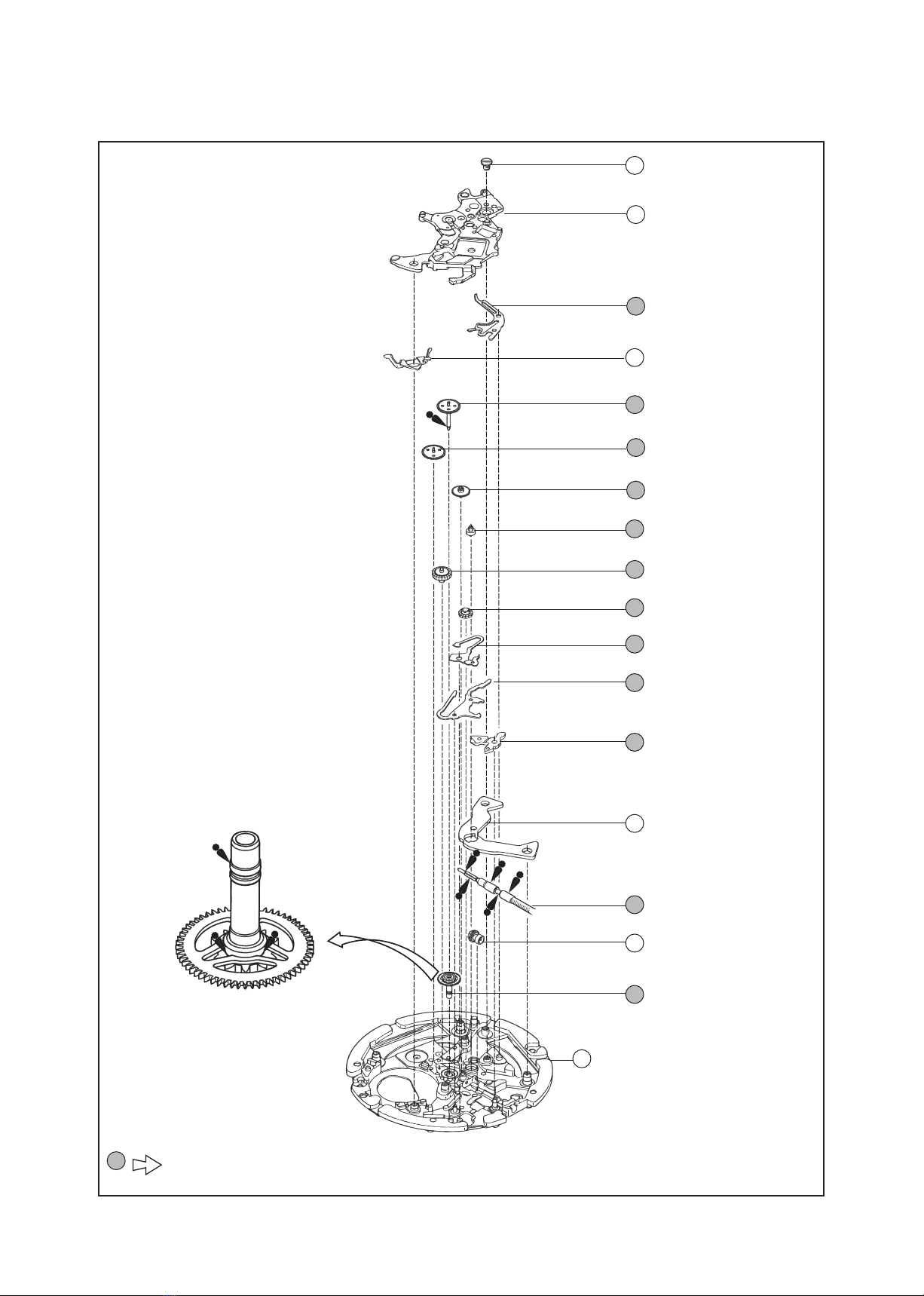
Seiko 5M84A User manual

[SPECIFICATIONS]
Item Cal. No.
Power generator
Rechargeable
battery
Monthly rate: less than 15 seconds (worn on the wrist at temperature
range between 5 and 35 ºC)
Nil
Use 10-second gate
Movement: less than 0.80 µA
Circuit block: less than 0.20 µA
Automatic generating system
MT920 Titanium carbon lithium rechargeable battery
0.9V - 2.20V
From full charge to stoppage: approximately 6 months
6 jewels
1/21
PARTS LIST/TECHNICAL GUIDE
KINETIC Cal. 5M84A
5M84A
Driving system
Additional function
Crown operation
Loss/Gain
Regulation system
Gate time for rate measurement
Current consumption
Power supply
Operating
voltage range
Duration of
charge
Number of jewels
Interval of hands movements
Normal position
1st click position
2nd click position
Coil resistance
• 3hands (Hour/Minute/Second)
•Calendar Date(datedial)
Day (retrograde day indicator)
1 second
Steppingmotor2pieces
• Powerreserveindicator(secondhand)
• Energydepletionforewarningfunction
• Overchargepreventionfunction
• Electroniccircuitresetfunction
• Dayanddatecorrectionfunction
• Secondhandstopfunction
Free
Day and date setting
•
Diameter
Outside :
Ø 27.6 mm
Casing :
Ø 27.0 mm
• Height:4.3
mm
Timesetting(HourandMinute)
5
M
8
4
A
Movement
Coil block: 1.70 - 2.10 KΩ
Generating coil block: 280 - 380Ω

Cal. 5M84A
2/21
SPECIFICATIONS
10 seconds 20 seconds 30 seconds
Between 7 days and 1
month
Approx.
1 month
Approx. between
4and6months
Between
1 and 7 days
5 seconds
POWERRESERVE
QUICKMOVEMENTOF
SECONDHAND
SEIKO KINETIC Cal. 5M84 is an analogue quartz watch equipped with the Kinetic technology
developedbySEIKO.Itgenerates theelectric energytopowerthewatch,utilizing themovementof
yourbody,andstoresitintherechargeablebattery,whichrequiresnoperiodicalreplacementunlike
conventional button-type batteries.
1. Whenthewatch stopscompletely,or ifyound
thesecondhandmovingattwo-secondintervals,
swing the watch from side to side at a rate of
twice a second.
1. By swinging the watch
2. By using the KINETIC Energy Supplyer YT02A
2. 250 swings will reserve up to 1 day of power.
The second hand will start moving at one-second intervals.
Setthecrowntothe5Mposition.
• Make sure that the watch is correctly
positioned as it may affect the amount of
power generated.
• Theamountofpowergeneratedmayvary
depending the models of the watch.
5M
Cal.5M84Aisequippedwithapowerreserveindicator.Thecurrentpowerreservecanbecheckedby
reading the posisiton of the second hand after pressing the button at the 2 o'clock position.
* The second hand will resume normal movement after the indicated 5, 10, 20 or 30 seconds have
elapsed.
* To allow easy reading of the second hand, press the button when the second hand is at the 12 o’clock
position.
* It is recommended that the watch be swung further until 2 days of power is reserved. As a
guideline of recharging, additional 200 to 250 swings, about 450 to 500 swings in total will
reserve 2 days of power.
POWER RESERVE INDICATOR
POWER
RESERVE
NUMBER OF
SWINGS 250 450 ~ 500
1 DAY 2 DAYS
APPROX.
6 MONTHS
FULL
FEATURES
HOW TO CHARGE THE WATCH

Cal. 5M84A
3/21
PARTS LIST
Disassembling procedures Figs. : 1 65
Reassembling procedures Figs. : 65 1
Lubricating: Types of oil
Watch Oil AO-3
Watch Oil AO-2
SEIKOWatchOilS-6
Siliconeoil500,000c.s.
Oil quantity
Normalquantity
Please see the remarks on the following pages.
Lubricatingofsomepartsisshownin“II.REMARKSONDISASSEMBLINGANDREASSEMBLING”.
1 CASEBACK
2 CASEBACKGASKET
4 MOVEMENT
7 BUTTONSPRING
5 BUTTONSPRINGCLIP
6 BUTTON
3 CROWN
[CASING PARTS ASSEMBLY]

26
27
28
0012354
DAY LEVER GUARD SCREW
0837503
DAY LEVER GUARD
1002516
DAY WHEEL
1017503
DAY LEVER
1018504
DAY LEVER SPRING
0871502
DAY STAR WHEEL
0491735
DIAL WASHER
0022247
DAY LEVER BRIDGE SCREW
0808514
DATE DIAL GUARD
0878***
DATE DIAL
0810660
DATE JUMPER
0989660
INTERMEDIATE DAY CORRECTOR WHEEL
0737670
DATE CORRECTOR WHEEL
0962670
INTERMEDIATE DATE CORRECTOR WHEEL
0816670
DATE DRIVING WHEEL
0271607
HOUR WHEEL
DAY LEVER BRIDGE
HOLDING RING FOR DIAL
0866***
11
12
14
15
16
17
18
19
20
21
22
23
24
25
SPACER FOR DIAL
10 4408564
4408559
X
II
I
II
III
IIII
I
I
V
VI
V
V
II
I
XI
X
XI
SEIKO
PRE MIER
KIN ET IC
MON
TUE
WED
THU
FRI
SAT
SUN
RETROGRADE DAY HAND
DIAL
HOUR, MINUTE AND SECOND HANDS
9
8
13
Cal. 5M84A
4/21
PARTS LIST
Please see the remarks on the following pages.
Lubricatingofsomepartsisshownin“II.REMARKSONDISASSEMBLINGANDREASSEMBLING”.
[CALENDAR MECHANISM/
DIAL AND HANDS SETTING]

Cal. 5M84A
5/21
PARTS LIST
Please see the remarks on the following pages.
Lubricatingofsomepartsisshownin“II.REMARKSONDISASSEMBLINGANDREASSEMBLING”.
29 OSCILLATINGWEIGHTSCREW
0022490
30 OSCILLATINGWEIGHT
0500665
31 OSCILLATINGWEIGHTWHEEL
1002662
32 RECHARGEABLEBATTERYCLAMPSCREW
0022247
33 RECHARGEABLEBATTERYCLAMP
4225519
35 RECHARGEABLEBATTERYUNIT
302324T
36 CIRCUITBLOCKCOVERSCREW
0022247
37 CIRCUITBLOCKCOVER
4457760
38 CIRCUIT BLOCK
4000789
39 OSCILLATINGWEIGHTBRIDGESCREW
0022247
40 CONDUCTIVEPLATE
4459500
41 OSCILLATINGWEIGHTBRIDGE
0198662
42 GENERATINGCOILBLOCK
4002514
43
INTERMEDIATEWHEELFORGENERATINGROTOR
1002660
34 INSULATORFORRECHARGEABLEBATTERY
4216519
44 GENERATINGROTOR
4146518
45 GENERATINGSTATOR
4239519
46 COILBLOCKSCREW
0022247
47 COILBLOCK
4002516
[AUTOMATIC GENERATING
MECHANISM/ELECTRONIC
CIRCUIT]

Cal. 5M84A
6/21
PARTS LIST
Please see the remarks on the following pages.
Lubricatingofsomepartsisshownin“II.REMARKSONDISASSEMBLINGANDREASSEMBLING”.
49 TRAINWHEEL BRIDGE
0125661
50 TRAINWHEELSETTINGLEVER
0391660
51 RECHARGEABLEBATTERY
CONNECTION(+)
4271515
52 FOURTHWHEELANDPINION
0241667
54 FIFTHWHEELANDPINION
0701670
55 STEPROTOR
4146531
56 MINUTEWHEEL
0261670
57 SETTINGWHEEL
0281670
58 SWITCHLEVER
4450730
59 YOKE
0384661
60 SETTINGLEVER
0383662
61 ROTORSTATOR
4239559
62 SETTINGSTEM
0351 ***
63 CLUTCHWHEEL
0282672
64 CENTERWHEELANDPINION
0221667
65 MAINPLATE
0100564(FORSTANDARDCASETYPE)
53 THIRDWHEELANDPINION
0231530
48 TRAINWHEELBRIDGESCREW
0022247
[GEAR TRAIN MECHANISM/
SETTING MECHANISM]

Cal. 5M84A
7/21
PARTS LIST
lHow to find the correct parts, if not determined by 4 digit caliber number
Following parts are determined based on the design of watches, such as hands height, dial color,
and design of cases. Please refer to the SEIKO WATCH PARTS CATALOGUE in order to choose
corresponding parts.
Remarks
0022247
• DAYLEVERBRIDGESCREW (3PCS.)
• RECHARGEABLEBATTERYCLAMPSCREW(2PCS.)
• CIRCUITBLOCKCOVERSCREW (2PCS.)
• OSCILLATINGWEIGHTBRIDGESCREW(2PCS.)
• COILBLOCKSCREW (1PC.)
• TRAINWHEELBRIDGESCREW (1PC.)
0022490
• OSCILLATINGWEIGHTSCREW (1PC.)
0012354
• DAYLEVERGUARDSCREW (1PC.)
11 HOLDINGRINGFORDIAL0866***
22 DATEDIAL
Part code Position of crown Position of calendar
frame Colorofgure
Color of back
ground
0878B42 3 o'clock 3 o'clock White Black
0878B43 3 o'clock 3 o'clock Black White
0878 B25 3 o'clock 6 o'clock White Black
0878 B26 3 o'clock 6 o'clock Black White
62 SETTINGSTEM0351653
ThetypeofSETTINGSTEMisdeterminedbasedonthedesignofcases.
CheckthecasenumberandrefertoSEIKOCasingPartsCataloguetochooseacorrespondingpart.
SCREWS

Cal. 5M84A
8/21
PARTS LIST
lTools and consumables required for disassembling/reassembling
• Movement holder
Universalmovementholder(S-682)
• Watch oils
SEIKOwatchgrease(S-6)andwatchoils(AO-3andAO-2)
S-6 AO-2
AO-3

Cal. 5M84A
9/21
TECHNICAL GUIDE
REMARKS ON DE-CASING/CASING/DIAL AND HAND SETTING
lHow to set the RETROGRADE DAY HAND at the first day position
MON
TUE
WED
THU
FRI
SAT
SUN
Make sure the DAYLEVER and the DAYSTARWHEELare at the 1st day position by listening the sound
when changing the day.
1. Turnthecrownclockwiseattherstclickpositionuntil
youheartheuniquesoundwhenchangingfrom7th
day to 1st day.
2. Install the hand pointing to the 1st day (MON)
position.
MON
TUE
WED
THU
FRI
SAT
SUN
3. Make sure the day changes correctly and smoothly
byturningthecrownattherstclickposition.
MON
TUE
WED
THU
FRI
SAT
SUN
8 RETROGRADEDAYHAND

Cal. 5M84A
10/21
TECHNICAL GUIDE
35 RECHARGEABLEBATTERYUNIT
ThoughtheRECHARGEABLEBATTERYUNITforCal.5M8Seriesisofacompletelydifferentfrom
Cal.5M6Series,theyhaveacloseresemblanceinshape.Theycanbediscriminatedbytheshapes
oftheirminusleadterminalsasillustratedbelow.MakesuretouseappropriateRECHARGEABLE
BATTERYUNIT,inservicingbycheckingthis.
Minus lead terminal
[ RECHARGEABLE BATTERY UNIT
for Cal. 5M8 Series ]
•How to remove
Insertthetipoftweezersintothe“C”モportion
gapintheillustrationatright,andpryupthe
R E C H A R G E A B L E B AT T E R Y U N I T t o r e m o v e i t .
•How to install
Setthe“A“ portion of the minus lead terminal
totheholeofthemainplate,andpushthe
“B“ portion down vertically so that the
RECHARGEABLE BATTERY UNIT is well
seated in position.
Note: Takecarenottoshort-circuitthe(+)and
(-)terminals,asthiswilldeterioratethe
battery unit.
“A“portion
Main plate
メ“C“portion Minus lead terminal
Rechargeable
battery plus
terminal
メ“B“portion
Minus lead terminal
[ RECHARGEABLE BATTERY UNIT
for Cal. 5M6 Series ]
No hole With hole

Cal. 5M84A
11/21
TECHNICAL GUIDE
38 CIRCUITBLOCK 4000789
[ CIRCUIT BLOCK for Cal.5M6 Series ][ CIRCUIT BLOCK for Cal. 5M8 Series ]
TheCIRCUITBLOCKforCal.5M8SeriesandthatforCal.5M6Serieshaveacloseresemblancein
shape.TheycanbediscriminatedinthepointthattheCIRCUITBLOCKforCal.5M8Serieshasno
condenserunlikethatforCal.5M6Series.WhenrepairingtheCIRCUITBLOCK,checkthatithasno
condenser to make sure you are using the proper one.
Having no condenser Condensers

Cal. 5M84A
12/21
TECHNICAL GUIDE
REMARKS ON DISSASEMBLING AND REASSEMBLING THE MOVEMENT
lHow to remove the SETTING STEM before dismantling the movement
50 TRAINWHEELSETTINGLEVER
58 SWITCHLEVER
59 YOKE
60 SETTINGLEVER
• Settingpositionandlubricating
Refer to the illustration at right.
Train wheel setting lever
Setting lever
Switch lever
Yoke
lSETTING MECHANISM
Crown position: 1st click position
PushtheSETTINGLEVERgently(refertothepictureon
theright)inordertodisengageitfromtheSETTING
STEM.Thenpulloutthecrownwithstemcompletely.
Push here

Cal. 5M84A
13/21
TECHNICAL GUIDE
lGear train mechanism - train wheels, setting position and lubricating
52 FOURTHWHEELANDPINION
53 THIRDWHEELANDPINION
54 FIFTHWHEELANDPINION
55 STEPROTOR
56 MINUTEWHEEL
57 SETTINGWHEEL
• Settingpositionandlubricating
Refer to the illustrations below for the setting position and lubrication of the respective wheels.
Fifth wheel
and pinion
Step rotor
Setting wheel
Fourth wheel
and pinion
Minute wheel
Third wheel
and pinion
Center wheel
and pinion
Step rotor
Fifth wheel
and pinion
Fourth wheel
and pinion
Third wheel
and pinion
64 CENTERWHEELANDPINION
Note: Besuretoobservetheposition,typeof
oilandquantityoflubricationspecied
in the illustration.
Minute wheel
Setting wheel

Cal. 5M84A
14/21
TECHNICAL GUIDE
lAutomatic generating mechanism
• Howtoremove
Insert the tip of tweezers into the “C”
portiongapintheillustrationatright,and
pry up the RECHARGEABLE BATTERY
UNIT to remove it.
• Howtoinstall
Set the “A” portion of the minus lead
terminal to the hole of the MAINPLATE,
andpushthe“B”por tiondownver tically
so that the RECHARGEABLE BATTERY
UNIT is well seated in position.
Note: Take utmost care not to short-circuit
the (+) and (-) terminals, as this will
deteriorate the battery unit.
“A” portion
Main plate
メCメ portion Minus lead terminal
Rechargeable
battery plus
terminal
メBメ portion
39 OSCILLATINGWEIGHTBRIDGESCREW
41 OSCILLATINGWEIGHTBRIDGE
Before tightening the OSCILLATING WEIGHT
bridgescrew,checkthattheupperpivotofthe
GENERATINGROTOR is inserted properly into
the pivot jewel.
Be sure to lubricate the upper and lower pivots
of GENERATING ROTOR and INTERMEDIATE
WHEEL FOR GENERATING ROTOR with the
proper oil in the quantity specied in the
illustration.
Lubricate the ball-bearing of the OSCILLATING
WEIGHT BRIDGE as shown in the illustration
at right.
Intermediate wheel for
generating rotor
Generating rotor
43 INTERMEDIATEWHEELFORGENERATINGROTOR
• Lubricating
Refer to the illustration at right.
Note: B e s u r e t o o b s e r v e t h e p o s i t i o n , t y p e o f o i l
andquantityofthelubricationspecied
in the illustration.
• Lubricating

Cal. 5M84A
15/21
TECHNICAL GUIDE
REMARKS ON INSPECTION AND MEASUREMENT
lValue checking
How to measure the current consumption for the whole movement
1. Remove the RECHARGEABLE BATTERY
UNIT (36), an INSULATOR (35) and the
B AT T E RY C L A M P W I T H S C R E W S (33) and
(34), then reassemble the OSCILLATING
WEIGHT WHEEL (32) and OSCILLATING
WEIGHT(31) and tighten the SCREW (30)
temporary in order to make the movement
ready for measurement.
2. Connect the (-) probe of the tester to the
input terminal (-) of the CIRCUIT BLOCK
and (+) probe to the other metal part of
the movement, such as CIRCUIT BLOCK
COVER.“a” portion
Circuit block cover
* When measuring the current consumption using
the SEIKO digital multi-tester (S-860), use the
range of 40 μ A of SUPPLY V (= 1.55 V) &
GATE TIME (2 S)

Cal. 5M84A
16/21
TECHNICAL GUIDE
3. SwingtheOSCILLATINGWEIGHTas the illustration
for more than three seconds so that the movement
detects the electricity generation and it turns to the
normal hand movement mode.
Note: When swinging the OSCILLATINGWEIGHT,take
care so as not to touch the probes of the tester.
4. Wait for more than 10 seconds until a stable measurement is obtained, and then read the
measurement.
5. Make sure the read value is less than 0.80 μA.

Cal. 5M84A
17/21
TECHNICAL GUIDE
How to measure the current consumption for the CIRCUIT BLOCK alone
[Structure of the CIRCUIT BLOCK]
Coil output terminal
Crystal unit
Input terminal ( - ) C-MOS-IC
Input terminal (+)
Automatic generating
input terminal
1. To measure the current consumption for the CIRCUIT BLOCKalone,connecteachprobetothe
appropriate positive (+) or negative (-) input terminal of the CIRCUIT BLOCK (please refer to
“Structureofthecircuitblock”below).
* When measuring the current consumption using
the SEIKO digital multi-tester (S-860), use the
range of 40 μ A of SUPPLY V (= 1.55 V) &
GATE TIME (2 S)
2. InordertoturnthemodeoftheC-MOS-ICintothenormalhandmovementmode,short-circuit
itbytouching“A”portionandtheinputterminal(-)withtweezersformorethanthreeseconds.
* When measuring the current consumption for the CIRCUIT BLOCK alone, be careful not to damage
or deform the pattern of the CIRCUIT BLOCK.
3. Read the measurement when a stable measurement is obtained.
4. Makesurethereadvalueislessthan0.20 μA.

Cal. 5M84A
18/21
TECHNICAL GUIDE
lValue checking
• Coilresistance(coilblocks)
Check the resistance of each COIL BLOCK if they are within the range in the following table.
COIL BLOCK 4002516 1.7 KΩ- 2.1 KΩ
GENERATINGCOIL
BLOCK 4002514 280 Ω- 380 Ω
lChecking the automatic generating system
1. Apply the probes of the tester as shown in
the illustration, and measure the voltage of
the RECHARGEABLEBATTERY. The obtained
voltageiscalledthe“initialvoltage”.
Notes:
* When applying the minus probe of the
tester to the RECHARGEABLEBATTERY,
take care not to short-circuit the lead
terminal (-) and the RECHARGEABLE
BATTERYCLAMP.
* If a short-circuit has occurred, leave
the watch untouched for more than 10
minutes,andmeasurethevoltageagain,
checking that a stable measurement is
obtained.
2. Closethecasebacktentatively,andswingthe
watch from side to side 200 times at a rate
of 2 to 3 swings a second, making an arc of
approximately 20 cm.

Cal. 5M84A
19/21
TECHNICAL GUIDE
Operation Function Checkpoint
MON
TUE
WED
THU
FRI
SAT
SUN
Pull out the
crown to the 2nd
click and push it
back in to the
normal
position. Repeat
the same several
times.
Settingmechanism-
switching the
function of the time
setting
Make sure that it has
a click at each
position and the
stem is not pulled
off.
MON
TUE
WED
THU
FRI
SAT
SUN
Pull out the
crown to the 1st
click,thenturnit.
Calendar
mechanism -
correcting the date
(andday),if
available
Make sure that the
date (and day)
changes smoothly.
MON
TUE
WED
THU
FRI
SAT
SUN
Pull out the
crown to the 2nd
click*,thenturn
it.
Secondhandstop
function (if available)
Make sure that the
second hand stops
when the crown is
pulled out to the 2nd
click.
Settingmechanism
- hour and minute
hand setting
Make sure that the
hour and minute
hands move
smoothly (without
touching each other
or touching the
surface of the dial or
inside of the glass).
Handsinstallation
Calendar
mechanism - date
change
Make sure that the
date changes when
the hour and minute
hands pass around
midnight.
• If the watchdoesnot havecalendarmechanism, checktheモsame with the crown at the 1st click
position.

Cal. 5M84A
20/21
TECHNICAL GUIDE
lWater resistance test
lAccuracy test
Checkthewaterresistanceaccordingtothedesignatedspecicationofthewatch.
Measure the rate and make sure the value shows within ±0.50 s/d.
Use 10 seconds gate of the tester.
Marking on the case back Test method Applied pressure
WATERRESISTANT(WATERRESIST) Air overpressure test 3 BAR
WATERRESIST5BAR
Water overpressure test
and condensation test
5 BAR
WATERRESIST10BAR 10 BAR
WATERRESIST15BAR 15 BAR
WATERRESIST20BAR 20 BAR
SCUBADIVER’S(AIRDIVER’S)150m
Water-tightness and water
overpressure test and
condensation tests before/
after water overpressure
test
18.75 BAR = 150 (m) times 0.125
SCUBADIVER’S(AIRDIVER’S)200m 25 BAR = 200 (m) times 0.125
He-GASDIVER’S300m 37.5 BAR = 300 (m) times 0.125
He-GASDIVER’S600m 75 BAR = 600 (m) times 0.125
He-GASDIVER’S1000m 125 BAR = 1000 (m) times 0.125
Table of contents
Other Seiko Watch manuals

Seiko
Seiko VELATURA 7T62 User manual

Seiko
Seiko Map Meter Instruction and safety manual

Seiko
Seiko 6R20 User manual

Seiko
Seiko M158A Quick start guide

Seiko
Seiko GPS SOLAR ASTRON 5X53 User manual

Seiko
Seiko C-16 User manual

Seiko
Seiko 7T86 User manual

Seiko
Seiko Cal. V175 User manual

Seiko
Seiko Presage SPB397J User manual

Seiko
Seiko 8M26A Installer manual

Seiko
Seiko S830 User manual

Seiko
Seiko Cal. V198 User manual

Seiko
Seiko 6R20 User manual

Seiko
Seiko 7B26 User manual

Seiko
Seiko 5R86 User manual

Seiko
Seiko 5D88 User manual

Seiko
Seiko STOPWATCH S143 User manual

Seiko
Seiko V657 Installer manual

Seiko
Seiko V111 User manual

Seiko
Seiko PRESAGE SRPH78J1 User manual