Seiko 5T82A Quick start guide

PARTS CATALOGUE/TECHNICALGUIDE
Cal. 5T82A
[SPECIFICATIONS]
Cal. No.
Item
Movement
Movement
size
Time indication
Outside diameter
Casing diameter
Height
Driving system
Additional mechanism
Loss/gain
Regulation system
Measuring gate by quartz tester
Battery Battery No.
Voltage
Battery life
Jewels
(x 1.0)
Ø 27.0 mm
Ø 27.6 mm
3.3 mm
Main time: Hour, minute and small second hands (1 second)
Nil
Step motor
• Electronic circuit reset switch
• Train wheel setting device
• Date calendar
• Instant setting device for date calendar
• Battery life indicator (The small second hand moves at two-second
intervals.)
•System reset
Monthly rate at normal temperature range: less than 15 seconds
Use 10-second gate.
SR927W
Nil
1.55 V
Approx. 3 years
4 pcs.
5T82A
• WORLD TIME:
City hand (24 cities),
WORLD TIME hour hand,
WORLD TIME minute hand
• ALARM:
ALARM hour hand
ALARM minute hand
• WORLD TIME
24 cities
WORLD TIME hand position adjustment
• ALARM function
Single-time ALARM
(Movement intervals)
1/26

REMARKS ON REPAIRING CAL. 5T82A
2/26
2. WORLD TIME FUNCTION
The basic movement structures of Cal. 5T82A is similar to the previous Cal. 7T Series watches,
and the knowledge and technique you have gained in handling the previous Cal. 7T Series
watches will come in handy when you repair Cal. 5T82A.
When repairing, however, you are requested to have the full knowledge of the features character-
istic of these watches and strictly observe the repairing and checking instructions provided in this
guide so that the watches will be repaired correctly.
I. FEATURES
As Cal. 5T82A has new movement structures, the operating procedures for ALARM setting, time
setting, and ALARM hand position adjustment differ from those of the previous Cal. 7T Series
watches.
As a result of this structure change, the battery life of Cal. 5T82A has increased to 3 years as com-
pared with that of the previous Cal. 7T series watches.
•The ALARM sounds only once at a designated time within the coming 12 hours and it is
automatically disengaged.
•Pushing the crown back into the normal position after setting the ALARM will prevent
the set ALARM time from changing by an accidental pressing of the button.
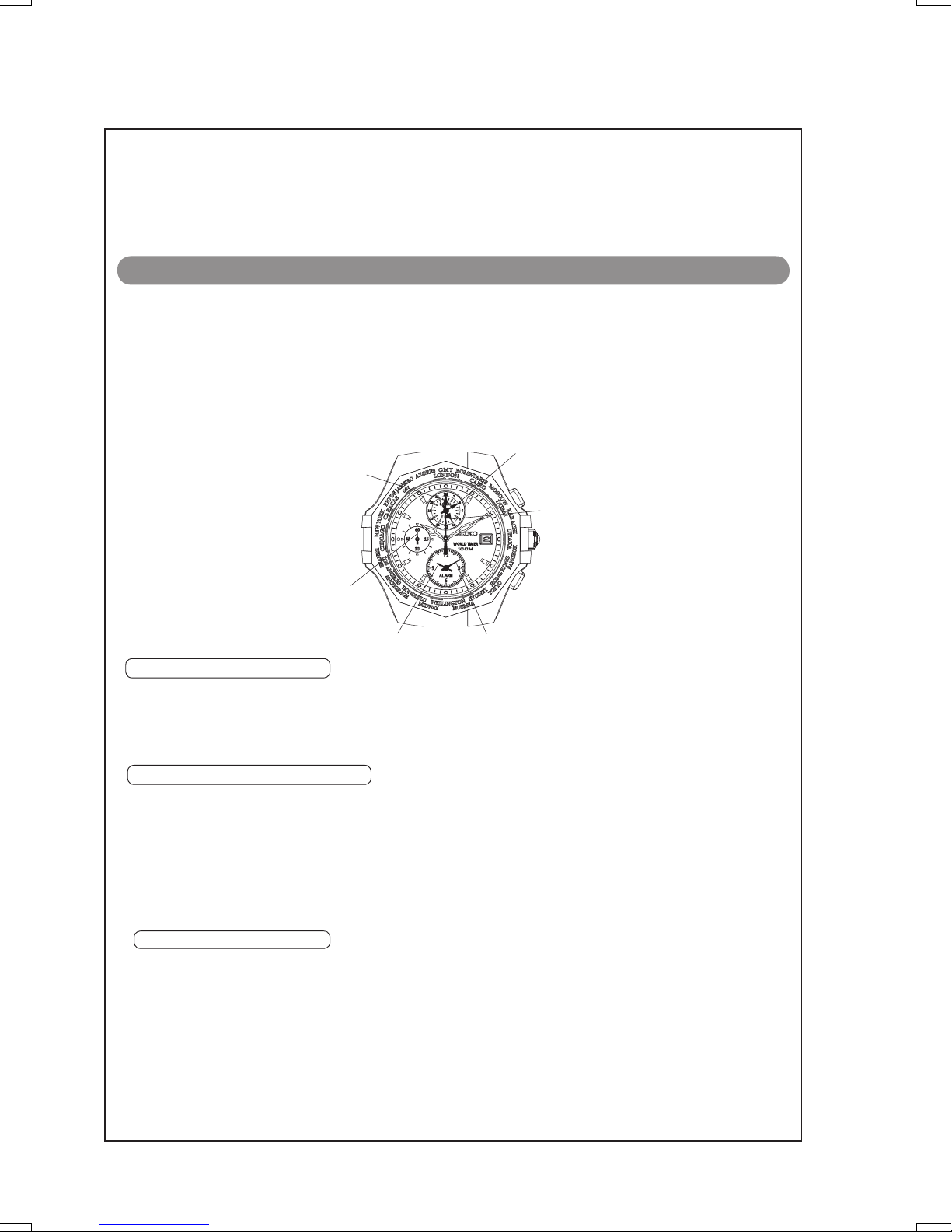
1. ALARM FUNCTION
• Apart from the main time, the time in the city selected by the city hand is displayed with
the designated WORLD TIME hands.
•The time in 24 cities is displayed in the 24-hour indication.
● Button operation (Crown position: Original position)
WORLD TIME city selection (turn clockwise)
WORLD TIME city selection (turn counterclockwise)
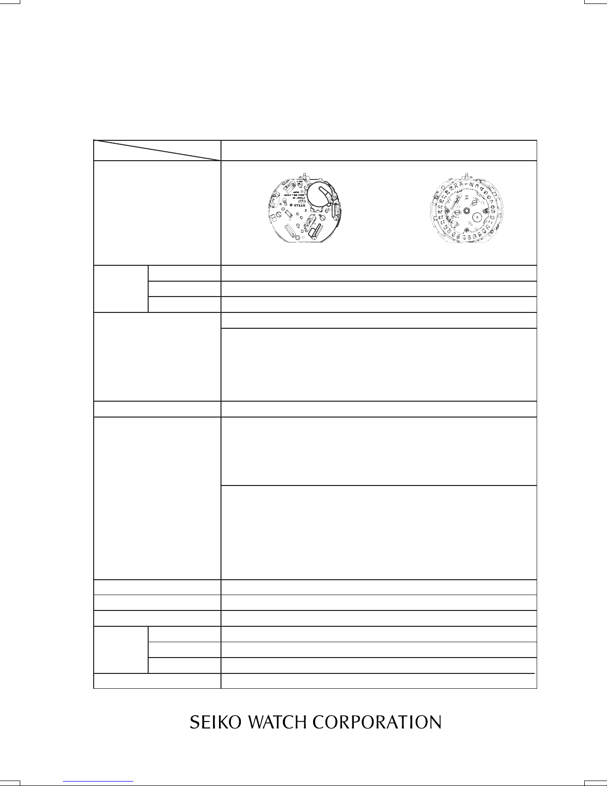
City hand
WORLD TIME minute hand
Button A
WORLD TIME hour hand
Crown
Button B
ALARM minute handALARM hour hand
Small second hand
Cal. 5T82A
WORLD TIME
3. SYSTEM RESET
When an abnormal display appears, reset the built-in integrated circuit. The watch will resume
its normal operation.
● Button operation (Crown position: Second click)
Press and hold buttons A and B at the same time for longer than 2 seconds.

REMARKS ON REPAIRING CAL. 5T82A
3/26
After installing the battery, reset the built-in integrated circuit, and then set the time and adjust
the ALARM and WORLD TIME hand positions following the procedure below.
II. NECESSARY PROCEDURE AFTER BATTERY CHANGE
Pull out to the 2nd click when the small second hand is at the
12 o’ clock position.
Turn to set the main time.
* Check that AM/PM is correctly set.
Pull out the crown to the 2nd click.
Press and hold both buttons A and B at the same time for longer than 2 seconds.
Push back in to the normal position in accordance with a time signal.
Press Button B to set the ALARM hands to the current time.
Press Button B to set the city hand to point to the city of
which you know the current time.
Press Button A for longer than 2 seconds.
The WORLD TIME hand turns a full circle.
Press Button B to set the WORLD TIME hands to the time
of the city you have selected by the city hand.
Press Button A for longer than 2 seconds.
The city hand turns a full circle.
Button B
Crown
Crown
Systen Reset
Crown
Note*
Note* Pressing Button A for longer than 2 seconds here will allow you to resume the procedure again
as indicated by the arrow if neccessary.
Button A
Button B
Button A
Button B

Cal. 5T82A
PARTS CATALOGUE
4/26
Lubricating of some parts is shown in “II. REMARKS ON DISASSEMBLING AND REASSEMBLING.”
0027 973
Pin for date dial guard
1
0808 580
Date dial guard
2
0878 526
Date dial
3
0962 580
Intermediate wheel for calendar correction
4
0737 580
Date corrector setting wheel
5
0278 581
Hour wheel for WORLD TIME
24-hour indication
7
0271 588
Hour wheel
9
0802 580
Date driving wheel
6
0271 583
Hour wheel for alarm
8
Disassembling procedures Figs. : 1 59
Reassembling procedures Figs. : 59 1
Remarks on removing the winding stem
To remove the winding stem when taking
out the movement from the case or while
disassembling the par ts during repair
work, be sure to pull out the crown to the
first click, and then, remove the winding
stem while pushing the setting lever.
* For the type of oil and quantity of lubrication, refer to the following TECHNICAL GUIDE section.

PARTS CATALOGUE Cal. 5T82A
Lubricating of some parts is shown in "II. REMARKS ON DISASSEMBLING AND REASSEMBLING."
4259 509
Anti magnetic shield plate B
10
3013 250 (SR927W)
Battery
11
0022 230
Battery clamp screw
12
4225 547
Battery clamp
13
0022 459
Circuit block cover screw
14
4457 980
Circuit block cover
15
4224 514
Conducting plate
16
0396 580
Friction spring for second counting
17
4000 619
Circuit block
18
4589 801
Piezoelecric element
*The piezoelectric element is
adhered to the case back.
0022 459
Circuit block cover screw
( 3 pcs.)
0022 230
Battery clamp screw (3 pcs.)
5/26

Cal. 5T82A
PARTS CATALOGUE
Lubricating of some parts is shown in "II. REMARKS ON DISASSEMBLING AND REASSEMBLING."
4246 700
Buzzer lead terminal
19
0240 580
Small second wheel
23
0701 580
Fifth wheel & pinion
26
0950 590
Intermediate wheel for WORLD TIME
28
0885 594
First intermediate wheel for city setting
30
0270 582
Center minute wheel for WORLD TIME
32
4283 581
Spacer for center wheel & pinion
34
0885 595
Second intermediate wheel for city setting
35
4146 710
Step rotor
37
4146 710
WORLD TIME rotor
39
4146 710
Rotor for city setting
40
4270 710
Battery connection (–)
20
0027 974
Pin for train wheel bridge
21
0125 509
Train wheel bridge
22
0888 582
City setting wheel
24
0241 583
Fourth wheel & pinion
25
0231 580
Third wheel & pinion
27
0950 590
Intermediate wheel for ALARM
29
0270 582
Center minute wheel for ALARM
31
0261 580
Minute wheel
33
4450 703
Switch lever A
36
4146 710
ALARM rotor
38
0383 592
Setting lever
41
0384 582
Yoke
42
0351 583
Winding stem
43
6/26

PARTS CATALOGUE Cal. 5T82A
7/26
Lubricating of some parts is shown in “II. REMARKS ON DISASSEMBLING AND REASSEMBLING.”
0281 580
Setting wheel
44
0264 580
Minute wheel for WORLD TIME
24-hour indication
45
0261 582
Minute wheel for ALARM
46
0282 585
Clutch wheel
47
0221 583
Center wheel and pinion
48
4002 700
Coil block (A)
49
0391 591
Train wheel setting lever
51
4239 710
Rotor stator
52
4002 711
Coil block for ALARM
55
4239 712
Rotor stator for ALARM
57
4450 701
Switch lever B
58
4002 700
Coil block for city setting
50
4239 711
Rotor stator for city setting
53
4002 711
Coil block for WORLD TIME
54
4239 713
Rotor stator for WORLD TIME
56
0100 559
Main plate
59

Cal. 5T82A
PARTS CATALOGUE
8/26
The correct parts for the followings are determined based on the design of cases. Check the case
number, and refer to "Watch Parts Catalogue CD-ROM" to choose corresponding parts.
✳ Holding ring for dial (0866 651)
3 Date dial (0878 526)
43 Winding stem (0351 583)
• Point of distinction
Refer to the illustrations below to see the difference between those two types of pins.
1 Pin for date dial guard
0027 973
22 Pin for train wheel bridge
0027 974

Cal. 5T82A T ECHNICA L GUIDE
9/26
No.
PROCESS
ILLUSTRATIONS AND SPECIAL INSTRUCTIONS ETC.
Assembling the
switching unit and
wheels
59Set the main plate.
Lubricate the lower
pivots of the rotors.
Lubricate the
contact area
between the small
second wheel and
main plate.
Lubricate the point
of engagement of
the switch lever B.
Lubricate the axis of
the switch lever B.
<59> Set the main plate.
Lubricate the contact area between the small
second wheel and main plate: Moebius F or AO-2
<Amount of lubricant
Refer to the illustrations below to see the right
amount of lubricant.
(a) (b) (c)
(a) Overlubricated
(b) Appropriately lubricated
(c) Underlubricated
Appropriate amount(Stone)
Appropriate amount(Convex part)
Appropriate amountS-6
Lubricate the point of engagement of
the switch lever B: S-6
Lubricate the axis of the switch lever B: Moebius V or AO-3
Lubricate the lower pivots of the rotors: Moebius F or AO-2

Cal. 5T82A T ECHNICA L GUIDE
10/26
NO.
PROCESS
ILLUSTRATIONS AND SPECIAL INSTRUCTIONS ETC.
58 Set the switch lever B.
56 Set the rotor stator for
WORLD TIME
Lubricate the axis of the
setting wheel.
57 Set the rotor stator for
ALARM.
55, 54
Set the coil blocks for
ALARM and WORLD
TIME.
53, 52
Set the rotor stator for
city setting, and rotor
stator.
51 Set the train wheel
setting lever.
50, 49
Set the coil block for
city setting and the coil
block (A).
56
Set the rotor stator for
WORLD TIME.
53, 52
Rotor stator for city setting
Discrimination number
Set the rotor stator.
Discrimination number0
50, 49Set the coil block for city setting and the coil block (A).
Coil resistance: 2.10 K2.70 K
58
Set the switch lever B.
55, 54
Set the coil blocks for ALARM and WORLD TIME.
Coil resistance: 1.80 K2.40 K
57
Set the rotor stator for ALARM.
Lubricate the axis of the setting
wheel: Moebius V or AO-3
51
Set the train wheel setting lever.

C al. 5 T8 2 A T E C HN IC A L GU I DE
11/26
NO.
PROCESS
ILLUSTRATIONS AND SPECIAL INSTRUCTIONS ETC.
48
Set the center wheel &
pinion and lubricate its
convex part and inner
edge of the ring.
47 Set the clutch wheel.
46 Set the minute wheel for
ALARM.
45
Set the minute wheel for
WORLD TIME 24-hour
indication.
44 Set the setting wheel.
43 Set and lubricate the
winding stem.
42 Set the yoke.
41 Set the setting lever.
40, 39
Set the rotor for city
setting and the WORLD
TIME rotor.
38, 37 Set the ALARM rotor and
step rotor.
White
8
40, 39, 38, 37Set the rotor for city setting, WORLD TIME rotor, ALARM rotor and step rotor.
48
Set the center wheel & pinion and lubricate as
illustrated below.2 points: Moebius AII or
AO-3
45Set the minute wheel
for WORLD TIME 24-hour
indication.
47Set the clutch wheel.
44Set the setting wheel.
43Set and lubricate the winding stem:
Lubricate the entire profile of the winding stem with
Moebius V or AO-3.
41Set the setting lever.
Crown at the normal position.
42Set the yoke.
Remember to install the winding stem before
setting the yoke. Otherwise the spring of yoke
will lift the clutch wheel upward.
The reset spring of the yoke is easily deformable.
Handle it with extra care as deformation of the
spring can cause reset failure as well as mode
change malfunction.
46Set the minute wheel for ALARM.
6
6

Cal. 7T82A T ECHNICA L GUIDE
12/26
No.
PROCESS
ILLUSTRATIONS AND SPECIAL INSTRUCTIONS ETC.
Lubricate the switching
unit.
Point of contact
between the train wheel
setting lever and yoke.
Point of contact in
the tail portion of the
yoke.
Point of contact
between the yoke and
setting lever.
Axis of the setting
lever
Axis of the switch
lever A
Point of engagement
of the switch lever A
36
Set the switch lever A.
Lubricate the point of contact between the train wheel
setting lever and yoke. (Lubricate the two points with
either Moebius V or AO-3.
Lubricate the axis of the switch lever A. (:
S-6
<36> Set the switch lever A.
Lubricate the point of contact in the tail portion of
the yoke. (: Moebius V or AO-3
Lubricate the point of contact between the yoke
and setting lever. (: S-6
Lubricate the axis of the setting lever.(: S-6
Lubricate the point of engagement of the switch
lever A. (: S-6

C al. 5 T8 2 A T E C HN IC A L GU I DE
13/26
NO.
PROCESS
ILLUSTRATIONS AND SPECIAL INSTRUCTIONS ETC.
35
Set the second
intermediate wheel for
city setting.
34 Set the spacer for center
wheel & pinion.
33 Set the minute wheel.
32, 31
Set the center minute
wheel for WORLD TIME
and center minute wheel
for ALARM.
Lubricate the point of
contact of the spacer for
center wheel & pinion.
30 Set the first intermediate
wheel for city setting.
29Set the intermediate
wheel for ALARM.
28Set the intermediate wheel
for WORLD TIME.
27, 26
Set the fifth wheel and
pinion and third wheel
and pinion.
25Set the fourth wheel and
pinion.
24Set and lubricate the city
setting wheel.
23Set the small second
wheel.
Center minute wheel for
WORLD TIME
30Set the first intermediate wheel for city setting.
27, 26Set the fifth wheel and pinion and
third wheel and pinion.
34Set the spacer for center wheel & pinion.
33Set the minute wheel.
31, 32
Set the center minute wheel for
WORLD TIME and center minute
wheel for ALARM.
25Set the fourth wheel & pinion.
24
Set and lubricate the city setting wheel as illustrated above.
Lubricate the point of contact of the spacer for center wheel &
pinion: Moebius A or AO-3.
23Set the small second wheel.
29Set the intermediate wheel
for ALARM.
White
35Set the second intermediate wheel
for cit
y
settin
g
.
Lubricate the point of contact of the
spacer for center wheel & pinion
Moebius A or AO-3
Dark green
White
28Set the intermediate wheel
for WORLD TIME.

Cal. 5T82A T ECHNICA L GUIDE
14/26
No.
PROCESS
ILLUSTRATIONS AND SPECIAL INSTRUCTIONS ETC.
22Set the train wheel
bridge.
21Set the pin for train
wheel bridge.
20Set the battery
connection (-)
Lubricate the upper
pivots of the rotor for
city setting, WORLD
TIME rotor, and
ALARM rotor and
step rotor.
19 Set the buzzer lead
terminal.
1
Lubricate the upper
pivots of the minute
wheel, center minute
wheel for ALARM,
city setting wheel,
center minute wheel
for WORLD TIME
and small second
wheel.
<22> Set the train wheel bridge.
Minute wheel
*1The upper pivot of theminute wheel for WORLD TIME should be additionally lubricated.
5 points to be lubricated as illustrated above.
Other portions
Upper pivot of the rotor
Lubricate the upper pivots of the minute wheel, center minute wheel for ALARM, city setting wheel, minute wheel
for WORLD TIME and small second wheel: Moebius F or AO-2.
<21> Set the pin for train wheel bridge.
Turn the pin 90-degree clockwise to
fix it using a screwdriver.
Make sure that the pin is put in the
correct direction.
Never turn the pin more than 90
degrees.
Lubricate the upper pivots of the rotor for city setting, WORLD TIME rotor, and ALARM rotor and
step rotorMoebius F or AO-2
Lubricate the upper pivot of each rotor (at four points) illustrated below.
<19> Set the buzzer lead terminal.
<20> Set the battery connection (-).

Cal. 5T82A T ECHNICA L GUIDE
15/26
NO.
PROCESS
ILLUSTRATIONS AND SPECIAL INSTRUCTIONS ETC.
Assembling the
circuit unit
18Set the circuit block.
17
Set the friction
spring for second
counting.
16Set the conducting
plate.
15Set the circuit block
cover.
Securely engage the
four hooks.
14Tighten the circuit
block cover screws.
3 positions
16Set the conducting plate.
14
Tighten the circuit block cover screws (3 positions.)
18Set the circuit block.
Make sure that the circuit block is securely engaged with the two
guide pins of the train wheel bridge.
Take care so as not to deform these parts while setting the circuit
block.
Remarks on installing the circuit block cover. (hooking portions)
• Take care so as not to deform the rotor stator or coil block.
• Make sure that the circuit block cover is correctly aligned with the two pins of the train wheel bridge.
* Inaccurate alignment of the circuit block cover can cause malfunction of the yoke, resulting in defects
of date correcting function.
• The hook of the circuit block cover is easily disengaged. Make sure that it is securely engaged with
the pins all the way in at the four locations.
• Unhook the circuit block cover from a side angle using a pair of tweezers or a screwdriver while
gently pressing it down.
• The cond uctive spr ing of the circuit block cover is easily deformable. Handle it with
care so as n ot to def or m it .
17Set the friction spring for
second counting.
15Set the circuit block cover.
Securely engage the four hooks.

Cal. 5T82A T ECHNICA L GUIDE
16/26
NO.
PROCESS
ILLUSTRATIONS AND SPECIAL INSTRUCTIONS ETC.
12 Set the battery
clamp.
11
Tighten the battery
clamp screws.
(3 positions)
Measure the
current
consumption.
11Tighten the battery clamp screws. (3 positions)
12Set the battery clamp.

C al. 5 T8 2 A T E C HN IC A L GU I DE
17/26
No.
PROCESS
ILLUSTRATIONS AND SPECIAL INSTRUCTIONS ETC.
As semblin g the
calendar unit.
9 Set the hour wheel.
8Set the hour wheel
for ALARM.
7
Set the Hour wheel
for WORLD TIME
24-hour indication.
6 Set the date driving
wheel.
5
Set the date
corrector setting
wheel.
4
Set the intermediate
wheel for calendar
correction.
Lubricate the point
of contact between
the date dial and
main plate.
3Set the date dial.
The hour wheel is made of plastic.
Make sure that the gear teeth are
properly engaged when setting the
hour wheel.
<3> Set the date wheel.
The number of gear teeth is 28.
<9> Set the hour wheel.
<6> Set the date driving wheel.
<8> Set the hour wheel for ALARM.
<7>
Set the Hour wheel for WORLD TIME 24-hour indication.
<5> Set the date corrector setting wheel.
<4> Set the intermediate wheel for calendar correction.
Lubricate the point of contact between the date
dial and main
p
lateMoebius A or AO-3
The number of gear teeth is 48.

Cal. 5T82A T ECHNICA L GUIDE
18/26
No.
PROCESS
ILLUSTRATIONS AND SPECIAL INSTRUCTIONS ETC.
2 Set the date dial
guard.
Set the jumper.
1
Set the pins for date
dial guard.
(2 positions)
Lubricate the points
of contact between:
Date dial and
date jumper.
Main plate and
date jumper.
Date dial guard and
date jumper.
<2> Set the date dial guard.
Lubricating points of the calendar wheels: contact points between
Date dial and date jumperMoebius F or AO-2
Main plate and date jumper: Moebius F or AO-2
Date dial guard and date jumperMoebius F or AO-2
<1> Set the date dial guard.2 positions
Turn the pin 90-degree clockwise to fix itusing a screwdriver.
Never turn the pin more than 90 degrees.

Cal. 5T82A TEC HNICA L GUIDE
19/26
No.
PROCESS
SPECIFICATIONS (QUALITY SPECIFICATIONS,
HANDLING METHODS ETC.)
ILLUSTRATIONS AND SPECIAL INSTRUCTIONS ETC.
Assemblin g the
case
11Set the battery.Pay extra attention so as not to short-circuit the battery.
A
Connect the AC comp onent to the ci rc uit blo ck co ver until a
short circu it occurs to reset the integrated circuit.
Set the movement.Do not press the date dial down when handling the movement.
Be careful so as not to deform the conducting spring of the movement.
Check that the date
changes correctly. Make sure that the date changes smoothly without dragging.
Set the holding ring
for dial.
When installing the holding ring for dial, be careful so as not to unhook
it.
Set the dial.
Preparation for
installing the hands Follow the instructions below before installing the hands.
It is necessary to adjust the backlash in a certain direction in order to
ensure the proper hand positions before installing the hands.
Activate the city hand in the hand adjustment mode.
Press and hold Button A for 3 seconds or longer with the crown at the
second click position.
Adjust the backlash by turning the city hand, which is located at the
center, clockwise.
11Set the battery.
Install the battery in the direction shown by the arrow in the illustration below. Installing the
battery from any other angle may result in bending or deforming the battery connection (-).
System Reset
Connect the AC component to the circuit block cover until a short circuit occurs to reset the
integrated circuit.
Be careful so as not to deform the
conducting spring while installing the
battery or movement.

Cal. 5T82A T ECHNICA L GUIDE
20/26
No.
PROCESS
SPECIFICATIONS (QUALITY SPECIFICATIONS,
HANDLING METHODS ETC.)
ILLUSTRATIONS AND SPECIAL INSTRUCTIONS ETC.
(12 o’clock position)
Set the ORLD TIME hour
hand.
Set the ORLD TIME
minute hand.
(9 o’clock position)
Set the small second hand.
Check the hand position and
hand installation height.
(6 o’clock position)
Set the ALARM hour hand.
Set the ALARM minute hand.
Check the hand position and
hand installation height.
(Center)
Set the hour hand.
Set the minute hand.
Check the hand position and
hand installation height.
Set the city hand.
Check the hand position and
hand installation height.
T82AWORLD TIME
WORLD TIME hour hand
&
WORLD TIME minute hand
Small second hand
ALARM hour hand
&
ALARM minute hand
City hand
Button B
CROWN
Button A
Table of contents
Other Seiko Watch manuals

Seiko
Seiko ANALOGUE QUARTZ SOLAR V145 User manual

Seiko
Seiko VD 57 User manual

Seiko
Seiko 5R86 User manual

Seiko
Seiko ASTRON 8X42 GPS SOLAR User manual

Seiko
Seiko Presage SPB305J User manual

Seiko
Seiko SSB125P1 User manual

Seiko
Seiko Cal. 4R15 User manual

Seiko
Seiko 5J32A Installer manual

Seiko
Seiko Credor 6870 User manual

Seiko
Seiko SSB261P1 User manual

Seiko
Seiko PSZ471P1 User manual

Seiko
Seiko ASTRON 8X53 GPS SOLAR User manual

Seiko
Seiko H021 User manual

Seiko
Seiko M-6 User manual

Seiko
Seiko Cal. V175 User manual

Seiko
Seiko Conceptual S23158J User manual

Seiko
Seiko 6A32 User manual

Seiko
Seiko 4T53 User manual

Seiko
Seiko Spectrum SVRD001 G510 User manual

Seiko
Seiko 6S37 User manual