Seiko V137A User manual

PARTS LIST /TECHNICAL GUIDE
ANALOGUE SOLAR Cal. V137A
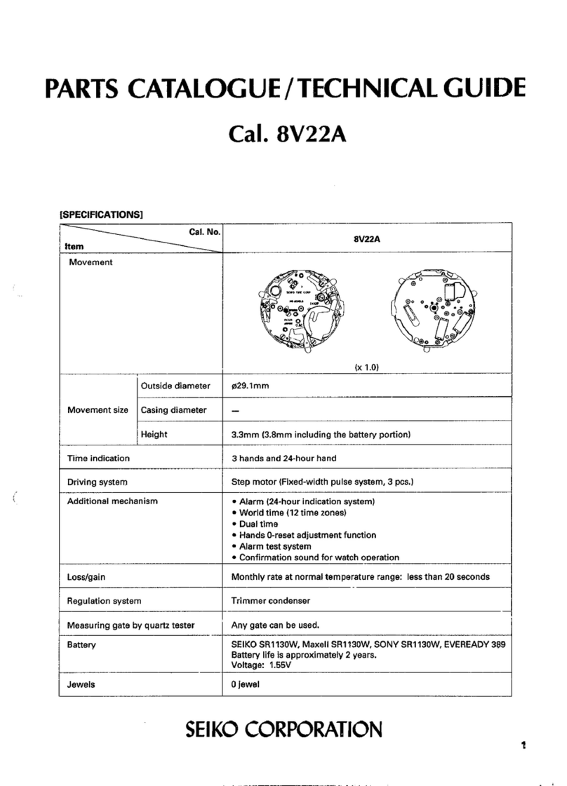
[SPECIFICATIONS]
1/18
Item Cal. No. V137A
Power reserve
Driving system
Additional function
Crown operation
Loss/Gain
Regulation system
Number of jewels
Normal position
1st click position
Current consumption
Gate time for rate measurement
Power
supply
Motion of the second hand
Coil resistance
Power generator
Rechargeable battery
Operating voltage range
2nd click position
One-second intervals
Stepping motor 1 piece (Load compensated driving pulse type)
Diameter: Outside 18.5 mm
17.5 mm (between 3 o’clock and
9 o’clock )
Casing 18.1 mm
Height: 2.6 mm
• Energy depletion forewarning function (The second hand moves at two-second
intervals.)
• Overcharge prevention function
• Electronic circuit reset function
• Second hand stop function
• Date calendar
• Instant setting device for date calendar
Free
Time setting
Monthly rate:less than 15 seconds (worn on the wrist at temperature range
between 5 to 35 degrees Centigrade)
Use 10-second gate
Nil
Solar power generation system
Movement: less than 0.75 µA
Circuit block: less than 0.30 µA
Coil block: 1.60-2.20 kΩ
MT621 Manganese titanium lithium rechargeable battery
0.90V - 2.20V
From full charge to stoppage: Approximately 6 months
2 jewels
Date setting (clockwise)
3 hands
(hour, minute and small second
hands)

Cal. V137A
PARTS LIST
2/18
FEATURES
Cal. V137A is an analogue watch with a solar power generation system.
l Solar power generation system
The watch operates while charging electricity by converting light received on the dial to
electrical energy. It lasts for 6 months after full charge.
l Energy depletion forewarning function
When the energy stored in the rechargeable battery is reduced to an extremely low level, the
second hand starts moving at 2-second intervals instead of the normal 1-second intervals.
l Guideline of charging time
Environment/Light source Illumination
(lux)
Time required
for full charge
Time required
for steady
operation
Time to charge
1 day of power
General offices/ Fluorescent
Light
700 -16 hours 110 minutes
30W 20cm/Fluorescent light 3,000 90 hours 4 hours 30 minutes
30W 3cm/ Fluorescent light 10,000 30 hours 1.2 hours 8 minutes
Cloudy weather/Sunlight 10,000 30 hours 1.2 hours 8 minutes
Fair weather/Sunlight 100,000 10 hours 0.1 hours 1 minutes
The above table provides only a general guideline.
It is recommended that the watch be charged for as long as the charging time according to the
column "Time required for steady operation" in this table in order to assure the stable movement
of the watch.
l Caution for charging
When charging the watch, do not place it too close to a photo flash light, spotlight, incandescent
light or other light sources as the watch temperature will become extremely high, causing damage
to the parts inside the watch.
When exposing the watch to sunlight for recharging, do not leave it on the dashboard of a car, etc.
for a long time, as the increase of watch temperature to an extremely high level can damage watch
parts or cause malfunctions.
While charging the watch, make sure the watch temperature does not exceed 60 °C.

Order of disassembly: 1 34
Order of assembly: 34 1
1 HOUR, MINUTE
AND SECOND
HANDS
2 DIAL
3 DIAL SHEET
8700 ***
4 SOLAR CELL
4025 562
8 CASE RING
MOVEMENT
5 HOLDING RING
FOR DIAL
0866***
6 DIAL WASHER
0491 735
7 CONTACT POINT
SPRING FOR SOLAR
CELL (3 PCS.)
4246 529
9 DATE DIAL GUARD
0808 891
10 DATE DIAL
0878***
11 DATE JUMPER
0810 890
12 HOUR WHEEL
0271 647
13 DATE DRIVING
WHEEL
0802 891
Types of oil
AO-3
AO-2
Oil quantity
Small quantity
Normal quantity
Liberal quantity
PARTS LIST Cal. V137A
3/18
Please see the remarks on the following pages.

14 RECHARGEABLE BATTERY
BLOCK
3026 24X
15 CIRCUIT BLOCK
COVER SCREW
(3PCS.)
0022 247
16 CIRCUIT BLOCK
COVER
4461 548
17 CIRCUIT BLOCK
4000 775
Cal. V137A
PARTS LIST
4/18
Please see the remarks on the following pages.

18 TRAIN WHEEL BRIDGE
0125 517
19 FOURTH WHEEL AND
PINION
0241 173
20 THIRD WHEEL AND
PINION
0231 904
23 MINUTE WHEEL
0261 904
21 FIFTH WHEEL AND PINION
0701 904
22 STEP ROTOR
4146 907
24 TRAIN WHEEL
SETTING LEVER
0391 890
25 SETTING LEVER
0383 891
27 SETTING WHEEL
0281 904
26 YOKE
0384 890
28 SETTING STEM
0351 892
29 CLUTCH WHEEL
0282 890
30 DATE CORRECTOR WHEEL
0806 890
31 COIL BLOCK
4002 543
32 ROTOR STATOR
4239 549
33 CENTER WHEEL
AND PINION
0221 607
34 MAIN PLATE
0100 605
PARTS LIST Cal. V137A
5/18
Please see the remarks on the following pages.

Cal. V137A
PARTS LIST
6/18
l
How to find the correct parts, if not determined by 4 digit caliber number
Following parts are determined based on the design of watches, such as hands height, dial color,
and design of cases. Please refer to the SEIKO WATCH PARTS CATALOGUE in order to choose
the corresponding parts.
5 HOLDING RING FOR DIAL 0866 ***
10 DATE DIAL 0878 ***
28
SETTING STEM 0351 892
l
Other parts to pay attention to:
2 DIAL
3 DIAL SHEET
DIAL SHEET is used or not used depending on the design of watches.
Whether it is used or not can be judged from parts number of the DIAL.
Model with DIAL SHEET: The 9th digit of Dial number is “T.“
Example: V1370AA0TS14
Model without DIAL SHEET: The 9th digit of Dial number is “X.“
Example: V1370AA0XS14
l
Rotation movement:
The RECHARGEABLE BATTERY BLOCK is not assembled in the replacement movement for Cal.V137A.

PARTS LIST Cal. V137A
7/18
lTools and consumables required for disassembling/reassembling
•Movement holder
UNIVERSAL MOVEMENT HOLDER (S-682)
• Watch oils
SEIKO watch oils (AO-3 and AO-2)
AO-3 AO-2

4 SOLAR CELL
5 HOLDING RING FOR DIAL
* It is not necessary to separate the SOLAR CELL and the HOLDING RING FOR DIAL except in the case
that a part needs to be replaced.
• Disassembling and Reassembling of HOLDING RING FOR
DIAL
<Disassembling>
1. The HOLDING RING FOR DIAL is fixed to the movement by
the hooking portion at 12 o’clock and 6 o’clock positions.
2. Insert the tip of a screwdriver into the gap between the
hooking portion and main plate to release the hooking
portion from the main plate as shown with the arrow mark
in the illustration.
TECHNICAL GUIDE Cal. V137A
8/18
REMARKS ON DISASSEMBLING AND REASSEMBLING
REMARKS ON DISASSEMBLING AND REASSEMBLING THE MOVEMENT
Set the notched portions of the DIAL SHEET to the guide post
(4 posts) of the HOLDING RING FOR DIAL, and check that the
DIAL SHEET is fixed in position.
• Howtoinstall
2 DIAL
• Howtoinstall
3 DIAL SHEET (Not used in some models)
Set the notched portions of the DIAL to the guide posts (4 posts)
of the HOLDING RING FOR DIAL, and check that the DIAL is
fixed in position.

<Reassembling>
1. Set the 2 hooking portions to 12 o’clock and 6 o’clock
positions as shown in the illustration.
2. Gently push the hooking portions of HOLDING RING
FOR DIAL so that they catch the main plate securely.
TECHNICAL GUIDE Cal. V137A
9/18
• DisassemblingandReassemblingofSOLARCELL
* Do not apply excessive force to the SOLAR CELL.
* Just like COIL BLOCK, SOLAR CELL gets damaged easily by static electricity. Be careful not
to get it magnetized, especially the part where it touches CONTACT POINT SPRING.
<Disassembling>
As there are 2 connection parts of the HOLDING RING FOR DIAL, release them side by side.
<Reassembling>
Set the SOLAR CELL to 2 guide posts, and assemble
it to the HOLDING RING FOR DIAL by gently pushing
the hooking positions of the SOLAR CELL as shown
by the arrow marks in the illustlation.

7 CONTACT POINT SPRING FOR SOLAR CELL
Set 3 pcs of CONTACT POINT SPRING FOR SOLAR CELL at the
correct position as shown in the illustration.
Note: While other solar movements normally use 2 pcs of
CONTACT POINT SPRING FOR SOLAR CELL, 3 pcs are used in
Cal. V137. The third piece is assembled to keep the metallic part
under the SOLAR CELL in positive potential in order to stabilize
the watch’s performance.
9 DATE DIAL GUARD
<Disassembling>
1. Lightly lift the A portion of the date dial guard with
tweezers to release it from the guide pin, and then move
it in the counterclockwise direction to put it on the guide
pin.
2. Release the B portion of the date dial guard in the same
way as described above.
3. Check that all the three hooking portions of the DATE
DIAL GUARD have come off from the MAIN PLATE, and
then remove the DATE DIAL GUARD.
<Reassembling>
1. Put the DATE DIAL GUARD on the MAIN PLATE so
that the A and B portions are over the guide pins, as
shown in the illustrations at right.
2. Move the portion D in the clockwise direction so that
it is caught under the MAIN PLATE.
3. Slightly move the portions C and E in the clockwise
direction alternately to set them under the MAIN
PLATE. Then, set the A and B portions to the guide
pins.
4. Check that the DATE DIAL GUARD is fixed securely to
the MAIN PLATE.
TECHNICAL GUIDE Cal. V137A
10/18
A PORTION
B PORTION
HOOKING PORTIONS
DATE DIAL
GUARD
GUIDE PIN
TWEEZERS
C PORTION
B PORTION PORTION D
E PORTION
A PORTION

<Lubrication>
Lubricate the contact point with DATE DIAL and the center pipe.
AO-3
14 RECHARGEABLE BATTERY BLOCK
<Reassembling>
Set the (-) lead terminal of the RECHARGEABLE BATTERY BLOCK to the correct positon as shown in
the illustration below, and check that the (-) lead terminal touches the conducting pin.
(-) LEAD TERMINAL CONDUCTING PIN
(-) LEAD TERMINAL
After reasssembling
TECHNICAL GUIDE Cal. V137A
11/18

16 CIRCUIT BLOCK COVER
<Disassembling>
1. Loosen the 3 CIRCUIT BLOCK COVER SCREWs.
2. Release the 3 hooking portions of the CIRCUIT
BLOCK COVER indicated by the arrows in the
illustration below.
B PART
A PART
SCREW
SCREW
SCREW
<Reassembling>
1. Set the 3 hooking portions of the CIRCUIT
BLOCK COVER and make sure it catch the
movement securely. In doing so, check if the
circuit block is set properly to guide posts “A”
and “B,” and reset it in position if necessary.
2. Tighten the 3 CIRCUIT BLOCK COVER SCREWs.
When tightening the screws, take care not to cut
the coil.
18 TRAIN WHEEL BRIDGE
<Reassembling>
Before setting the TRAIN WHEEL BRIDGE,
refer to the illustration to check the
setting position of the respective wheels.
Note: Take care if the TRAIN WHEEL BRIDGE
is set in a position since no screw is used to
secure it.
STEP ROTOR
FIFTH WHEEL
AND PINION
THIRD WHEEL
AND PINION
FORTH WHEEL
AND PINION
SETTING
WHEEL
MINUTE
WHEEL
<Lubrication>
Lubricate the pivots as shown in the illustration.
Be sure to lubricate the cotact point of TRAIN
WHEEL SETTING LEVER and SETTING LEVER.
STEP ROTOR
MINUTE WHEEL AO-3
AO-2
TECHNICAL GUIDE Cal. V137A
12/18

24 TRAIN WHEEL SETTING LEVER
25 SETTING LEVER
26 YOKE
YOKE
34 MAIN PLATE
SETTING LEVER
SETTING STEM
MINUTE WHEEL
TRAIN WHEEL
SETTING LEVER
28 SETTING STEM
AO-3
AO-2
<Reassembling>
Refer to the illustration to check the setting
position of the parts.
<Lubrication>
<Lubrication>
TECHNICAL GUIDE Cal. V137A
13/18

TECHNICAL GUIDE Cal. V137A
14/18
l
CHECKING THE ELECTRICAL CHARACTERISTICS
<Coil resistance>
31 COIL BLOCK between 1.60 and 2.20 kΩ
<How to measure the current consumption for the whole movement>
1) Remove 5 HOLDING RING FOR DIAL, 4 SOLAR CELL and 14 RECHARGEABLE BATTERY BLOCK
from the movement.
2) Connect the (-) probe and the (+) probe as shown in the illustration. Do not remove them until
measurement is finished.
* When measuring the current consumption using
the SEIKO digital multi-tester (S-860), use the
range of 40µA of SUPPLY V (=1.55V) & GATE
TIME (2S).
3) Wait until a stable measurement becomes available. It usually takes 30 seconds to a few minutes
for getting a stable measurement.
4) Make sure that the read value is less than 0.75µA.
REMARKS ON INSPECTION AND MEASUREMENT

TECHNICAL GUIDE Cal. V137A
15/18
* When measuring the current consumption using
the SEIKO digital multi-tester (S-860), use the
range of 40µA of SUPPLY V (=1.55V) & GATE
TIME (2S).
* Avoid exposing the CIRCUIT BLOCK to direct
light in order to obtain the correct measurement.
2) Wait until a stable measurement becomes available. It usually takes 30 seconds to a few minutes
for getting a stable measurement.
3) Make sure that the read value is less than 0.30µA.
Note:
In case the measurement of the current consumption for a whole movement exceeds the standard
value but the measurement for the circuit falls below the standard value, a problem in the gear train
mechanism is suspected. Please disassemble and overhaul the movement and measure the current
again.
C-MOS-IC
COIL OUTPUT TERMINAL
CRYSTAL OSCIL ATOR
<How to measure the current consumption for the CIRCUIT BLOCK alone>
1) Connect each probe to the appropriate (-) and (+) input terminal of 17 CIRCUIT BLOCK (please
refer to the "Structure of the CIRCUIT BLOCK" below).
[Structure of the CIRCUIT BLOCK]
INPUT TERMINAL (+)
INPUT TERMINAL (-)

TECHNICAL GUIDE Cal. V137A
16/18
l
CHECKING THE SOLAR POWER GENERATION SYSTEM
<How to check the solar power generation with the watch>
1)
Remove the RECHARGEABLE BATTERY UNIT from the watch.
2) Pull out the crown to the 2nd click position in order to reset the circuit.
3) Connect the (-) probe and (+) probe as illustrated.
* When measuring the voltage using the SEIKO digital
multi-tester (S-860), use the range of V.
4) Expose the watch to the light of a fluorescent lamp
(use the one with 15 to 20 watts) at a distance of 5 – 10
cm while connecting the probes to the watch.
5) Read the measurement and check if it exceeds 1.8 V.
FLUORESCENT LAMP
15 – 20 W
5 – 10 cm

TECHNICAL GUIDE Cal. V137A
17/18
Note: In case the measurement of the voltage for the watch does not achieve the standard value but
the measurement for the solar cell unit alone exceeds the standard value, a problem in the electrical
conductivity between the solar cell unit and the movement is suspected. Inspect the electrical
conductivity, especially at the CONTACT SPRING FOR SOLAR CELL, and check the solar power
generation system again.
<How to check the solar power generation with the SOLAR CELL alone>
1) Set the SOLAR CELL to the HOLDING RING FOR DIAL.
2) Connect the tester as the below illustration.
* When measuring the voltage using the SEIKO digital
multi-tester (S-860), use the range of V.
2) Expose the SOLAR CELL to the light of a fluorescent lamp (use the one with 15 to 20 watts) at a
distance of 5 – 10 cm while connecting the probes to the solar cell unit.
3) Read the measurement and check if it exceeds 1.8 V.
5 – 10 cm
FLUORESCENT LAMP
15 – 20 W

TECHNICAL GUIDE Cal. V137A
18/18
l
CHECKING THE RECHARGING FUNCTION
In order to check the recharging function, measure the voltage of the rechargeable battery before and
after recharging. If the voltage increases to a certain extent, it shows that the recharging function is
working properly.
Copyright©2013 by
1) Connect the (-) probe and the (+) probe as illustrated.
2) Measure the voltage of the rechargeable battery
before recharging.
3) Recharge the watch by placing it at a distance of 5 – 10 cm
under the fluorescent lamp of 15 to 20 watts for 30 minutes.
FLUORESCENT LAMP
15 – 20 W
5 – 10 cm
4) Measure the voltage again while keeping the watch
exposed to the light.
5) Compare the difference of the voltage before and
after recharging.
Refer to the table below for the criteria of the
inspection.
FLUORESCENT LAMP
5 – 10 cm
0.50V - 1.00V
Results after recharging and criteria for checking the function
Recharging function works fine
The voltage
before recharging
1.01V - 1.30V
Less than 1.09V
Increased by 0.03V or more
More than 1.10V
Not increased or increased
but not more than by 0.03V
The battery needs to be inspected and
replaced if necessary
Table - criteria recharging function Cal. V137A
Table of contents
Other Seiko Watch manuals

Seiko
Seiko V072 User manual

Seiko
Seiko 4205B Quick start guide

Seiko
Seiko Map Meter Instruction and safety manual

Seiko
Seiko SSB261P1 User manual

Seiko
Seiko 6M15A Installer manual

Seiko
Seiko Prospex SNE577P User manual

Seiko
Seiko 7T52 User manual

Seiko
Seiko 8V36 User manual

Seiko
Seiko Alarm Chrono 7T32 Operating manual

Seiko
Seiko Conceptual SUR377P User manual

Seiko
Seiko Y187 User manual

Seiko
Seiko SSE017J9 User manual

Seiko
Seiko 0664A Quick start guide

Seiko
Seiko KINETIC 7D48 User manual

Seiko
Seiko S056 User manual

Seiko
Seiko 4F56 User manual

Seiko
Seiko 7K52A Installer manual

Seiko
Seiko SPC244P1 User manual

Seiko
Seiko M-3 User manual

Seiko
Seiko SKY671P1 User manual