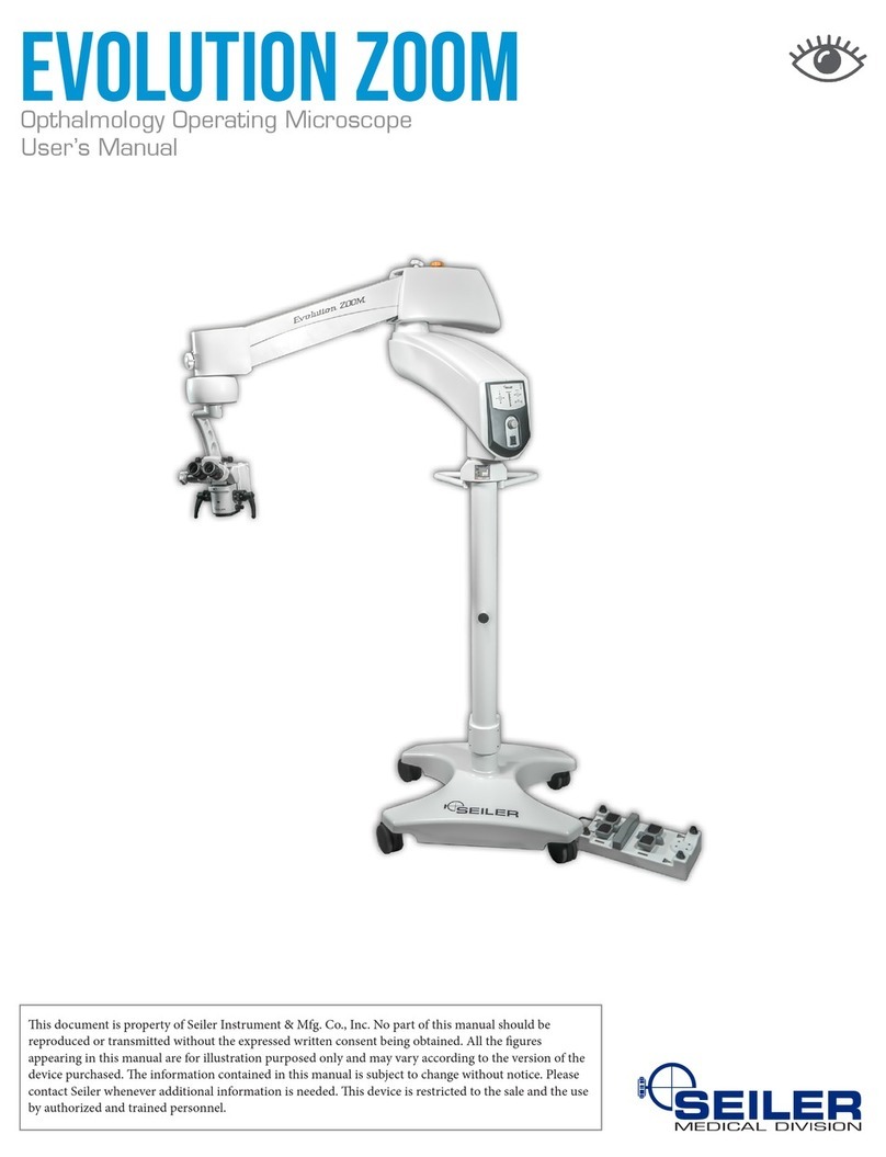
Seiler Evolution Zoom User manual

OPERATING MICROSCOPE
OWNERÕ S MANUAL

We are here to serve you!
If you have any questions regarding Seiler’s products or services,
please feel free to contact us.
: 800.489.2282
: 314.968.2282
: 314.968.3601
: www.seilerinst.com
• Division Manager
Dane Carlson
• Corporate Accounts/Marketing
Nicole Rasch
• Technical Product Information
Tony Leise
• Accounts/Tracking/Bulbs
Sandy Jeremich
(
(
2
*
8

CONTENTS
1. INTRODUCTION 2
Dear customer, thank you for choosing this product. 2
2. COMPONENTS 3
Structural 3
Illumination: 3
Control 3
Optical Module 3
Control Pedal 4
3. ASSEMBLY 8
Unpacking 8
Column, Control Box and Pantographic Arm 9
Optical Module 10
Electrical Connections 11
4. USING THE MICROSCOPE 12
Moving the Optical Module 12
Switching on the unit 15
Diopter Adjustment. 16
Interpupillary Distance Adjustment 16
Adjusting the Focus, Diopters and Interpupillary Distance 17
Using the XY system (optional) 19
Using the Inclinable Binocular 20
Ultra Violet (UV) Filter 20
5. MAINTENANCE, HANDLING AND HYGIENE 21
When the bulb burns out during use 21
Changing the bulb 22
Changing the fuses 23
General cleaning 23
Cleaning the lenses 23
Control Items Handling and Hygiene 24
Discard 25
6. TECHNICAL DETAILS 26
General Details 26
Electrical Details 26
Optical Details 26
7. ACCESSORIES 27
Beam Splitter 27
Camera Adapter 27
Video Camera 27
Digital Photographic Camera Adapter 27
Second Observer Accessory 27
Image Inverter 27
XY System 27
Multifunction Pedal 27
Binocular Head 27
Zoom System 27
Filters 27
8. WARRANTY 27

Seiler has developed this device in due accordance with global quality requirements, giving priority to safety,
electromagnetic compatibility and failure management, thereby establishing the Seiler Microscopes Evolution Zoom
as a highly safe, reliable and robust device. The main quality standards employed were based upon the standards set out
below:
DESIGN STANDARDS
• IEC60601-1:1988-MedicalElectricalEquipment,Part1-GeneralRequirementsforSafety
• ENIEC60601-1-2:2001MedicalDevices-EMCRequirements
• EN55011:1991-RadiatedandConductedEmission(Class1,GroupA)
• IEC61000-4-2:1995(ElectrostaticDischarge)
• IEC801-3:1984(RadiatedElectromagneticField)
• IEC61000-4-4:1995(ElectricalFastTransient/Burst)
• IEC61000-4-5:1995(ElectricalSurge)
• CISPR14(Click)
• BSEN1441:1998(RiskAnalysis)
SAFETY GUIDELINES
TheSeilerMicroscopesEvolutionZoomisaclass1lowriskdevice-inaccordancewithFDA(FederalDrugAssocia-
tionEEUU)21CFR,EuropeanDirective93/42onmedicaldevicesandANVISA-PC1,26/01/1996.Wedorecommend,
however, that the Guidelines set out below be followed:
• Beforeswitchingonandusingthedevice,followtheinstructionssetforthonthelabelsandcarefullyreadthis
User’sManual.Carefullyreadtherecommendationssetoutbelowany“PleaseNote”headings;
• ThisdeviceISNOTSUITABLEFORUSEINTHEPRESENCEOFINFLAMMABLEMIXTURES
CONTAININGAIR,OXYGENORNITROUSOXIDE;
• Thisdeviceisnottobeusedinthehome;
• Thisdevicemustalwaysbeusedcorrectly-seetheDeclarationofConformity;
• Correctlychecktheoutputpowerlevel(visiblelight).Usethevisiblelightoutputwithcaution-thiscould
damagethepatient’seyesifthereisprolonged,improperexposuretotheeyes;
• Ensuretheappropriateprotectionisusedduringeachprocedure.
• Checktheavailabilityofasparebulbforusebeforeembarkinguponanyprocedure.Burnedoutbulbshould
onlybereplacedaftercheckingifthedeviceisswitchedoffandhascooleddown;
• Connectthedevicetoanobreakdeviceusinghigh-qualitybatteries,forwhichaminimumpowerof1000W
(semi-sinusoidal)hasbeenproperlycalibrated.Ifthisisnotdone,thedevicemaynotsupportthehighvoltage;
• TakecarewhenhandlingtheOpticalFiberCable.Itismadeupofextremelyne,verysensitivebers.
ImproperusecanbreakthesebersaffectingtheperformanceoftheCable.
• PleasecontactSeilershouldanyspecialltersberequired.
– 1 –

1. Introduction
DEARCUSTOMER,THANKYOUFORCHOOSINGTHISPRODUCT.
The Seiler Microscopes Evolution Zoom, you have chosen to purchase is a modern, reliable device, which has been
designed using the most advanced optical design tools available on the market. In addition to its optical superiority, the
designwasbasedaroundreningimagequalityandprovidingaproduct,whichisergonomicandeasilyhandledby
users.
The Seiler Microscopes Evolution Zoom in the range are intended to be used exclusively for magnifying the visual
eld,givingtheuseranexcellentlevelofcomfortandimprovedvisualacuityduringtheactivities.Thisequipmentis
notspeciedforcarryingoutmeasurementwork.
It is important to emphasize that its use as support equipment does not remove the need for professional skill. The
equipmentuseshalogenbulbstoproducevisiblelightforilluminatingthevisualeld.
The Seiler Microscopes Evolution Zoom is manufactured according to stringent standards, involving precision
mechanicsandopticsinordertoensureahigh-qualitynalproduct.
Allopticalcomponentshaveundergoneantireective,multi-layertreatment,whichensurestheefciencyofsaid
components across the entire visible spectrum.
Please contact us immediately should you require any further information or wish to make a suggestion or complaint or
register a doubt concerning the components, devices or accessories. Our team is always ready to provide assistance and
guidance so that the full potential of this device can be realized.
– 2 –

2. Components
Tomakeiteasiertoidentifythesub-partsofthemicroscope,theSeilerMicroscopesEvolutionZoomisdividedinto
modules,asshowninthegurebelow:
STRUCTURAL
The mechanical module, with structural function, consists of Column (I) and Pantographic Arm (IV).
ILLUMINATION:
Joined to the Pantographic Arm (IV) is the Illumination Box (III), which generates light. The light is supplied to the
working area by means of an Optical Fiber Cable to the microscope’s Optical Assembly (VII), which is made up of a
seriesoflensesincludingtheObjectiveLens.
CONTROL
The Control Box (II) joins the electronic circuits for the Microfocusing, Illumination Brightness Control, Zoom and XY
System functions of the microscope.
OPTICAL MODULE
TheOpticalModule(VII)comprises:ObjectiveLens,MagnicationSystem(Zoom),andBinocularHead(Fixedat45º
or Inclinable).
Modules
– 3 –

CONTROL PEDAL
The Control Pedal (VIII) is fundamental to the perfect functioning of the microscope. If it is not connected to the mi-
croscope, the device will not work.
Its functions include adjusting the Motorized Microfocus and Zoom.
Thefollowinggurespresentthemainselementsofthemicroscopeinmoredetail.
Seiler Microscopes Evolution Zoom – Evolution Zoom - 9 -
MICROSCOPES-7.5.1-MOP-01 – Review A - Mach 2010 Issue: 2010
CONTROL PEDAL
The Control Pedal (VIII) is fundamental to the perfect functioning of the microscope. If it is not
connected to the microscope, the device will not work.
Its functions include adjusting the Motorized Microfocus and Zoom.
The following figures present the mains elements of the microscope in more detail.
Mains Elements
– 4 –

Seiler Microscopes Evolution Zoom – Evolution Zoom - 10 -
MICROSCOPES-7.5.1-MOP-01 – Review A - Mach 2010 Issue: 2010
Zoom Optical Module with 200º Inclinable Binocular Head (Standard
Binocular Head)
In this configuration the two knobs on the sides of the Optical Module can be assembled in six different positions, in
accordance with user preference. To do this, unscrew the nut that fastens the knob to the body, remove it, change its
position and fasten it in place again.
Optical Module with a stepwise increase in magnification system
– 5 –

– 6 –

– 7 –

3. Assembly
Please note: this manual should be read carefully in order to properly assemble the Seiler Microscopes Evolution
Zoom.Theusershallbesolelyresponsibleforanyothertypeofprocedurenotsetoutinthismanualtoassemble/install
this product and any misuse of tools.
UNPACKING
The Seiler Microscopes Evolution Zoom is placed in boxes to protect it during transportation.
Check the boxes for damage or signs of violation: contact Seiler immediately in the event of any irregularity. The Seiler
Microscopes Evolution Zoom should ideally be transported in its original packaging. We recommend that said packag-
ing be kept in case it is required in the future.
Please check whether box contains the items set out below:
• ThisUser’sManual;
• Column(I)withControlBox(II)alreadyattached;
• IlluminationModule(III)andPantographicArm(IV)(withopticalberandelectricalcablesinstalled)already
attached;
• OpticalModule(VII)–Zoom-alreadyconnectedtotheOpticalModuleSupportSystem;
• ScrewtoattachtheBasetotheColumn(I);
• Accessories,ifrequired.
• ACMultivoltageCable90-240~Volt
• ProtectivecoverfortheOpticalModule;
• 2pairsofsterilizableprotectorsfortheOpticalDrumKnobs;
• 1sparehalogenbulb;
• Two5Afuses;
• OpticalModule–Zoom–alreadyconnectedtoOpticalModuleSupportsystem;
• 1pairofknobsoftheOpticalModule;
• 1pairofsterilizableprotectorsknobsoftheOpticalModule;
• MultifunctionPedal(*1)and/or(*2)
– 8 –

COLUMN, CONTROL BOX AND PANTOGRAPHIC ARM
Pleasenote:thegreatestcareshouldbetakenwhenhandlingmodulesII,IIIandI V, sincemoduleIIIarenishedwith
an outer coating consisting of injected layers which have no structural function. Any sharp impact on one of these lay-
ers may result in chinks or scratches or other damage.
To assemble the Microscope, follow the instructions below:
Seiler Microscopes Evolution Zoom – Evolution Zoom - 14 -
MICROSCOPES-7.5.1-MOP-01 – Review A - Mach 2010 Issue: 2010
COLUMN,CONTROL BOX AND PANTOGRAPHIC ARM
Please note: the greatest care should be taken when handling modules II, III and IV,
since module III are finished with an outer coating consisting of injected layers which
have no structural function. Any sharp impact on one of these layers may result in
chinks or scratches or other damage.
To assemble the Microscope, follow the instructions below:
- Connect the Connectors according to identification;
– 9 –

OPTICAL MODULE
Please note: The Optical Module is the most delicate of the Modules. Please take care when assembling, using and
transporting the module. This Module is assembled to the Optical Module Support.
• Fitting the Optical Module Support in the axis of the Extension Arm.
• Putthescrewandtightenstronglywith5mmAllenkey,nextthat,tightenthethreeotherscrewslocatedonthe
OpticalModuleSupportwith the3mmAllenkey;
• InserttheOpticalFiberCableterminalintotheRapidCouplingMouth.
Pleasenote:TakecarewhenhandlingtheOpticalFiberCable.Itismadeupofextremelyne,verysensitivebers.
Improper use, repeated stretching and bending movements, amongst other things, can cause them to break affecting the
performance of the Cable or even rendering it useless.
Seiler Microscopes Evolution Zoom – Evolution Zoom - 15 -
MICROSCOPES-7.5.1-MOP-01 – Review A - Mach 2010 Issue: 2010
OPTICAL MODULE
Please note: The Optical Module is the most delicate of the Modules. Please take care
when assembling, using and transporting the module. This Module is assembled to the
Optical Module Support.
Fitting the Optical Module Support in the axis of the Extend Arm, being attempted the guide;
Put the screw and tighten strongly with 5mm Allen key, next that, tighten the three other
screws located on the Optical Module Support with the 3 mm Allen key;
Insert the Optical Fiber Cable terminal into the Rapid Coupling Mouth.
Please note: Take care when handling the Optical Fiber Cable. It is made up of
extremely fine, very sensitive fibers. Improper use, repeated stretching and bending
movements, amongst other things, can cause them to break affecting the performance of
the Cable or even rendering it useless.
Optical Module Support Assembly
– 10 –

ELECTRICAL CONNECTIONS
Please note: Please take care when connecting the cables as the connector pins are fragile. When it is necessary to use a
transformer, it is recommended to use one that is insulated.
Connect the cables following the steps below:
• ConnectthePowerCabletotheMultivoltageACCable
ConnectoronelectricalpaneloftheColumn;
• ConnectthePedalCabletotheControlPedalConnector;
• Connectthecableleadingoutofthemicrofocussystemtothe
Microfocus/ZoomCableConnector;
• ConnecttheXYConnectioncabletotheXYSystem;
• Connectthevideosystempowercabletothe12VDCPower
Outupt connector. (where video system is included)
Seiler Microscopes Evolution Zoom – Evolution Zoom - 16 -
MICROSCOPES-7.5.1-MOP-01 – Review A - Mach 2010 Issue: 2010
ELECTRICAL CONNECTIONS
Please note: Please take care when connecting the cables as the connector pins are
fragile. When it is necessary to use a transformer, it is recommended to use one that is
insulated.
Connect the cables following the steps below:
Connect the Power Cable to the
Multivoltage AC Cable Connector on
electrical panel of the Column;
Connect the Pedal Cable to the Control
Pedal Connector;
Connect the cable leading out of the
microfocus system to the Microfocus/Zoom
Cable Connector;
Connect the XY Connection cable to the
XY System ;
Connect the video system power cable to
the 12VDC Power Outupt connector.
(where video system is included)
Lower View of Arm, showing where electrical connections are made.
– 11 –

4. Using the Microscope
Please note: Users are requested to carefully read this manual and familiarize themselves with the possible movements
and settings so as to be able to use the Seiler Microscopes Evolution Zoom properly. This device should only be used
byqualiedpersonnel.
MOVING THE OPTICAL MODULE
The Microscopes Evolution Zoom has been designed to be easily adjusted and handled while also guaranteeing maxi-
mum comfort and stability.
• TomovetheOpticalModuleandputintothepositiontobeused,holditbytheSterilizableKnobstomovethe
OpticalModuleuntilthedesiredposition;noteitisimportanttocheckALLtheknobs:
• ExtensionArmRotationSystemFixingKnob
• ControlBoxRotationSystemFixingknob
• PantographicArmRotationSystemFixingKnob
• PantographicArmVerticalMovementFixingKnob
• LoosenallknobsbeforemovingtheOpticalModule
• Placethedeviceonthedesiredposition,tightenagaintheKnobstoensurestabilitytothedevice.Itis
possible to regulate the turning force, by tightening them slightly.
– 12 –

The Optical Module of the Microscopes Evolution Zoom can be turned to left or right. It can be made by loosing the
OpticalModuleRight/LeftRotationSystemFixingKnob,positioningthemoduleasdesiredandtightenagainthis
knob.TheOpticalModulecanalsobeturnedtobackandfrontpositionbyloosingtheOpticalModuleForward/Back-
wardMovementFixingKnob,adjustingitspositionandtightenitagain.
These knobs can be left slightly tightened in order to allow the Optical Module to rotate, but not freely.
– 13 –

• Please note:thereisaspringinsidethePantographicArmtoensurethatitmovessmoothlyandaccurately;the
spring’s tension is not preset at the factory, because its tension needs to be slackened during transport. It must
thereforebeadjustedusingtheSpringAdjustmentKnob.WherenewaccessoriesareaddedtotheOpticalModule,
increasingtheweighttobebalancedbythePantographicArm,theSpringAdjustmentKnobshouldbeturned
anti-clockwise.Payattentiontoanypossibleinvoluntarydownwardmovementofthesetwhenincreasingthe
weight by adding accessories.
Ideal Setting: when moved upwards or downwards, the Pantographic Arm remains in the new position without
having to tighten the Locking Knob of the Pantographic Arm Joint.
– 14 –

SWITCHING ON THE UNIT
• ConnectthePowerSupplyCabletotheElectricalPanel’sACCableConnectorandtogroundedelectricalsocket;
• PresstheMainOn/OffSwitchlocatedontheControlBox;
• AdjusttheilluminationbrightnessbyturningtheIlluminationBrightnessAdjustmentButtonlocatedonthe
ControlBox;
• ThePedalcanbeusedtocontroltheZoomandMicrofocus.
Please note:thePedalelectricalcircuitisnotcompletelysealed(waterproof);avoidspillingwaterdirectlyontoit
and protect it when cleaning the area where the unit is installed, hanging it by its Transport Handle from the Pedal
Handle attached to the Column.
– 15 –

DIOPTER ADJUSTMENT.
• Thediopteradjustmentaimsatadaptingthemicroscopetothe
user’seyes,reachingthemaximumefciencyinthe
image view in the microscope. This adjustment allows for both
eyestoseefocused-wayobject.
• Thediopteradjustmentshouldbedoneinthering,whichis
located below the eyepiece. There is a reference
trace–xed–forbetterguidingthisadjustment.
• Checkbeforestartinganyadjustment,ifzero(0)ofthering
coincideswiththexedreferencetrace.
• Itispossibletoadjustbetween–6and+6diopters.
INTERPUPILLARY DISTANCE ADJUSTMENT
• Theinterpupillarydistanceadjustmentaimsattheadaptationoftheequipmenttoyourinterpupillarydistanceso
that to reach the ideal work adjustment. The ideal distance is reached when the user views a single image
(overlappingofeyepiecesimages);
• FormodelswithanInclinableBinocularHead,adjustmentsarecarriedoutmanuallybyturningthesideknob
below.
Seiler Microscopes Evolution Zoom – Evolution Zoom - 21 -
MICROSCOPES-7.5.1-MOP-01 – Review A - Mach 2010 Issue: 2010
DIOPTER ADJUSTMENT.
The diopter adjustment aims at adapting
the microscope to the user’s eyes, reaching
the maximum efficiency in the image view
in the microscope. This adjustment allows
for both eyes to see focused-way object.
The diopter adjustment should be done in
the ring, which is located below the
eyepiece. There is a reference trace – fixed
– for better guiding this adjustment.
Check before starting any adjustment, if
zero (0) of the ring coincides with the fixed
reference trace.
It is possible to adjust between –6 and +6
diopters.
INTERPUPILLARY DISTANCE ADJUSTMENT
The interpupillary distance adjustment aims at the adaptation of the equipment to your
interpupillary distance so that to reach the ideal work adjustment. The ideal distance is
reached when the user views a single image (overlapping of eyepieces images);
For models with an Inclinable Binocular Head, adjustments are carried out manually by
turning the side knob below.
Inclinable Binocular
– 16 –

ADJUSTING THE FOCUS, DIOPTERS AND INTERPUPILLARY DISTANCE
• CentertheMicrofocusSystem,presstheMicrofocusCenteringButton;
• LoosentheLockingKnobofthePantographicArmJoint,thenpositionthemicroscopeOpticalModuleata
distance from the working area which is roughly the same focal distance from the objective lens in use and
retightenitlightlyifrequired;
• ThenefocusadjustmentismadeusingthemicrofocusadjustmentpedalonthePedal;
• OntheControlPaneltherearetworedindicatorlights,whichcorrespondtothemicrofocusfunction.Theselightup
duringadjustment, indicating thedirectionofthemovement.Whenthemicrofocusingend-of-rangeisreached,a
beepisemittedwhenthepedalispusheddown.Whenthemicrofocusisatitsend-of-range,theindicatorlight
remainslitup;
• Foranextra-nefocusadjustment,youmayselectthemaximumpossiblemagnicationoftheOpticalModuleand
ndthebestpossiblefocususingthemicrofocussystem.Thiswillmeanthat,forincreasestoothercontrols,the
focuswillalreadybeatitsoptimum;
– 17 –
Other manuals for Evolution Zoom
1
Table of contents
Other Seiler Microscope manuals
