Seiler Evolution Zoom User manual
is document is property of Seiler Instrument & Mfg. Co., Inc. No part of this manual should be
reproduced or transmitted without the expressed written consent being obtained. All the gures
appearing in this manual are for illustration purposed only and may vary according to the version of the
device purchased. e information contained in this manual is subject to change without notice. Please
contact Seiler whenever additional information is needed. is device is restricted to the sale and the use
by authorized and trained personnel.
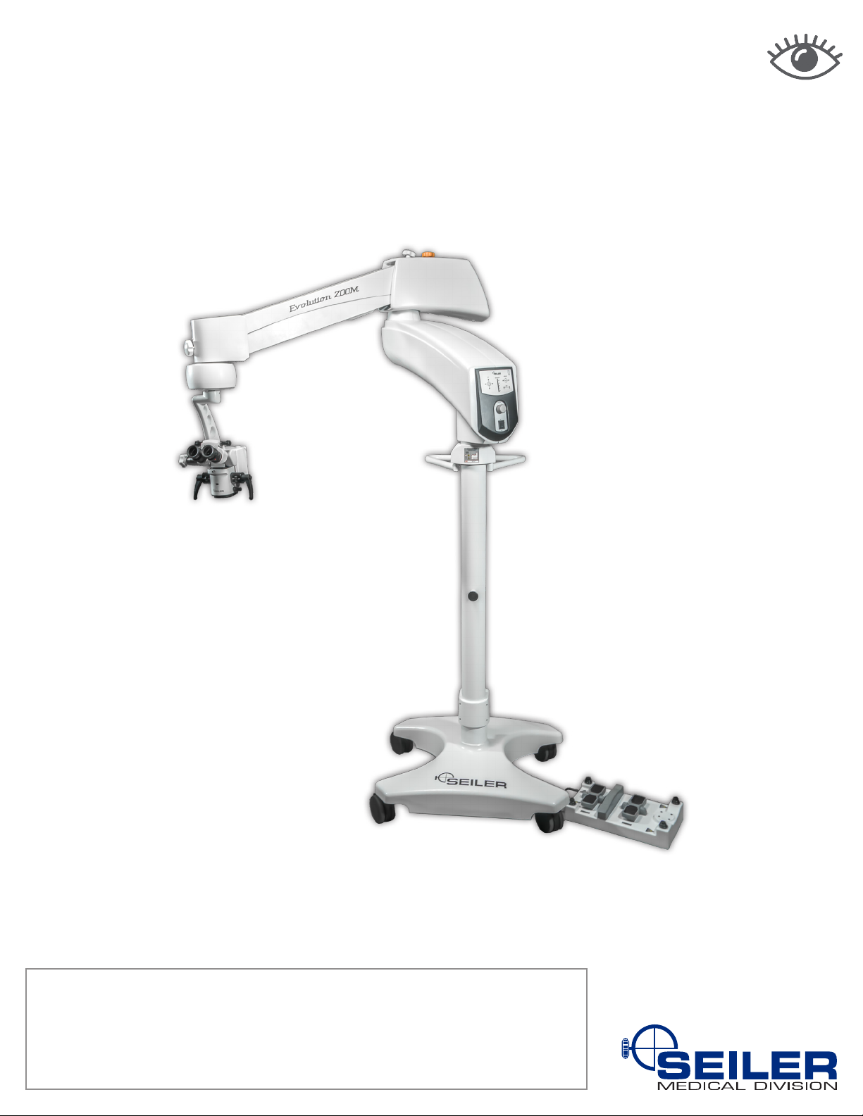
Evolution Zoom
Opthalmology Operating Microscope
User’s Manual

2
INTRODUCTION.................................................................................................................................................4
INTENDED USE..................................................................................................................................................5
PARTS AND COMPONENTS .............................................................................................................................5
INSTALLING THE EQUIPMENT.........................................................................................................................9
Unpacking .......................................................................................................................................................9
Installing the Base.........................................................................................................................................10
Installation Location ......................................................................................................................................11
Using Transformers.......................................................................................................................................11
Electric Connections .....................................................................................................................................11
USING THE MICROSCOPE .............................................................................................................................13
Moving the Unit .............................................................................................................................................13
Switching On The Unit ..................................................................................................................................15
Adjusting Diopter...........................................................................................................................................16
Adjusting Interpupillary Distance...................................................................................................................16
Adjusting Magnication .................................................................................................................................16
Adjusting Focus.............................................................................................................................................16
Adjusting Light Level.....................................................................................................................................17
Using The Xy System (Optional)...................................................................................................................17
Using The Inclinable Binocular Head............................................................................................................17
Ultraviolet (UV) Filter.....................................................................................................................................17
MAINTENANCE AND HYGIENE ......................................................................................................................18
Switching Bulbs During Use (Only For Units With Halogen Bulb) ................................................................18
Replacing A Burnt Out Bulb (Only For Units With Halogen Bulb) .................................................................18
Led Reliability And Lifetime (Only For Units With Led Source).....................................................................19
Replacing A Blown Fuse ...............................................................................................................................19
Repairing The Equipment .............................................................................................................................19
CLEANING........................................................................................................................................................20
ACCESSORIES ................................................................................................................................................21
Image Splitter................................................................................................................................................21
Video Camera ...............................................................................................................................................21
Video Camera Adapter..................................................................................................................................21
Digital Photographic Camera Adapter...........................................................................................................21
Second Observer Accessory.........................................................................................................................21
Image Inverter...............................................................................................................................................21
Multifunction Pedal........................................................................................................................................22
Fixed Binocular Head (45º) ...........................................................................................................................22
Zoom System................................................................................................................................................22
Filters ............................................................................................................................................................22
MECHANICAL DATA........................................................................................................................................22
Mechanical Data ..........................................................................................................................................22
Electrical Data...............................................................................................................................................23
Optical Data ..................................................................................................................................................23
TRANSPORTATION, STORAGE AND ENVIRONMENTAL CONDITIONS ....................................................24
DISCARD ..........................................................................................................................................................24
TROUBLESHOOTING......................................................................................................................................25
SYMBOLS.........................................................................................................................................................26
Table of Contents

3
WARNING .........................................................................................................................................................27
TERM OF WARRANTY.....................................................................................................................................27
CONTACT INFORMATION ...............................................................................................................................27
OWNERS RECORD..........................................................................................................................................28
NOTES ..............................................................................................................................................................28
WARRANTIES ............................................................................................................................................ 29-30
CERTIFICATES OF COMPLIANCE ........................................................................................................... 31-32
DECLARATION OF CONFORMITY ........................................................................................................... 33-34

4
Manufacturing Geospatial Medical Planetarium
The divisions of Seiler Instrument
Design Solutions
High tech. High touch.
Introduction
To Our Valued Professionals,
On behalf of the Seiler Medical Division, I would like to thank you for your recent purchase. We stand by our
products and are thrilled that when choosing one of the most important aspects of your practice, you chose us.
We are proud to say that, as a company, we have over 70 years’ experience in the optical eld. We have the
expertise to provide you with modern, reliable devices that incorporate some of the most advanced optical design
tools on the market. This product’s intent is to amplify an image while providing the user with an exceptional level
of comfort, improved visual acuity, and provide awless maneuverability for any ofce or hospital.
All of our products are manufactured according to strict medical and ISO standards. We also ensure all optical
components have undergone an anti-reective, multi-layer treatment; guaranteeing the efciency of the system
and enhancing the longevity of all of our products. Along with strict manufacturing standards and rigorous
testing, we also stand behind all of our products by offering a lifetime warranty on all optics and mechanics for
microscopes purchased in the United States, as well as a 3-year warranty on all international purchases.
Every Seiler Medical Division team member is here to provide you with outstanding service, quality, and
knowledge. Our number one priority is, and always will be, providing 100% customer satisfaction to every one of
our customers. If you need any further information about the equipment or just have a question, please contact us
using the information below.
Thank you again for your purchase and we look forward to serving all of your optical needs for years to come.
Sincerely,
Dane Carlson
Medical Division Manager
Seiler Medical Division
Toll Free: (800) 489-2282
Local: (314) 968-2282
Email: [email protected]
Web: www.seilerinst.com

5
Intended for use
An operating or surgical microscope is an optical instrument that provides the surgeon with a stereoscopic, high
quality magnied and illuminated image of the small structures in the surgical area.
Parts and Components
The Seiler Evolution Zoom Microscope is divided into modules (Figure 1).
Figure 1: Modules of the Seiler Evolution Zoom Microscope
Atlantico Systems Ltd.
34 Oldeld
Kingston, Galway
Ireland
www.atlanticosystems.com
Phone: +35391443609
Seiler Instrument & Mfg. Co, Inc.
3433 Tree Court Industrial Blvd.
St. Louis, Missouri 63122
USA
Toll Free: (800) 489-2282
Local: (314) 968-2282
Email: [email protected]
www.seilerinst.com

6
MODULE FUNCTIONS AND FEATURES
Column The column provides mechanical support to the equipment.
Control Box The control box contains the electronic circuits for the microfocusing, illumination
brightness control, zoom and XY system functions of the microscope.
Illumination Box Light is generated by the illumination box.
For microscopes with halogen bulb source, the light is supplied to the working area by
means of an optical ber cable to the microscope’s optical module.
The equipment is also available with LED source.
Pantographic
Arm
The pantographic arm is the structural module between the illumination box and the
optical module.
Optical Module The optical module comprises the objective lens, continuous magnication system
(zoom), and the binocular head.
A joystick is used for adjusting zoom, light level and focus multifunctional pedal.
Multifunctional
Pedal
The multifunctional pedal controls microfocus, on-off illumination, illumination
brightness, XY system and zoom (if applicable).
PLEASE NOTE: To make comprehensible the operating characteristics of each conguration of Seiler Evolution
Zoom Microscope, the following symbol is used:
(*1) – for microscopes with the continuous magnication system (zoom).
(*2) – for microscopes with the XY positioning system.

7
ATTENTION: Avoid overly tightening the knobs.
Figure 2: Main elements of the Seiler Evolution Zoom Microscope
Figure 3: Optical module with binocular head

8
Figure 4: Multifunctional pedal
Figure 5: Control panel
Figure 6: Joystick for adjusting zoom, light level and focus

9
PLEASE NOTE: Take care when handling the Fiber optic cable (only applicable to the conguration with
halogen bulb source). It is made up of extremely ne, very sensitive bers. Improper use, repeated stretching
and bending movements can cause damages that affect the performance or even rendering it useless.
PLEASE NOTE: The optical module is assembled in a sealed block. Maintenance activities shall only be
performed by the AUTHORIZED TECHNICAL ASSISTANCE.
PLEASE NOTE: The control box, the illumination box and the pantographic arm must be handled carefully,
because the external surfaces of these modules can be easily damaged. A sharp impact on these surfaces may
result in scratches or other damages.
The optical module is the most delicate part. Take care during use, transportation or handling. It is tted to a
specic support (Figure 3).
Installing the Equipment
PLEASE NOTE: Before any attempt to assemble or install the Seiler Evolution Zoom Microscope, please read
carefully and thoroughly the present User’s Guide.
The assembly and install activities shall only be performed by authorized technicians.
Seiler Instrument shall NOT be liable for any other type of procedure NOT set forth herein used to install or
assemble this product, nor shall be liable for any misuse of tools.
Unpacking
The Seiler Evolution Zoom Microscope is placed into plywood boxes and foams to protect the equipment during
transportation and storage.
Check the boxes for damage or signs of violation: please contact Seiler Instrument immediately in the event of
any irregularity. The Seiler Evolution Zoom Microscope should ideally be transported into its original packaging,
which shall be kept for further use.
Please check whether the box contains the items set out below:
• This User’s Guide
• Base
• Column
• Control box, illumination box and pantographic arm, already assembled
• Screw to fasten the base to the column
• Accessories, if applicable
• AC Multi-voltage cable 90-240V~
• Protective cover for the optical module
• 1 spare halogen bulb (only for Seiler Evolution Zoom Microscope with halogen bulb)
• 2 5A fuses
• Fixing pin for optical module support / XY system (*2), optical ber (for the microscope with halogen bulb
source) and electric cables already installed
• Optical module (discrete or zoom) already connected to its support system
• 1 pair of knobs of the optical module
• 1 pair of autoclave protectors knobs of the optical module
• Multifunctional pedal (*1) and/or (*2)

10
Assembling the base
When assembling the base:
1. Place two boxes around 5” thick under the base to support it when it is sitting on the neck.
2. Remove the two countersunk screws with a 7/32” hex wrench.
3. Place the two spacers between the plate and the stabilizer bar with the white pads facing you and bolt it on with
the two bolts supplied with the spacers.
4. Add outer bolt to leg without the spacer. Start a few threads.
5. Add spacer to the inner bolt hole, insert bolt. Tighten both.
6: Make sure leg attachments protrude outward as shown in photo 6.
1
2
5
4
3
6

11
Installation Location
The equipment shall be installed and operated indoors.
The following are instructions regarding the device’s installation location:
CAUTION: Spilling or evaporating ammable materials (e.g. cleaning agents) may cause re or
electrical shock when in contact with electrical parts.
CAUTION: Do NOT cover the power supply ventilation openings.
ATTENTION: The selected location should have relative humidity of 55 ± 15 % and ambient
temperature of 22 ± 3 °C.
CAUTION: Do NOT install the device:
• Near areas where large amounts of water are used.
• Where it is exposed to direct sunlight.
• In places where ventilation devices and air conditioners blow directly on the device.
• In places where heating devices directly affect the equipment.
• In unsafe places.
• In dusty environments.
• In a saline or sulfurous environment.
• In areas with high temperature or high humidity.
• In a freezing or condensing environment.
Using Transformers
If it is necessary to use a transformer, it shall be insulated type.
Do NOT use auto-transformers, because they may damage the device and put the user at risk.
Electric Connections
Electrical Panel/Column Connection
The electrical panel cover is fastened to the column with screws (Figure 2).
The cables shall be connected as indicated (Figure 7).
Figure 7: Electrical panel connections: internal part
of the panel cover (left) and the column (right)

12
Figure 8: Frontal view of the electrical panel of the column
Figure 9: Lower View of pantographic arm (electrical connection)
Electrical Panel External Connection
Connect the cables as indicated below:
Connect the Power cable to the AC connector on the electrical panel of the column (Figure 8). The device can be
connected at any level of voltage ranging from 90-240V~, 50/60 Hz (adjusted automatically to properly work in
these ranges).
Make the connection between the multifunctional pedal cable and the electrical panel as indicated (Figure 8).
Pantographic Arm Connection
Connect the microfocus / zoom cable to the connector indicated on the pantographic arm (Figure 9).
Insert the XY connection cable to the XY connector (*2) (Figure 9).
Connect the video system power cable to its connector, if applicable (Figure 9).

13
ATTENTION: Please take care when connecting cables as the connector pins are fragile.
CAUTION: The grounding terminal must be connected to an active grounding point.
Failing to do so may cause electrical shock, damage the device or cause it to NOT operate properly.
PLEASE NOTE: The device is immune to electromagnetic radiation within the limits specied under the EN
60601-1-2 standard and the updated version of IEC 60601-1-2.
Using the microscope
Using the microscope
ATTENTION: Before any attempt to operate Seiler Evolution Zoom Microscope, please read
carefully and thoroughly the present User’s Guide. This device may only be used by qualied
personnel.
Moving the Unit
The Seiler Evolution Zoom Microscope has been designed to be easily adjusted and handled whilst also
ensuring maximum comfort and stability.
Before using the Seiler Evolution Zoom Microscope, one can move it from one place to another and change
the position of the main modules to meet specic demands, since the followings instructions are considered
(Figure 10 and Figure 11):
To move the microscope with the base to the desired place, release the brakes of the 4 swivel casters. Move
the microscope by the column. After the base is placed on the required place, press the brakes for locking the
wheels.
The level of the base can be set using the Knob to raise or down the swivel casters, so as to place them on a
horizontal plane (Figure 10).
To adjusting the optical system to a specic position, make sure the swivel casters are properly locked (Figure
10). Then, loosen the knobs indicated and place the optics in the required position (Figure 11). After that, re-
tighten the Knobs (do NOT over-tighten them).
It is preferred to place the optical module as near as possible do the column, for improving stabilization.
To rotate the optical module vertically, release knob E. This may be slightly difcult, since the system is
assembled with a preload to prevent the optical module from falling/rotating involuntarily (Figure 2 and Figure 11).
The knob E is set in factory for a specic range of load. When many accessories are assembled, it may be
necessary to increase its preload, adjusting the disc spring washers of the brake mechanism of the knob E
(chapter 8) for greater stiffness. This shall be accomplished according to the following steps (Figure 12):
• Remove the cover indicated.
• Disassemble the screw and the knob E.
• Take apart the disc spring washers 1 and 2.
• Disassemble the body part.
• Apply additional torque to the adjusting nuts in such a way that they increase the preload on the disc spring
washers 3 to 8. Then, low strength thread-locking compound shall be applied to the adjusting nuts to prevent
them from loosing.
• Reassemble all the mechanism, apply low strength thread-locking compound to the screw assembled into the
knob E.

14
ATTENTION: Never use the optical module or the microfocus motor covers as a rest or support to pull, push,
raise or move the equipment. Only use the column or its handle to move the unit.
Figure 10: Swivel casters with brakes
Figure 11: Knob positions of the microscope

15
Figure 12: Brake mechanism of the Optical Module (knob E)
ATTENTION: A spring inside the pantographic arm ensures its smooth and precise movement. The spring’s
tension is NOT pre-set in the factory, because it must be released for transportation. When assembling the
microscope, this spring must be set by its adjustment knob (Figure 11). Where accessories are added to the
optical module, the weight to be balanced by the pantographic arm is increased, so the knob must be turned
anti-clockwise. Become aware of eventual downward movement of the optical system, especially when adding
accessories.
IDEAL SETTING: When moved upwards or downwards, the pantographic arm remains in the new position
without having to tighten the xing Knob of the pantographic arm.
Switching on the Unit
• Connect the AC Power Cable to the Electrical panel and to the grounding electrical socket (Electrical Panel
External Connection).
• Press the Main On/Off Switch at the Control panel (Figure 5).
• Adjust the illumination brightness by turning the button at the Control panel (Figure 5). To control the
illumination level by the multifunctional pedal, press one of the two Illumination On/Off buttons, followed by the
reduction or increase button (Figure 4).
PLEASE NOTE: The illumination source only operates when the multifunctional pedal cable is connected
to its connector (Figure 8).
CAUTION: The multifunctional pedal’s electric circuitry is NOT waterproof. Avoid spilling water directly onto
it. Before cleaning the oor on which the unit is placed, make sure to hang up the pedal in its transport handle at
the column (section 7.6 and Figure 2).

16
Adjusting diopter
The diopter adjustment aims at adapting the microscope to the user’s eyes, so as to obtain a proper image view
for particular person and work condition. This adjustment allows for both eyes to see focused-way object.
The diopter adjustment can be performed by rotating a ring located below the eyepiece. There is a visible trace to
be used as reference mark during this adjustment. Before carry out any adjustment, verify that zero (0) mark on
the ring coincides with the xed reference trace. It is possible to adjust between –6 and +6 diopters (Figure 13).
Adjusting interpupillary distance
The interpupillary distance adjustment aims at the adaptation of the equipment to the personnel in order
to achieve the best work adjustment. The ideal condition is reached when the user views a single image
(overlapping of eyepieces images).
Models equipped with xed binocular head (optional) can have the interpupillary adjustment made manually at the
boxes that support the eyepieces (Figure 3).
When the microscope comprises inclinable binocular head, interpupillary adjustment can be performed by
releasing a knob (Figure 3).
Adjusting magnification
The Seiler Evolution Zoom Microscope has continuous magnication (zoom).
The continuous zoom magnication system (5x to 30x) is controlled by the multifunction pedal or the joystick
(Figure 4 and Figure 6).
To select the magnication, simply activate the Adjustment Pedal or the Joystick, for increasing or reducing the
zoom. The selected magnication is shown on display.
Adjusting focus
• Center the microfocus system by pressing the centralization button in the upper right side of the control panel
(Figure 5).
• Loosen the knob of the pantographic arm joint (Figure 11), then put the optical module in a distance from the
working that are approximately the focal length of the objective lens in use. Re-tighten the knob to x the
pantographic arm.
• The ne focus adjustment can be performed by pressing the multifunctional pedal or the joystick (Figure 4 and
Figure 6).
• Two red indicator lights on the control panel correspond to downward or upward movement of the microfocus,
so as to indicate the direction of adjustment. When the microfocus reaches its end-limit, a beep is emitted if the
pedal is still pushed down (the indicator light remains lit up in this condition) (Figure 4 and Figure 5).
• For an extra-ne focus adjustment, one may selected the maximum possible magnication of the optical
module, then nd the best possible focus using the microfocus system. This will mean that, for increases to
other controls, the focus will already be at its optimum (section 6.5).
• If required, adjust the diopter or the interpupillary distance (sections 6.3 and 6.4).
Figure 13: Diopter adjustment

17
Figure 14: Drum with lters (left) and the sequence of lters seen by the main observer (right)
Adjusting light level
• Commands for adjusting the light level can be via multifunctional pedal, control panel or joystick (Figure 4,
Figure 5 and Figure 6).
Using the XY system (optional)
This section only applies to microscopes equipped with XY system.
• The XY system can be moved using the foot stick (Figure 4)
• As focus adjustment (section 6.6), light indicators show the movement of XY system and a beep is emitted
when the end-limit is reached (Figure 5).
• To center X and Y axes at the same time, press the center button located at the control panel (Figure 5).
Using the inclinable binocular head
The Inclinable Binocular Head can be inclined manually. In order to do this, incline the ocular lens manually to the
position desired (Figure 3).
Ultraviolet (UV) filter
The Seiler Evolution Zoom Microscope is supplied with conventional lters.
In addition, an anti-ultraviolet (UV) lter is also supplied. They come ready-tted from the factory, screwed into
drum of the lters. Their purpose of it is to prevent the passage of ultraviolet light (the image appears slightly
yellow through the binocular).
To select a specic lter, rotate the drum knob (Figure 14).

18
Maintenance and Hygiene
ATTENTION: Before any attempt to perform maintenance activities with the Seiler Evolution Zoom
Microscope, please read carefully and thoroughly the present User’s Guide. These tasks shall only be
executed by qualied personnel.
Switching bulbs during use (only for units with halogen bulb)
• In order to avoid undesirable interruptions in work when a bulb burns out, the Seiler Evolution Zoom
Microscope is provided with a redundant bulb, which is assembled and ready for use.
• Switching between bulbs is performed by turning a selection switch on the illumination box (Figure 2).
• It is recommended to replace the burnt out bulb as soon as possible.
Replacing a burnt out bulb (only for units with halogen bulb)
• Shift the main switch on the control panel to OFF (Figure 5) and disconnect the power plug from socket (Figure
8).
• Check whether the equipment is hot. If so, wait a few minutes (approximately 15 minutes) until it is cooled.
• Loosen 4 screws holding the illumination box cover, and remove it (Figure 15).
• Release 2 electrical sockets in which the halogen bulb is inserted (Figure 15).
• Release 2 screws from the bulb housing (Figure 15).
• Remove the bulb housing by pulling it out (slide tting) (Figure 15).
• Replace the burnt out bulb and reassemble the illumination box (Figure 15).
Figure 15: Halogen bulb in the illumination box
ATTENTION: Never touch the bulb.
PLEASE NOTE: When reassembling the device, do NOT invert the position of the power sockets. If this
happens, light will be emitted from bulb, but the position of the optical ber inside the illumination box will NOT
match the light bulb in operation. As a result, light will NOT go through the optical ber and, thus, the surgical
eld will NOT be lighted. The correct operation of the equipment must be veried by test immediately after light
bulbs are replaced.

19
Figure 16: Changing the fuses
LED reliability and lifetime (only for units with LED source)
• The LED source selected is one of the most reliable light sources in the world today. It has passed a rigorous
suite of environmental and mechanical stress tests, including mechanical shock, vibration, temperature
cycling and humidity, and has been fully qualied for use in extreme high power and high current applications
(paragraph 9.2).
• Failure rate: very low.
• Lifetime: lumen maintenance of greater than 70% after 60,000 hours.
• In case of LED technical issues, please contact the AUTHORIZED TECHNICAL ASSISTANCE.
Replacing a blown fuse
• Shift the main switch on the control panel to OFF (Figure 5) and disconnect the power plug from socket
(Figure 8).
• The fuse holder located on the electrical panel of the column covers 2 safety devices inside (Figure 8) Open
the cover and replace the blown fuse. Only 5A fuses shall be used (2 spare components are supplied).
Repairing the equipment
• To ensure an extended lifetime of the Seiler Evolution Zoom Microscope , the user is encouraged to
periodically consult Seiler Instrument to check the condition of the equipment and perform maintenance
as necessary. The AUTHORIZED TECHNICAL ASSISTANCE are reserved the right to repair or to perform
periodical maintenance or part replacement, whenever necessary.
• In the event of any defect in The Seiler Evolution Zoom Microscope , consult Seiler Instrument immediately
after receiving the product.
CAUTION: The equipment and its parts must be discarded according to the applicable environmental and
discarding regulations. Always check if the device component presents risks to the personnel and the environment,
in order to ensure safety discard, in accordance with the applicable laws (Chapter 11).
PLEASE NOTE: Do NOT ship the Seiler Evolution Zoom Microscope to the supplier, without consulting the
AUTHORIZED SEILER DISTRIBUTOR.

20
Cleaning
General
• The general cleaning of The Seiler Evolution Zoom Microscope shall be carried out with lint-free clothes or
wipe tissues moistened in an appropriate non-abrasive cleaning agent. Steel-wire brushes, knives, erasers,
emery cloth, sandpaper, and other devices that produce an abrasive action or cause contamination shall NOT
be used.
• Water with neutral detergent is the most appropriate for the cleaning process. Do NOT use organic solvents
to clean the external surfaces of the equipment (such as gasoline, ethanol, kerosene), since they can harm
painted surfaces.
• Eyecups are threaded onto the eyepieces and it can be taken apart for cleaning purposes. Sterilization of them
shall NOT be carried out in autoclaves or ovens (Figure 17).
• The knob silicone covers of the optical module can be sterilized in autoclaves or ovens.
• Control components such as buttons may be shielded from contact by a plastic lm.
Caution: The equipment must be switched off and disconnected from the power outlet prior to the cleaning
process. Before reconnecting the unit to the power outlet, allow the cleaning material to dry completely.
Caution: The multifunctional pedal’s electric circuitry is NOT waterproof. Avoid spilling water directly onto it.
Before cleaning the oor on the unit is placed, make sure to hang up the pedal in its transport handle at the column
(Figure 2).
Caution: Do NOT tilt the unit during the cleaning procedure. This increase the risk of cleaning agents seeping
into the device and causing damage and electrical safety hazards.
Caution: The microscope shall NOT be exposed to dust and other contaminating substances. Always protect the
optical module with its protective cover when the unit is NOT being used.
Figure 17: Eyepiece eyecup of the optical module
Other manuals for Evolution Zoom
1
Table of contents
Other Seiler Microscope manuals


