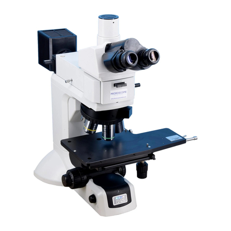
Seiler Microlux IV User manual

Microlux IV
LED
Operations Manual

3433 Tree Court Industrial Blvd.
St. Louis, MO 63122
(800) 489-2282
(314) 968-2282
Email: [email protected]
www.seilerinst.com

Contents
1. Parts Name 1
2. Specication 2
3. Installation 3
4. Operation 4
5. Installation & Operation for Attachments 5
6. Maintenance 5
7. Troubleshooting 10
8.Outts11

A3. Eyepiece
B2. Diopter
adjuster
A9. Notch for
attachment
A7. Clamp
B3. Aperture
diaphragm cover
B4. Condenser
Adjusting screw
(left & right)
A8. Condenser
A10. Filter
B5. Field diaphragm
revolver
B6. Condenser
thumb screw
B7. B8. Stage moving knobs
B9. Potentiometer
A11. Conden
set holder
A6. Mechanical
stage
A5. Objective
A1. Body
A4. Nosepiece
B1. Head thumb screw
A3. Eyepiece
1. Parts Name
Fig. 1-1
1

A12. Handle
B10. Condenser
focusing screw
A13. Power Input
A14. Fuse
B11. Power Switch
B12. Tension
adjustment ring
B13. Coarse
focusing knobs
B14. Fine
focusing knobs
Fig. 1-2
A1. Body A2. Seidentopf binocular head A3. Eyepiece A4. Nosepiece A5. Objective A6. Mechanical
Stage A7. Clamp A8. Condenser A9. Notch for attachment A10. Filter A11. Condenser holder
A12. Handle A13. Power Input A14. Fuse A15. Lamp Plate
B1. Head thumb screw B2. Diopter adjuster B3. Aperture diaphragm lever B4. Condenser adjusting screw
B5. Field diaphragm revolver B6. Condenser thumb screw B7. B8. Stage moving knobs B9. Potentiometer
B10. Condenser focusing screw B11. Power switch B12. Tension adjustment ring B13. Coarse focusing
knobs B14. Fine focusing knobs B15. Lamp plate thumb screw
2. Specication
2.1 Total magnications
10X
16X
4X
40X
64X
10X
100X
160X
20X
200X
320X
40X
400X
640X
100X
1000X
1600X
Objectives
Eyepiece
2

2.3 The other specication
2.3.1 Mechanical tube length: 160mm
2.3.2 Conjugate distance: Finite 195mm
Innite
2.3.3 Head: Seidentopf binocular (trinocular) 30º
Interpupillary adjustable distance is 50-75mm
Diopter adjustable range ±5,
Anti-fungal systems
2.3.4 Nosepiece: Quadplex or quinplex nosepiece
2.3.5 Mechanical Stage: Size 190mm X 140mm
X-Y travel 55mm X 78mm
2.3.6 Focusing systems: Coaxial coarse and ne focusing knobs
Coarse stroke 25mm, ne division 2 µ m
Condenser up-down range 25mm
2.3.7 Condenser: Abbe condenser, N.A. 1.25, Adjustable aperture
Aperture center is ajustable
2.3.8 Illumination: Koehler illumination system
2.3.9 Filter: Blue lter is for standard outts, green and amber is optional
2.3.10 Electric components: Input voltage AC 100-265V, 50/60Hz
Output voltage DC1.3.4V
3W LED lamp
Rotation potentiometer
Fuse 2A 5 X 20
2.2 Objectives (with eyepiece 10x)
3

Eyepiece
Binocular Head
1 X CCD Adaptor
Trinocular Head
Notch
obje
Condenser
N.A. 1.25
Filter
Fig. 2
3. Installation
Please install the microscope as follows:
Installation Process: (see Figure 3 on page 5)
1) Installing Lamp: LED is factory installed.
2) Installing binocular head
Loosen B1 binocular head thumb screw, put out A2 head, put it on top of body as in Fig. 1,
tighten the screw.
4

A15 Lamp plate
B15 Lamp plate
screw
Fig. 3
3) Installing objectives
Take out the objective from the packing box, and drive them into the holes of nosepiece orderly and
tightly according to times.
4) Installing eyepiece
Take out the eyepiece tube cover, then get the eyepiece from the packing bag, and insert into the tubes.
5) Installing condenser
a. Turn B13 coarse focusing knob, rise A6 mechanical stage to top;
b. Turn B10 condenser focusing screw, and take A11 condenser holder to the lowest position;
c. Loosen B6 condenser thumb screw, put the condenser to the holder, tighten B6 condenser thumb
screw.
d. Turn B10 condenser focusing screw, and raise the condenser to working position.
6) Installing blue lter or the other attachment
If blue lter will be used, the installation should be done before process 5, or do the installing during
process 5-C, then put A10 blue lter or the other attachment to the bottom hole of A8 condenser.
7) Installing the module attachment
The microscope can be with A9 module attachment and is multifunctional. Analyzer and wavelength
plate can be installed in A9 notch. Polarizer is installed over eld diaphragm or below the condenser.
Filter can be installed in the notch if the other attachment is in the bottom hole of condenser.
8) Installing CCD adaptor
Loosen the thumb screw in trinocular tube, put the CCD adaptor into trinocular tube, then tighten the
screw.
5

4. Operation
4.1 Operation process instructions
1) Turn power switch, adjust light
2) Place the sample
3) Put 10X objective into light
path and focus the sample
4) Adjust interpupillary distance
and diopter
5) Adjust condenser aperture
diaphragm
6) Adjust and center eld diaphragm
Put the objective into light path
and focus
Observe
Turn on B11 power switch and turn B9 pentiometer
Put the sample on A6 stage (open the clamp, and
put the sample on it), turn B7, B8 stage knobs to
put the sample into light path
Turn A4 nosepiece, put 10x objective into light path,
turn B13, B14 coarse and ne focus knobs.
Adjust A2 head to make two elds into one;
adjust B2 diopter adjuster to make diopter
for both eyes the same.
Adjust A8 condenser (B10 condenser focusing screw)
and aperture (B3 Aperture diaphragm lever).
Adjust eld diaphragm (B5 eld diaphragm
revolver), adjust center screw B4 to center
eld diaphragm.
4.2 Operation
1) Illumination
1. Conrm the voltage is available
2. Turn on power switch B11
3. Turn B9 potentiometer to adjust light
6

2) Sample placing
Put the sample (cover is up) on stage A6 and t it with clamp A7. Turn B7, B8 stage knobs to put the sample
into the light path (Fig. 4).
uTwo samples can be placed on the stage together
3) Focusing (Fig. 5)
Put 10x objective into light path, turn coarse
focusing knob B13, observe from right eyepeice
with right eye, then turn slowly ne focusing
knob B14 to make the image clear after nding image.
u The tension adjustment ring B12 can adjust the tension of the coarse and ne focusing unit to prevent
the stage from sliding down automatically and to improve the comfort of operation. Rotate clockwise to
decrease tension, rotate counter-clockwise to increase tension.
u Don’t turn left and right coarse and ne focusing knobs in different directions with power at the same
time, if so, the focusing system will be damaged. (Fig. 6)
4) Interpupillary distance and diopter adjustment
a. Interpupillary distance adjustment
Interpupillary distance is different for everyone, so interpupillary
distance should be adjusted before using binocular microscope.
Please take the two eyepiece tubes to turn until the bright rings
observed by two eyes are in superposition entirely. (Fig. 7)
b. Diopter adjustment (Fig. 8)
As focusing for binocular, user should observe right eyepiece with right eye and make the right eyepiece
clear by focusing adjustment, then observe the left eyepiece at the same time, adjust the diopter ring of the
left eyepiece tube to make the image of the left eyepiece clear as same as the right eyepiece.
Fig. 4
Fig. 5
Fig. 6
7

5) Condenser and aperture diaphragm adjustment
a. Condenser up-down
Turn the condenser focusing screw B10 to adjust the
distance between condenser front and the specimen,
and change the equal illumination to obtain the best
brightness.
b. Aperture diaphragm adjustment
Stir the handle of iris aperture of condenser to adjust
size of iris aperture for ajusting the contrast of the
specimen.
6) Centering eld diaphragm (this process is for microscope with eld
diaphragm)
a. Put 10x objective into light path, turn B5
condenser focusing screw, adjust condenser up or down to get the
image of eld diaphragm.
b. Observe throught eyepiece, turn B10 condenser focusing screw, adjust
condenser up or down to get image of eld diaphragm.
c. Turn B4 condenser adjusting screw to move the image
to the center of eld.
d. Put 40x objective into light path, turn B5 eld diaphragm revolver to
make the eld diaphragm image bigger than eld diaphragm.
Please center it again if the image is not in center.
4.3 Usage of immersion oil objective
The 100x objective of B series microscope can be used for observation even without immersion oil. However,
adding moderate immersion oil between the front lens of 100x objective and the cover glass of specimen can
make the image clearer. Please pay attention that air bubbles and impurities cannot be in the immersion oil,
otherwise, the image would be affected.
First, take 40x objective which has been focused well out from bright path, then take 100x objective into bright
path. At this time, nosepiece or stage moving knob should be turned slightly, and also slightly turn ne focusing
knob to clear away the air bubble of immersion oil, otherwise, the air bubble would affect the image badly.
Fig. 7
Fig. 8
8

u After immersion oil is used, the oil of specimen and the microscope surface should cleaned by absorbent
cotton, lens paper, gauze or soft cotton cloth with moderate mixture of pure industrial alcohol and ether
(proportion 1:4)
u Standard thickness 0.17mm cover glass should be chosen when high times objective used, and thickness
error should be within 0.01mm, otherwise, image denition would be affected.
4.4 Points of attention after using
4.4.1 Power of microscope should be turned off after using and the plug should be pulled out. If immersion
oil used, clean objective and specimen. Finally, cover the microscope with dust cover.
4.4.2 Please take eyepiece and objectives out of microscope if not being used for a long period of time.
Place eyepiece and objectives into drier with drying agent. Cover microscope with dust cover.
5. Installing and using camera and CCD attachment
5.1 Installing
Connect the C-mount with CCD camera or connect with camera adapter, then connect it with c-mount, nally
put it into microscope.
5.2 Using
First get a clear image from eyepiece, then pull out lever on the side of trinocular head and collect image with
camera. Clear image should be in screen. Adjust B14 ne focusing knobs to get it clear if image isn’t clear.
6. Maintenance
6.1 Clean microscope
6.1.1 Do not touch the lens with hand. Dust on lens should be cleaned by soft brush, absorbent cotton or
lens paper with a mixture of alcohol and ether (proportion 1:4)
6.1.2 Alcohol and ether are ammable, please keep them away from re. Be careful when turning power on
and off.
6.1.3 Don’t clean painted metal and galvanizing metal with organic solvent such as alcohol, ether or the
mixture of both. Silicon cloth or soft cleaning preparation is suggested to clean it.
6.1.4 Plastic should be cleaned by soft cloth with clear water.
6.2 Environment of using and placing
6.2.1 Microscope should be used and placed in a cool, dry, non-dust, non-shake and non-corrosive
environment.
6.2.2 Microscope should be used in environment of indoor temperature 0º – 40º C and maximum relative
humidity of 85%.
6.2.3 Removing equipment is suggested to be installed when microscope is used in heavy humidity area to
avoid fungus and mist damage.
6.2.4 Please pay attention to prevent the microscope from violent shaking and vibration in applications and
carrying. Don’t drag it on the surface of worktable to avoid damage to microscope and worktable.
6.3 Replacement of LED
6.3.1 Turn off power and pull out plug.
6.3.2 Lay aside microscope reliably, unscrew the knurled thumb screw of the lamp housing cover on the
underside of base.
6.3.3 Pull over the lamp housing cover.
6.3.4 Order LED lamp, assembly and replace.
6.3.5 Close the lamp housing cover and screw the knurled thumb screw.
* after working for 10 hours or more, it’s best to turn off the microscope for 30 minutes.

6.4 Replacement of fuse (shown in Fig. 8)
6.4.1 Cut off power of microscope and pull out th plug.
6.4.2 Unscrew fuse cap in the back of the base. Remove old fuse.
6.4.3 Replace with a new fuse and screw on fuse cap.
7. Troubleshooting
In the period of using, if any trouble occurs, please refer to the following chart for some common resolutions.
Trouble
Power on but
no light
Brightness of view
eld isn’t enough
or uneven
Cause
Plug is unreliable
Bulb is broken
Fuse is broken
Brightness isn’t
adjusted correctly
Objective isn’t in
correct position
The size of iris
aperture is too small
Remedy
Plug in again
Change bulb
Change fuse
Adjust rotation
potentiometer
Put the objective
in correct position
Adjust the size of
iris aperture
10

Cause
Lens (objective, eyepiece,
condenser,light collector)
has dust
Position of condenser
is too low
Cover glass of specimen
doesn’t meet the
requirement
Cover glass of specimen
isn’t in up direction
Surface of objective lens
is dirty (especially it is
easy for the front lens of
40x objective to dip in
immersion oil)
Immersion oil isn’t used
for 100x objective (oil)
Immersion oil doesn’t
meet the requirment
There is a bubble in
immersion oil
Size of iris aperture isn’t
proper
Position of condenser is
too low
Objective isn’t in correct
position
Specimen isn’t placed
correctly
Cover glass of specimen
isn’t in the up direction
Cover glass doesn’t meet the
requirement
Interpupillary distance
isn’t adjusted correctly
Diopter isn’t adjusted
correctly
Trouble
Brightness of view eld isn’t
enough or
is uneven
Image isn’t clear
(contrast or denition
isn’t enough)
One side of image is
dark or image is
moving as focsuing
Objective touches
specimen as changing
low times objective to
high times objective
Image observed by two
eyes aren’t in
superposition entirely
It is easy for eyes to be
tired during observing
Remedy
Clean it
Higher condenser
Use required thickness cover
glass (0.17mm)
Place specimen correctly
Clean it
Use immersion oil
Use immersion oil supplied by
us
Clear the bubble way
Adjust the size of iris aperture
Readjust the position of
condenser
Make the objective in correct
position
Place specimen levelly on stage
and clip it with clamp
Place specimen correctly
Use required thickness cover
glass (0.17mm)
Adjust interpupillary distance
according to two eyes
Readjust diopter
11

We are here to serve you!
If you have any questions regarding Seiler’s products or services,
please feel free to contact us.
Toll-Free: 800.489.2282
Local: 314.968.2282
Fax: 314.968.3601
www.seilerinst.com
•Microscope Division Manager
Dane Carlson
•Corporate Sales Representative
Nicole Rasch
•Technical Product Information
Tony Leise
•Bulb Order Information
Sandra Jeremich
PRECISION MICROSCOPES
A Division of Seiler Instrument Company

Table of contents
Other Seiler Microscope manuals
Popular Microscope manuals by other brands
Richter Optica
Richter Optica MDS1 instructions
AmScope
AmScope ZM-4 Series user manual
VAST Technologies
VAST Technologies DMC-2513 user manual
3B SCIENTIFIC PHYSICS
3B SCIENTIFIC PHYSICS 1012403 instruction manual
Fluke
Fluke Fiber Inspection Series quick start guide
Optika
Optika B-510 Series instruction manual
