Seima Chios 191788 User manual
seima.com.au
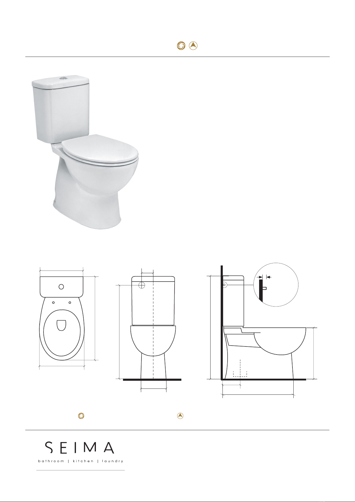
INSTALLATION GUIDE
CHIOS CLOSE COUPLED
CERAMIC TOILET SUITE
Clean Flush, Easy Care Height
− Clean Flush rimless pan design for an ecient, powerful flush
− Easy care height, pan height 425 mm
− White vitreous china
− Quick release, soft closing seat
− S trap only
− Bottom entry plumbing, optional back entry plumbing
− 140 recommended setout
− WELS 4 star 4.5/3L water saving flush
ORDER CODE 191788 Chios CF, bottom entry (old code: STO-402-00)
191789 Chios CF, back entry option (old code: STO-402-01)
CISTERN Bottom entry as standard, left and right inlet points.
Optional back entry plumbing.
PAN Close coupled with rimless pan design.
TRAPS Suitable for S trap installations.
SEAT Quick release, soft closing seat.
WELS 4 star rating 4.5/3 litre water saving flush. WELS licence 0296.
SETOUT 140 mm recommended.
FIXING This is a close coupled toilet suite — the cistern is fixed directly to the
pan and does not require wall fixing.
Pan may be bedded with cement base or using silicone sealant.
120
730
280
BACK ENTRY:
Setout position for
½” BSP nipple
350
370
670
425
810
520
140 rec
140 setout
recommended
BACK ENTRY:
½” BSP nipple
approx 22mm
projection from
finished wall
22
chios-cc-in | v 4.0
Easy care height – making it easier to get on and o the seat.
Rimless Clean Flush pan – for an ecient, powerful flush.
Please note
− Installation shall be in accordance with AS/NZS3500.
− All measurements are in millimetres. Height dimensions are to base of pan. Make allowance for bedding.
− Bedding: Fix pan to floor using a sand cement mixture of 3:1 to a depth of 60mm. Do not use lime or fast-drying cement.
− Bracket fixing: The pan should be bedded with an acetic cured silicone sealant and fixed with the brackets supplied.
− Dimensions are nominal and subject to normal ceramic manufacturing variations.
− Specifications may vary without notice as part of our continuous improvement practices.
− Clean with a damp cloth. Do not use abrasive cleaners, liquids or pastes. © Seima

CISTERN PACKAGE CONTENTS
1 x ceramic cistern lid
1 x ceramic cistern base
containing:
1 x flush valve
1 x bottom entry inlet valve
Cistern is supplied with
flush valve and Bottom
Entry inlet valve already
installed. See Diagram A.
2 x bolts w seals
For attaching
cistern to pan.
1 x plug
Only required if
installing back
entry (BE) version.
1 x rubber seal
For sealing outlet at
base of cistern.
1 x flush button
Half flush left,
full flush right.
Optional with BE versions:
1 x back entry inlet valve
Note: This component is only
supplied with Back Entry
version.
PAN PACKAGE CONTENTS
IMPORTANT
1Inspect the components before installation to ensure there are no visible defects. If a defect is found, do not install the toilet suite and contact the
supplier immediately. Claims for defects will not be accepted after the product has been installed.
2This wall faced toilet suite is suitable for a variety of set-ups:
CISTERN — accommodates Bottom Entry Inlet connection (left or right stop valve) or Back Entry Inlet connection.
PAN — accommodates S-trap installation.
3The toilet suite must be installed by a licensed plumber. Failure to do so may void the warranty.
Cistern comes
with flush valve
and Bottom Entry
inlet valve already
installed.
SEAT PACKAGE CONTENTS
1 x seat and lid
Soft closing. Has receptor holes that
slide onto pins on the pan.
1 x ceramic pan 2 x caps (white)
2 x floor screws (+ white plugs)
2 x pan plugs (white)
Optional fixing #2 — used to secure pan to floor. Plastic plug is placed into hole at
base of pan exterior; screw is rebated into plug. Cap is used to cover plastic plug.
2 x white caps (used to cover stainless plate with pin)
2 x plates with pin (seat locates onto pins)
2 x bolts (used for securing plate and pin to pan)
Page 2 of 4 | seima.com.au
INSTALLATION GUIDE
CHIOS CLEAN FLUSH CC TOILET SUITE
OPTIONAL EXTRA

DIAGRAM A
BOTTOM ENTRY SET-UP, AS SUPPLIED
overflow pipe
flush valve
cistern
bottom entry inlet valve
For back entry inlet, remove bottom entry inlet valve, plug hole,
install back entry inlet valve.
DIAGRAM B
INSTRUCTIONS TO CHANGE SET-UP
FROM BOTTOM ENTRY TO BACK ENTRY
STEP 3:
(see 4.4) Secure
cuff of back entry
inlet valve onto
overflow pipe and
fully tighten wing
nut.
STEP 1:
(see 4.1) Remove
bottom entry inlet
valve.
STEP 2:
(see 4.2) Fill hole
securely with plug.
overflow pipe
flush valve
cuff
½“ BSP nipple
back entry
inlet valve
cistern
REMOVE THIS
f
l
e
x
i
b
l
e
B
E
h
o
s
e
(
n
o
t
s
u
p
p
l
i
e
d
)
(see 4.6) Attach flexible hose (not supplied) to ½” BSP nipple water inlet.
back entry
inlet
valve
cistern
flush valve
DIAGRAM C
COMPLETED BACK ENTRY SET-UP
Page 3 of 4 | seima.com.au
1 S-TRAP PROCEDURE — SECURING THE PAN
CONNECTOR IN PLACE
Determine the centre of the pan and mark the centre line on the floor
and wall.
Work out the setout required. The recommended setout is 140mm.
(Note: Additional setout can be achieved using a 20mm pan
connector, not supplied.)
Position the pan connector into the floor outlet pipe (S-trap).
2 POSITIONING THE PAN
Use the centre line marked on the wall and floor to position the pan
(see Step 1.1). Push the pan into the installed plastic pan connector. It
is recommended that wedges are used to support the foot of the pan
during positioning.
3 BOTTOM ENTRY INLET CONNECTION — SET-UP
SEE DIAGRAM A.
The bottom entry inlet valve is already installed on the right side of
the cistern. The position can be swapped to the left side if required.
Connect the flexible inlet hose to the stop valve and water control
inlet valve on the wall. Leave flexible inlet hose unsecured for now —
for the bottom entry inlet connection, the flexible inlet hose will be
connected to the cistern’s inlet valve (see item 6 on next page).
4 OPTIONAL BACK ENTRY INLET CONNECTION —
CISTERN SET-UP
(Note: The cistern comes supplied with the bottom entry inlet valve
already installed and this needs to be removed.)
To set up the back entry connection, first remove the bottom entry
inlet valve on the right side the cistern. DIAGRAM B STEP 1.
Use the plug supplied to securely fill the hole in the base of the
cistern. DIAGRAM B STEP 2.
For ease of access while connecting the back entry inlet valve,
temporarily remove the flush valve from the cistern. (You may need
to rotate the base of the flush valve in order to position the overflow
pipe towards the rear of the cistern. This will enable the cu to be
attached as required.)
Place the cu of the back entry inlet valve onto the overflow pipe of the
flush valve, and fully tighten the wing nut. DIAGRAM B STEP 3.
Re-fit the flush valve and back entry inlet valve to cistern.
Connect the flexible BE hose to the ½” BSP nipple. Run the flexible
BE hose behind the flush valve, ensuring that the hose does not
obstruct the operation of the flush valve. DIAGRAM C.
5 SECURING THE PAN ON THE FLOOR
Cement fixing (optional fixing #1)
If using cement bedding, level the pan while the cement mixture is
workable. Fix pan to floor using a sand cement mixture of 3:1 to a
depth of 60mm. Do not use lime or fast-drying cement.
Important: Allow at least 24 hours for the cement mixture to set
before using the toilet.
Screw fixing (optional fixing #2)
Bed the pan with acetic cured silicone sealant, ensuring that the pan
is level. Then place the pan plugs into the floor fixing holes in the pan
and install the floor screws into place. The white caps can be used to
cover the plugs on each side of the pan.
Important: Do not over-tighten the bolts or screws as this may cause
the ceramic to crack and break.

6 FIXING THE CISTERN TO THE PAN
First check the alignment of the cistern and pan attachment holes —
place the cistern onto the pan and ensure that the holes align. Now
remove the cistern.
Place the rubber seal onto the plastic pipe outlet at the base of the
cistern and ensure it is securely attached. Locate the cistern outlet
(with rubber seal) onto the pan, ensuring a good fit.
If using bottom entry inlet, connect the flexible inlet hose (see
Step3) to the cistern’s water control valve on the base of the cistern.
(Ignore this if using back entry connection.)
Now secure the cistern to the pan using the two bolts with seals in
the cistern/pan attachment holes. SEE DIAGRAM D.
Flush the lines and connect the water supply and check the operation
of the cistern.
7 FITTING THE CISTERN LID
Fit the flush button into the cistern lid, with the half flush on the left
and full flush on the right. Ensure that the rubber feet of the flush
button connect and line up correctly with the flush valve inside the
cistern. Fit the cistern lid and push the buttons to check operation.
8 OPERATION AND MAINTENANCE
Press the half flush on the left side to save water and the full flush
on the right as required. Clean the toilet with liquid detergent and a
damp cloth.
Do not place water additives inside the cistern as this may have
chemicals that damage the valves and impair the functionality of the
cistern.
9 SEAT INSTALLATION INSTRUCTIONS
Secure the toggle bolts into the seat connection holes, ensuring that
the pins line up with the receptor holes in the seat. Once correctly
placed, ensure that the bolts are properly tightened.
Slide the white caps onto the plates with pins.
To fit the seat, slide it onto the pins. You may need to make
adjustments to position the seat correctly.
To remove the seat, put seat in upright position to expose the seat
release button at the base of the seat. To release, press button and lift
the seat upwards to remove it.
DIAGRAM E
floor fixing holes
(both sides of pan)
cistern/pan attachment
holes
seat connection holes
cistern outlet pipe hole
To fit seat, slide seat
down onto pins.
To remove seat, press
button in centre of seat.
cistern/pan
attachment
hole
cistern cistern
pan
cistern
STEP 1:
Place bolt, washer and
rubber seal through
cistern/pan attachment
hole in base of cistern.
(Do this on both sides.)
STEP 2:
Thread washer and
small white plastic
screw-nut onto thread
of bolt and tighten.
This will seal the base
of cistern against
leakage. (Do this on
both sides.)
STEP 3:
Now place cistern on top
of pan and locate bolts
into attachment holes
in pan. Place washer
and large wing-nut onto
thread and tighten. (Do
this on both sides.)
DIAGRAM D
Page 4 of 4 | seima.com.au
This manual suits for next models
6
Other Seima Toilet manuals


