Seima LIARA User manual
Large end of pan connector can
be trimmed to suit setout.
Threaded
section can
be trimmed to
required size.
IMPORTANT
1 Inspect the components before installation to ensure there are no visible defects.
If a defect is found, do not install the toilet suite and contact the supplier
immediately. Claims for defects will not be accepted after the product has been
installed.
2 This toilet suite is suitable for a variety of set-ups:
Cistern — accommodates either Back Entry Inlet connection or Bottom Entry Inlet
connection (left or right stop valve).
Pan — universal trap — accommodates S-trap installation or P-trap installation
(using appropriate connector; not supplied).
3 The toilet suite must be installed by a licensed plumber. Failure to do so may void
the warranty.
4 Installation must be in accordance with AS/NZS3500.
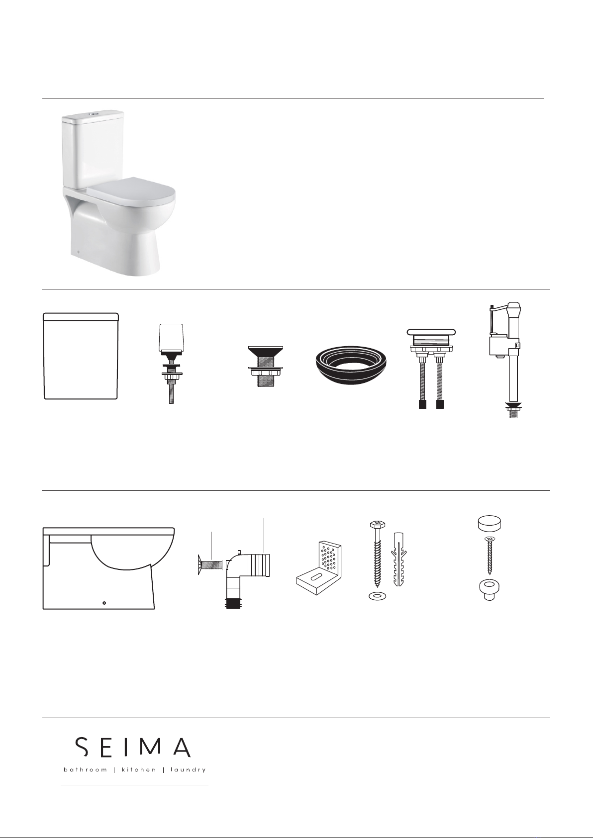
CISTERN PACKAGE CONTENTS
1 x ceramic cistern lid
1 x ceramic cistern base
Cistern is supplied with flush
valve and dual purpose inlet
valve already installed.
PAN PACKAGE CONTENTS
1 x ceramic pan 1 x pan connector
For connecting pan to floor
outlet pipe/S-trap.
1 x threaded section (with
flange plate)
Flange attaches to wall;
threaded section links to
pan connector.
2 x concealed fixing
brackets
Optional — can be
used to connect pan
to floor.
2 x floor bolts
(+ white plugs)
2 x washers
Optional fixing #2 — used
with fixing brackets to
secure pan to floor. Bolt is
inserted through bracket
base hole.
2 x caps (chrome plated)
2 x screws
2 x pan plugs (white)
Optional fixing #2 — used to
secure pan to concealed fixing
bracket. Plastic plug is placed
into hole in side of pan exterior,
screw is rebated into plug and
then screws into a hole in upright
section of bracket. Chrome cap
is used to cover plastic plug.
2 x bolts w seals
For attaching cistern to
pan. White component
at top enables hand
tightening.
2 x plugs
Plugs can be used to plug
holes in sides of pan if
required.
1 x rubber seal
For sealing outlet at
base of cistern.
1 x flush button
Half flush left, full flush
right.
Note: The cistern can
be adapted for bottom
entry plumbing. The
bottom entry inlet
valve shown above is
included.
bottom entry
inlet valve
liara-wf-in | v 200 | page 1 of 4
INSTALLATION GUIDE
LIARA WALL FACED
seima.com.au
Please note
− Installation shall be in accordance with AS/NZS3500.
− All measurements are in millimetres. Height dimensions are to base of pan. Make allowance for bedding.
− Bedding: Fix pan to floor using a sand cement mixture of 3:1 to a depth of 60mm. Do not use lime or fast-drying cement.
− Bracket fixing: The pan should be bedded with an acetic cured silicone sealant and fixed with the brackets supplied.
− Dimensions are nominal and subject to normal ceramic manufacturing variations.
− Specifications may vary without notice as part of our continuous improvement practices.
− Clean with a damp cloth. Do not use abrasive cleaners, liquids or pastes.

bottom entry inlet port
hole for flexible hose
(on both sides of pan)
bracket fixing holes
(both sides of pan)
bottom entry water
control holes
cistern/pan
attachment holes
seat connection holes
cistern outlet pipe hole
All measurements are in millimetres.
Height dimensions are to base of pan.
Make allowance for bedding.
This toilet suite can be set up as either Bottom Entry Inlet or Back Entry Inlet.
INSTALLATION GUIDE
LIARA WALL FACED TOILET SUITE
1 S-TRAP PROCEDURE — SECURING THE PAN
CONNECTOR IN PLACE
Determine the centre of the pan and mark the centre line on the
floor and wall.
Work out the setout required. The recommended setout is 150mm
(setout range is 90-190mm).
You may need to trim the large end of the plastic pan connector
to fit the required setout. To trim, first remove the plastic ring and
rubber seal, then cut pipe to size. Refit rubber seal and plastic ring
securely, ensuring a good fit.
Position the pan connector into the floor outlet pipe (S-trap).
The height measurement from the floor to the centre of the pan
connector is 185mm.
Slot the threaded section (with flange plate) onto the pan
connector, ensuring that the flange plate is touching the wall. You
may need to trim the threaded section so that it fits properly.
Mark and drill the flange plate holes and secure the plate to the wall
with fixing screws. The pan connector is now installed.
2 POSITIONING THE PAN
Use the centre line marked on the wall and floor to position the pan
(see Step 1.1). Push the pan into the installed plastic pan connector.
It is recommended that wedges are used to support the foot of the
pan during positioning.
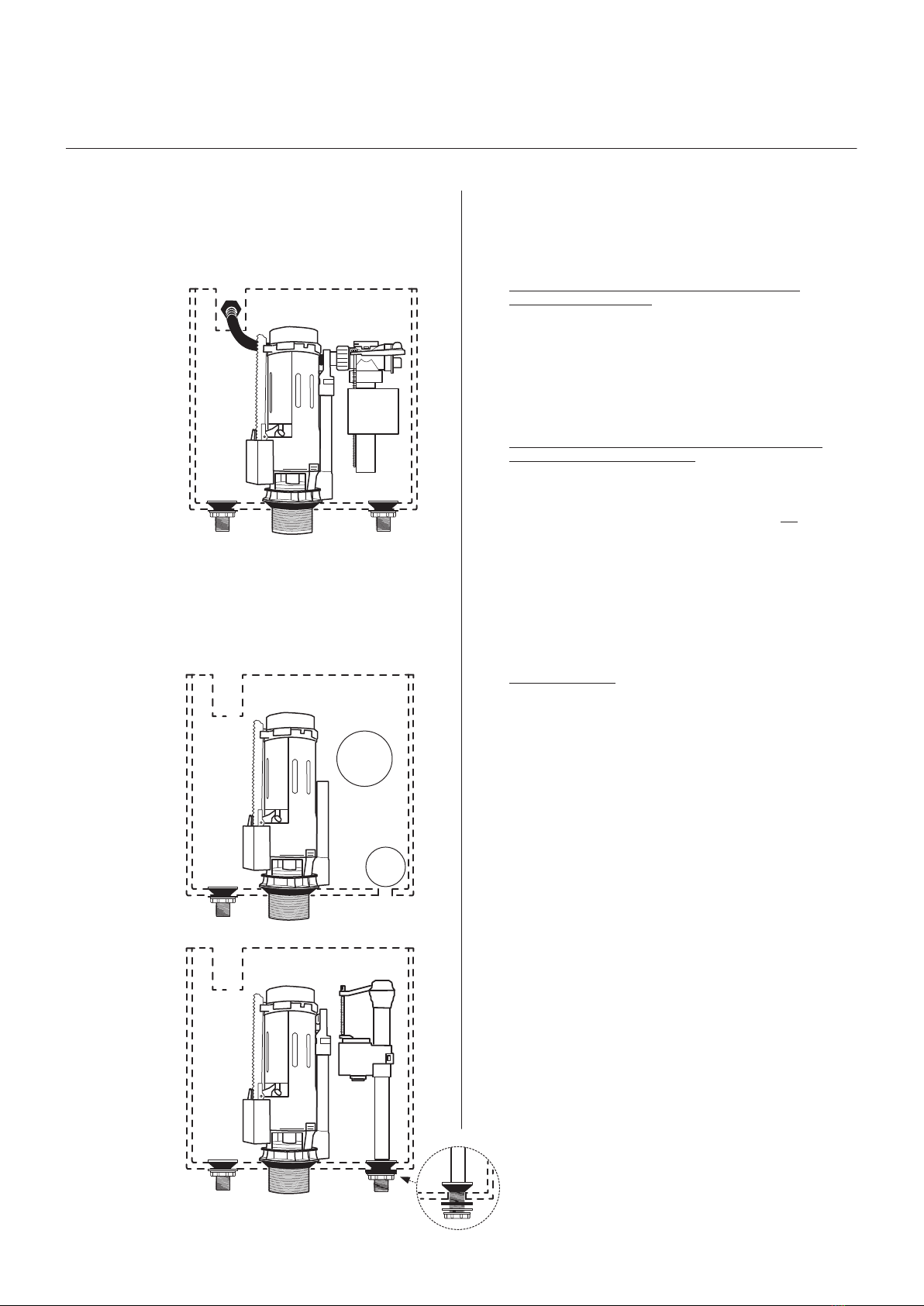
3 CISTERN — COMES SET UP FOR BACK ENTRY
INLET PLUMBING
Diagram A shows the cistern as supplied, with the inlet valve and flush
valve already installed. The flexible hose is ready for Back Entry inlet
plumbing (see Diagram B).
For Bottom Entry Inlet plumbing, refer to Step 5 and Diagrams C
andD.
Cistern setup as supplied.
The end of the flexible
hose is loose, ready to
be attached to the Back
Entry inlet nozzle (see
Diagram B).
NOTE: FLEXIBLE HOSE NOT
SUPPLIED.
DIAGRAM A
inlet
valve
cistern
flush valve
plug
(flexible hose not supplied)
Page 3 of 4 | seima.com.au
6 SECURING THE PAN ON THE FLOOR
Cement fixing (optional fixing #1)
If using cement bedding, level the pan while the cement mixture
is workable. Fix pan to floor using a sand cement mixture of 3:1
to a depth of 60mm. Do not use lime or fast-drying cement.
Important: Allow at least 24 hours for the cement mixture
to set before using the toilet.
Bracket fixing (optional fixing #2)
Bed the pan with acetic cured silicone sealant, ensuring that
the pan is level. Then position the concealed fixing brackets in
line with the bracket fixing holes. Screw the floor bolts in place
through the base of the brackets. Then secure the pan to the
brackets using the plastic pan plugs and rebated screws. The
chrome caps can be used to cover the plugs on each side of the
pan.
Important: Do not over-tighten the bolts or screws as this may
cause the ceramic to crack and break.
7 FIXING THE CISTERN TO THE PAN
(Note: The cistern fixes directly onto the pan and does not
require wall fixing.)
First check the alignment of the cistern and pan attachment
holes — place the cistern onto the pan and ensure that the holes
align. The back of the cistern and pan should line up so that the
assembled toilet suite will align with the wall. Now remove the
cistern.
Place the rubber seal onto the plastic pipe outlet at the base of
the cistern and ensure it is securely attached. Locate the cistern
outlet (with rubber seal) onto the pan, ensuring a good fit.
If using Bottom Entry inlet plumbing, refer to Step5 and install
the back entry inlet valve.
Now secure the cistern to the pan using the two bolts with seals
in the cistern/pan attachment holes.
Flush the lines and connect the water supply and check the
operation of the cistern.
8 FITTING THE CISTERN LID
Fit the flush button into the cistern lid, with the half flush on the
left and full flush on the right. Ensure that the rubber feet of the
flush button connect and line up correctly with the flush valve
inside the cistern.
Fit the cistern lid and push the buttons to check operation.
9 OPERATION AND MAINTENANCE
Press the left side half flush to save water and the full flush as
required.
Clean the toilet with liquid detergent and a damp cloth.
Do not place water additives inside the cistern as this may have
chemicals that damage the valves and impair the functionality
of the cistern.
4 BACK ENTRY INSTALLATION
Connect the flexible hose to the ½” BSP nipple in the wall outlet. Run
the flexible hose behind the flush valve, ensuring that the hose does not
obstruct the operation of the flush valve.
5 CISTERN SET-UP CAN BE ADAPTED FOR
BOTTOM ENTRY INLET PLUMBING
First remove two items: the back entry inlet valve and the plug in the
base of the cistern. Next, install the bottom entry inlet valve with plug in
the hole in the cistern base.
For Back Entry Inlet,
attach the loose end
of the flexible hose
to the ½” BSP nipple
water inlet in wall.
back entry
inlet
valve
cistern
flush valve
DIAGRAM B
The cistern setup after
the back entry inlet
valve and base plug
have been removed.
DIAGRAM C cistern
flush valve
Next, install the
bottom entry inlet
valve with plug
into the hole in the
cistern base. Place
the conical rubber
seal inside the cistern.
Outside the cistern
thread on the flat
rubber seal, white
plastic disc and white
plastic wing nut in
that sequence.
DIAGRAM D cistern
flush valve
bottom entry inlet valve
remove
plug
remove
back entry
inlet valve
(flexible hose not supplied)
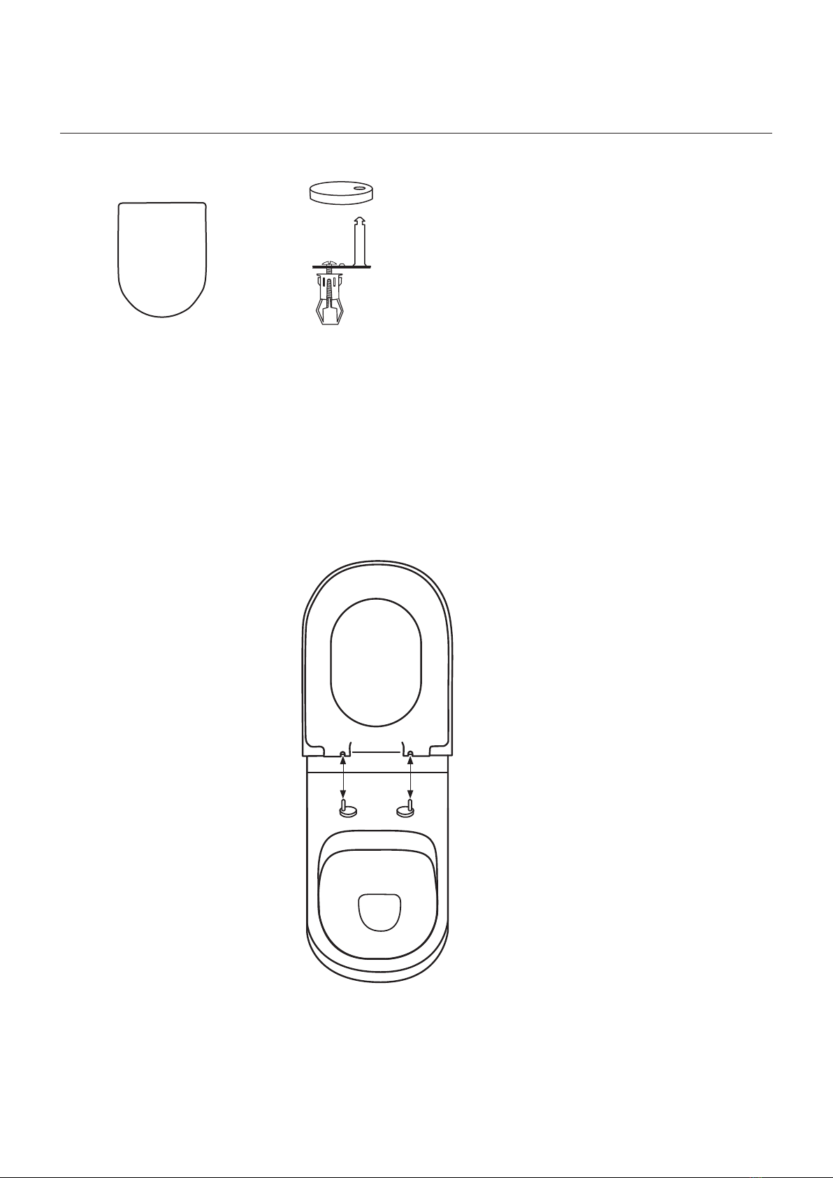
Secure the toggle bolts into the seat connection holes, ensuring that the stainless steel pins line up with the receptor holes in the seat.
Once correctly placed, ensure that the bolts are properly tightened.
Slide the stainless steel caps onto the plates with pins.
To fit the seat, slide it onto the stainless steel pins. You may need to make adjustments to position the seat correctly.
To release the seat, put the seat in an upright position, press the buttons on the seat and lift upwards.
To fit seat, slide seat down
onto stainless steel pins.
To remove seat, put seat in
upright position, press the
buttons on the seat and lift
upwards.
10 SEAT PACKAGE CONTENTS AND INSTALLATION
1 x seat and lid
Has receptor holes that slide
onto stainless steel pins.
2 x stainless steel caps (used to cover stainless steel plate w pin)
2 x stainless steel plates with pin (seat locates onto stainless steel pins)
2 x toggle bolts (used for securing stainless steel plate and pin to pan)
Page 4 of 4 | seima.com.au
This manual suits for next models
1
Other Seima Toilet manuals


Popular Toilet manuals by other brands


Kohler
Kohler REACH K-3991K-HC installation instructions

Setma
Setma waterGenie Compact Installation and operating instructions

Dyconn
Dyconn NIARA K81 Series product manual

Kohler
Kohler K-5401X installation guide

Uspa
Uspa UB-7035R Operating instructions manual

Danze
Danze Cobalt DC063330 installation instructions