Seima Modia STO-20 User manual
Modia / STO-20 Ceramic Wall Faced Toilet Suite
Installation Instructions .com.au
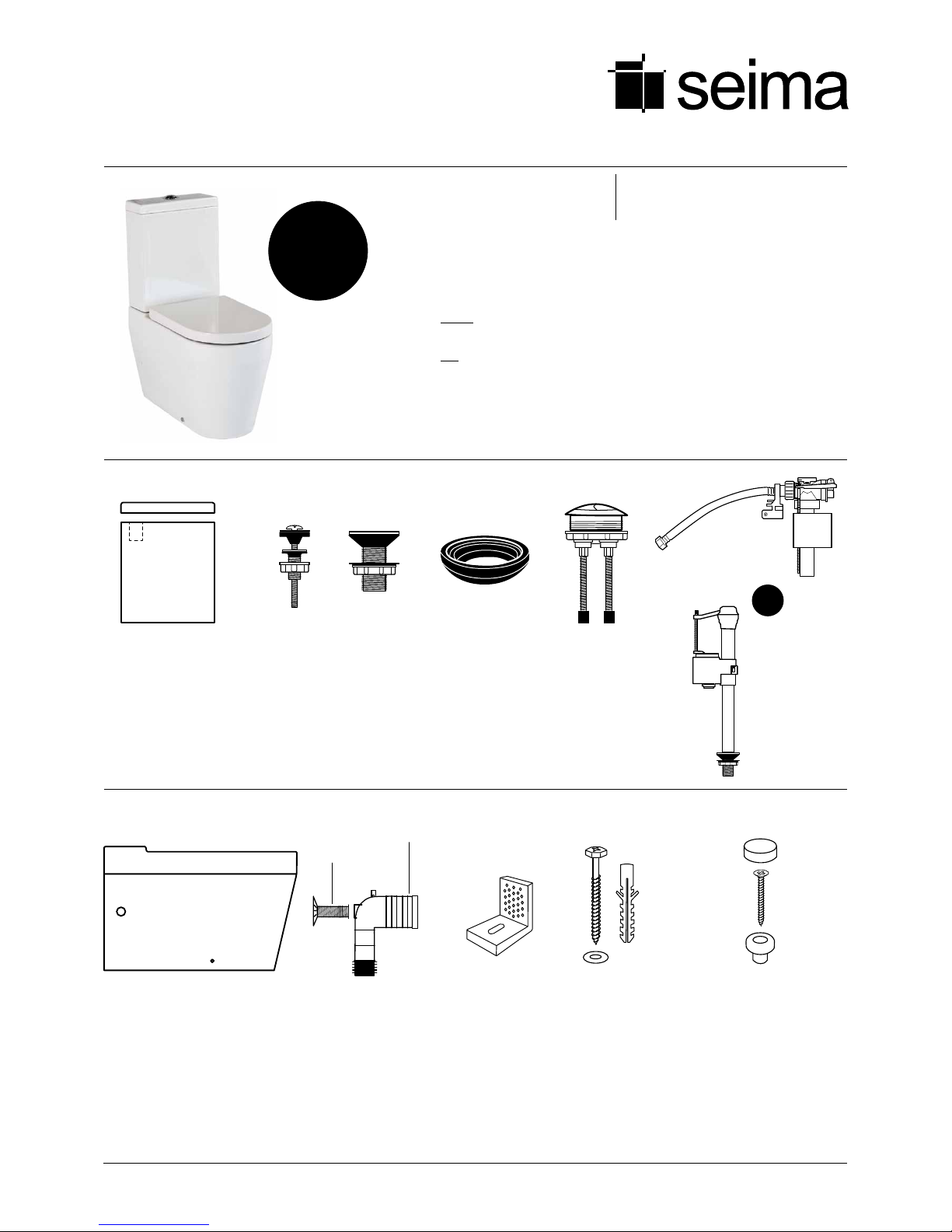
Cistern package contents
Important
1Inspect the components before installation to ensure there are no visible defects.
If a defect is found, do not install the toilet suite and contact the supplier immediately.
Claims for defects will not be accepted after the product has been installed.
2This toilet suite is suitable for a variety of set-ups:
nCistern — accommodates either Bottom Entry Inlet connection
(left or right stop valve) or Back Entry Inlet connection.
nPan — universal trap — accommodates S-trap installation or
P-trap installation (using appropriate connector; not supplied).
3The toilet suite must be installed by a licensed plumber. Failure to do so may void
the warranty.
4Installation must be in accordance with AS/NZS3500.
IN-Modia_STO-20 | v2.0X9000009 | page 1 of 4
Modia
STO -2 0
Order codes
STO-20-BE Back Entry inlet plumbing
STO-20 Bottom Entry inlet plumbing
OR
bottom entry
inlet valve
1 x back entry
inlet valve
Supplied with
STO-20BE.
1 x ceramic cistern lid
1 x ceramic cistern base
Cistern is supplied with flush
valve and bottom entry inlet
valve already installed.
2 x bolts
with seals
For attaching
cistern to pan.
3 x plugs
One required
if installing
back entry (BE)
version; others
can be used to
plug holes in
sides of pan if
required.
1 x rubber seal
For sealing outlet at
base of cistern.
1 x flush button
Half flush left, full
flush right.
Large end of pan connector
can be trimmed to suit setout.
Threaded
section can be
trimmed to
required size.
Pan package contents
1 x ceramic pan 1 x pan connector
For connecting pan to
floor outlet pipe/S-trap.
1 x threaded section
(with flange plate)
Flange attaches to wall;
threaded section links to
pan connector.
2 x concealed
fixing brackets
Optional — can be
used to connect pan
to floor.
2 x floor bolts
(+ white plugs)
2 x washers
Optional fixing #2 —
used with fixing brackets
to secure pan to floor.
Bolt is inserted through
bracket base hole.
2 x caps (chrome plated)
2 x screws
2 x pan plugs (white)
Optional fixing #2 — used
to secure pan to concealed
fixing bracket. Plastic plug
is placed into hole in side of
pan exterior, screw is rebated
into plug and then screws
into a hole in upright section
of bracket. Chrome cap is
used to cover plastic plug.
1 x bottom entry
inlet valve
Supplied with
STO-20.

S-trap procedure — Securing the pan
connector in place
1.1 Determine the centre of the pan and mark the centre line on the
floor and wall.
1.2 Work out the setout required. The recommended setout is
150mm (setout range is 90-190mm).
1.3 You may need to trim the large end of the plastic pan connector
to fit the required setout. To trim, first remove the plastic ring
and rubber seal, then cut pipe to size. Refit rubber seal and
plastic ring securely, ensuring a good fit.
1.4 Position the pan connector into the floor outlet pipe (S-trap).
The height measurement from the floor to the centre of the pan
connector is 185mm.
1.5 Slot the threaded section (with flange plate) onto the pan
connector, ensuring that the flange plate is touching the wall.
You may need to trim the threaded section so that it fits properly.
1.6 Mark and drill the flange plate holes and secure the plate to the
wall with fixing screws. The pan connector is now installed.
Positioning the pan
2.1 Use the centre line marked on the wall and floor to position the
pan (see Step 1.1). Push the pan into the installed plastic pan
connector.It is recommended that wedges are used to support
the foot of the pan during positioning.
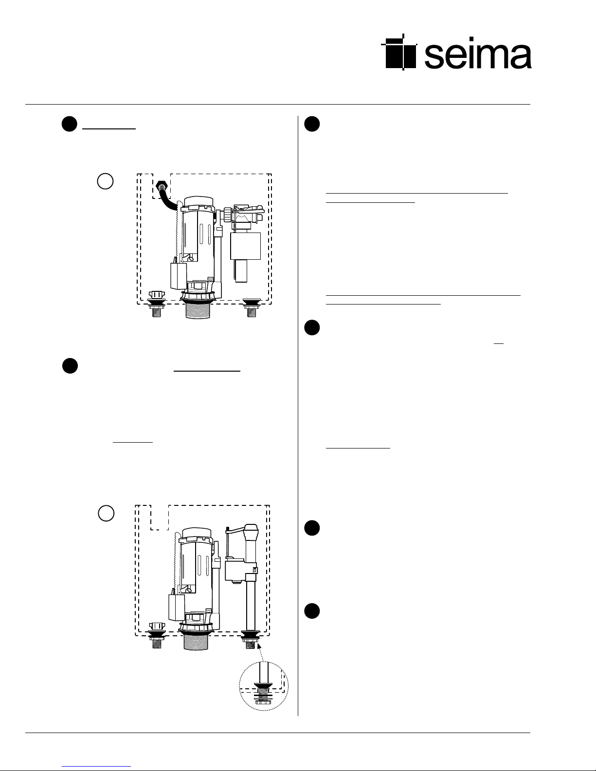
Cistern — set-up for Back Entry
inlet plumbing
Diagram A shows the cistern as supplied for Back Entry plumbing, with
the inlet valve and flush valve already installed. The flexible hose is
ready for Back Entry inlet plumbing (see Diagram B).
For Bottom Entry Inlet plumbing, refer to Step 5 and Diagrams C and D.
Modia / STO -2 0
Installation Instructions
1
2
3
X9000009 | page 2 of 4
bottom entry inlet port
hole for flexible hose
(on both sides of pan)
bracket fixing holes
(both sides of pan)
bottom entry water
control holes
cistern/pan
attachment holes
seat connection holes
cistern outlet pipe hole
All measurements are in millimetres. Height dimensions are to base of pan. Make allowance for bedding.
Cistern setup for Back Entry
plumbing. The end of the
flexible hose is loose, ready
to be attached to the Back
Entry inlet nozzle (see
Diagram B).
A
inlet
valve
cistern
flush valve
DIAGRAM
plug
plug
655
360
360
105
785
860
360
360
250
back entry inlet
setout position
for ½” BSP
nipple
22053
420
180
150 rec 150 setout
recommended
(range 90-190)
bottom entry inlet
port hole for
flexible hose
back entry inlet
½” BSP nipple
approx 22mm
projection from
finished wall
Securing the pan on the oor
6.1 Cement fixing (optional fixing #1)
If using cement bedding, level the pan while the cement
mixture is workable. Fix pan to floor using a sand cement
mixture of 3:1 to a depth of 60mm. Do not use lime or fast-
drying cement.
Important: Allow at least 24 hours for the cement mixture
to set before using the toilet.
6.2 Bracket fixing (optional fixing #2)
Bed the pan with acetic cured silicone sealant, ensuring that
the pan is level. Then position the concealed fixing brackets
in line with the bracket fixing holes. Screw the floor bolts in
place through the base of the brackets. Then secure the pan to
the brackets using the plastic pan plugs and rebated screws.
The chrome caps can be used to cover the plugs on each side
of the pan.
Important: Do not over-tighten the bolts or screws as this may
cause the ceramic to crack and break.
Fixing the cistern to the pan
(Note: The cistern fixes directly onto the pan and does not
require wall fixing.)
7.1 First check the alignment of the cistern and pan attachment
holes — place the cistern onto the pan and ensure that the
holes align. The back of the cistern and pan should line up so
that the assembled toilet suite will align with the wall. Now
remove the cistern.
7.2 Place the rubber seal onto the plastic pipe outlet at the base of
the cistern and ensure it is securely attached. Locate the cistern
outlet (with rubber seal) onto the pan, ensuring a good fit.
7.3 If using Bottom Entry inlet plumbing, refer to Step 5 and install
the back entry inlet valve.
7.4 Now secure the cistern to the pan using the two bolts with
seals in the cistern/pan attachment holes.
7.5 Flush the lines and connect the water supply and check the
operation of the cistern.
Fitting the cistern lid
8.1 Fit the flush button into the cistern lid, with the half flush on
the left and full flush on the right. Ensure that the rubber feet
of the flush button connect and line up correctly with the flush
valve inside the cistern.
8.2 Fit the cistern lid and push the buttons to check operation.
Operation and maintenance
9.1 Press the left side half flush to save water and the full flush as
required.
9.2 Clean the toilet with liquid detergent and a damp cloth.
9.3 Do not place water additives inside the cistern as this may have
chemicals that damage the valves and impair the functionality
of the cistern.
6
7
8
9
X9000009 | page 3 of 4
Back Entry installation
Connect the flexible hose to the ½” BSP nipple in the wall outlet.
Run the flexible hose behind the flush valve, ensuring that the hose
does not obstruct the operation of the flush valve.
4
.com.au
Cistern set-up for Bottom Entry
inlet plumbing
5.1 Connect the flexible inlet hose to the stop valve and water
control inlet valve on the wall. Then run the flexible inlet hose
through a port hole in the side of the pan. Pull the flexible inlet
hose upwards, to allow it to pass through the water control hole
on the pan upper. Leave flexible inlet hose unsecured for now
— for the bottom entry inlet connection, the flexible inlet hose
will be connected to the cistern’s inlet valve in Step 7.3.
5.2 The bottom entry inlet valve is already installed on the right
side of the cistern. The position can be swapped to the left side
if required.
5
B
For Back Entry Inlet,
attach the loose end
of the flexible hose
to the ½” BSP nipple
water inlet in wall.
back entry
inlet
valve
cistern
flush valve
DIAGRAM
plug
plug
The bottom entry
inlet valve installed
in the cistern base.
C
DIAGRAM cistern
flush valve
bottom entry inlet valve
plug
.com.au
Modia / STO -2 0
Installation Instructions
X9000009 | page 4 of 4
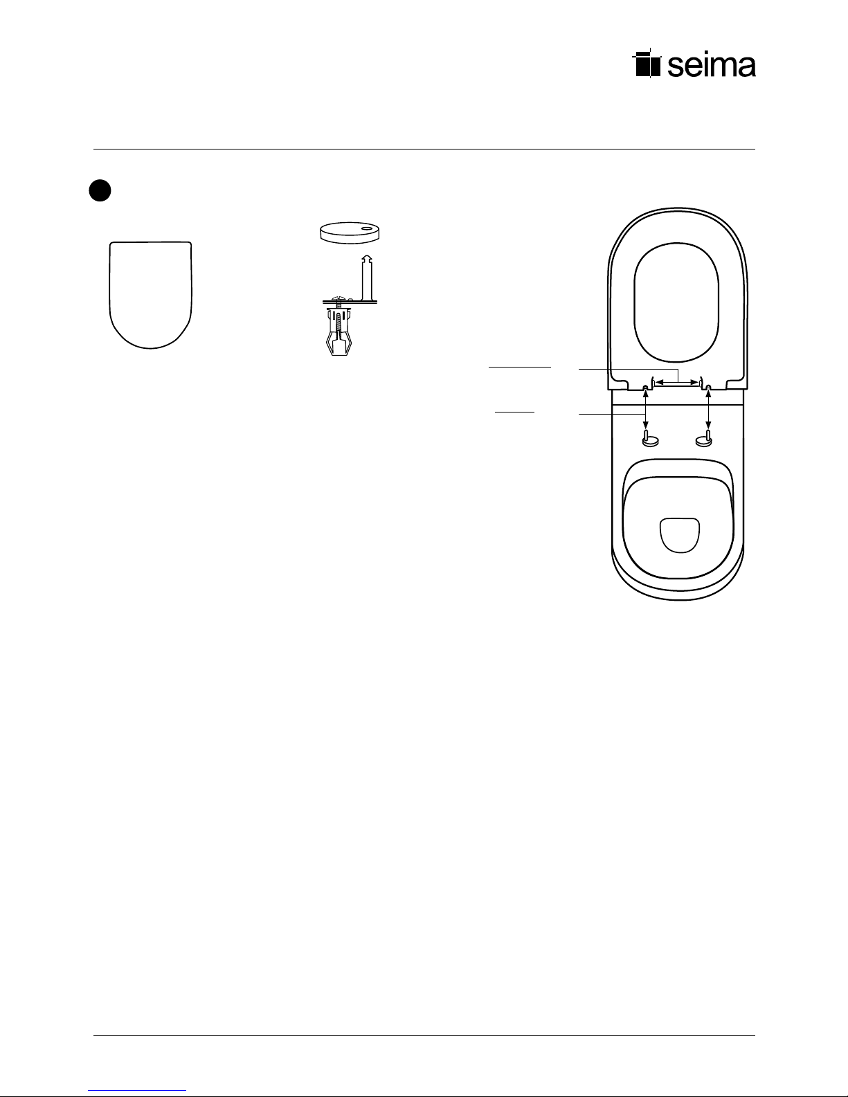
10.1 Secure the toggle bolts into the seat connection holes, ensuring that the
stainless steel pins line up with the receptor holes in the seat. Once correctly
placed, ensure that the bolts are properly tightened.
10.2 Slide the stainless steel caps onto the plates with pins.
10.3 To fit the seat, slide it onto the stainless steel pins. If you need to make
adjustments to position the seat correctly, go back to Step 9.1.
10.4 To remove the seat, put seat in upright position to expose the two chrome
seat release buttons at the base of the seat. To release, press both buttons
simultaneously and lift the seat upwards to remove it.
To fit seat, slide seat
down onto stainless
steel pins.
To remove seat, press
the two chrome buttons
at base of seat.
Seat package and installation
1 x solid construction seat
and lid — soft closing
Has receptor holes that slide onto
stainless steel pins.
2 x stainless steel caps
Used to cover stainless steel plate w pin.
2 x stainless steel plates with pin
Seat locates onto stainless steel pins.
2 x toggle bolts
Used for securing stainless steel plate
and pin to pan.
10
This manual suits for next models
1
Other Seima Toilet manuals


Popular Toilet manuals by other brands


Swiss Madison
Swiss Madison SM-WC424 installation instructions

Laufen
Laufen ILBAGNOALESSI One 8.2097.1 Installation

Separett
Separett Tiny installation manual

ECOWAY
ECOWAY KOMFY300 user manual

Cinderella
Cinderella TRAVEL installation manual

rba
rba RBA8847-100 Installation, operation and maintenance instructions

Woodbridge
Woodbridge B0970S installation manual

Kallista
Kallista P70080-00 installation guide

EcoLet
EcoLet 25e owner's manual

Laufen
Laufen ILBAGNOALESSI 82097.6 Installation instruction

Raritan
Raritan Crown Head CW912 Installation, operation and maintenance instructions

Ideal-Standard
Ideal-Standard Waverley Assembly and installation instructions