Schweitzer Engineering Laboratories, Inc. SEL-487B Data Sheet
5
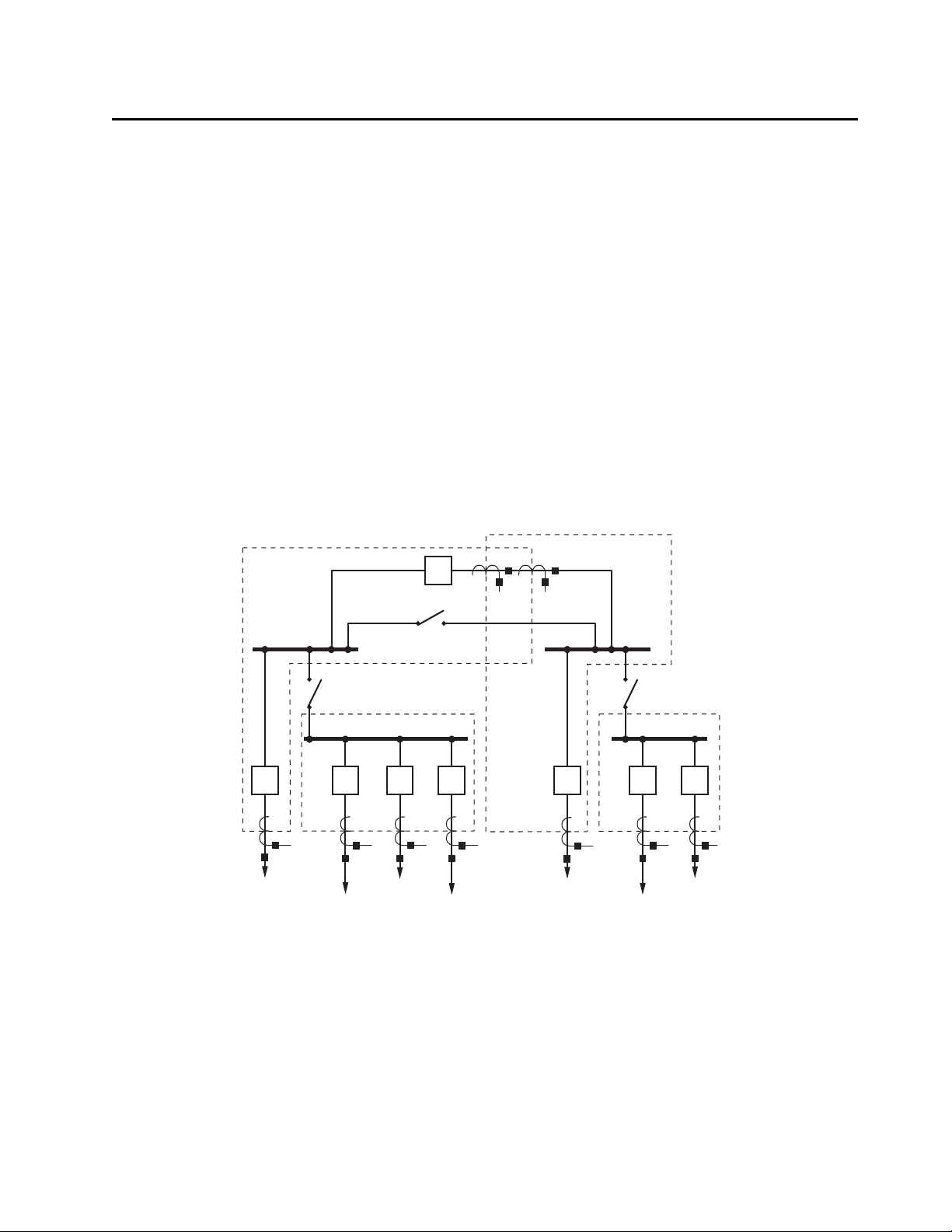
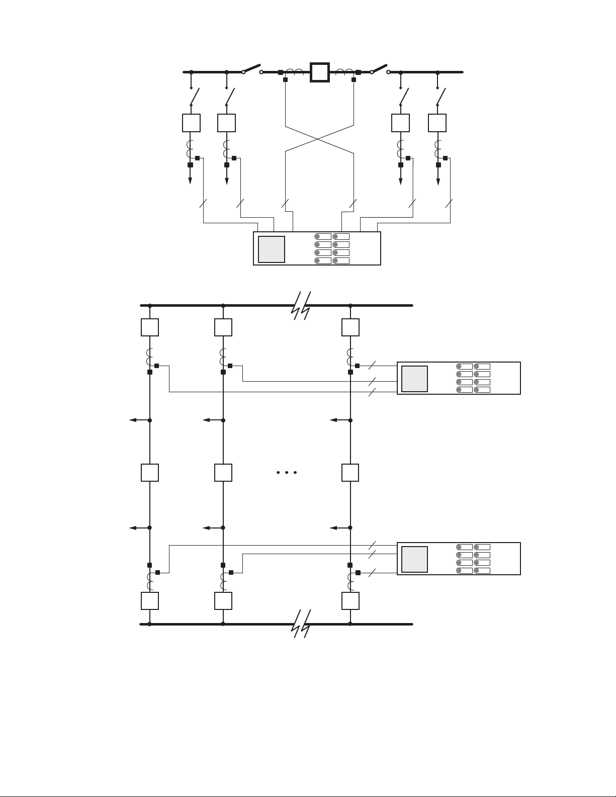
Closing disconnect DS2 combines Zone 1 and Zone 2,
resulting in a single zone. Figure 4 shows the new
protection zone configuration. In this combination, Zone
1 includes North and East bus-zones. Figure 5 shows the
new Zone 1 that includes bus-zones North and East.
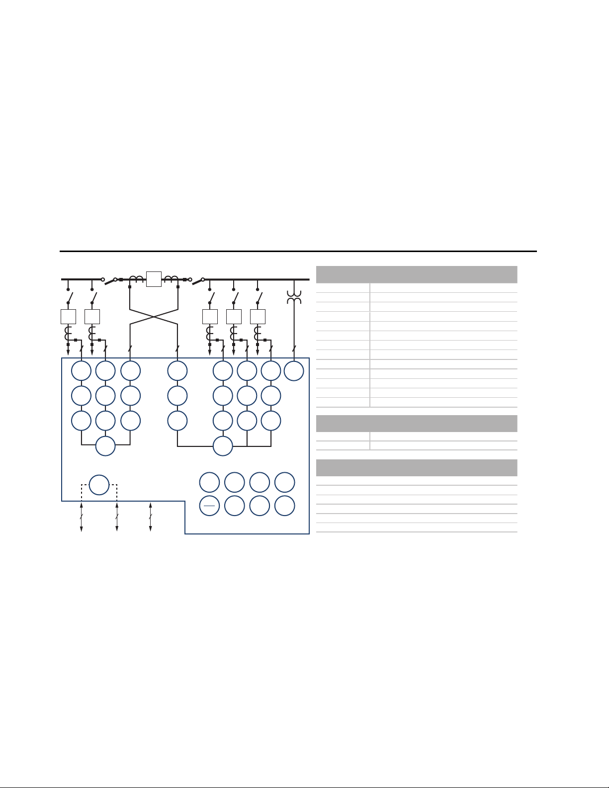
Zone Selection Logic
Busbar protection requires assignment of the correct cur-
rent values to the appropriate differential elements as a
function of user-defined conditions. To achieve this, the
SEL-487B employs a two-step process:
➤Evaluates the user-defined conditions.
➤Assigns the currents to the differential element of
the appropriate zone.
Current assignment conditions vary from simple to
complex. A simple condition would be a statement such
as “always include this terminal in the differential
calculations.” A more complex condition statement could
be “when Disconnect 2 is closed, and the transfer
disconnect is open.”
SELOGIC control equations provide the mechanism by
which the user enters the conditions for assigning the
currents to the differential elements when these
conditions are met. When a SELOGIC control equation
becomes true (e.g., the disconnect is closed), the relay
dynamically assigns the current to the differential
elements. Conversely, when the SELOGIC control
equation is false (the disconnect is open), the relay
dynamically removes the currents from the differential
elements. This is also true for the trip output. When the
SELOGIC control equation of a terminal is false, the relay
issues no trip signal to that terminal. Table 1 shows a
simple case where the disconnect status is the only
condition for the relay to consider.
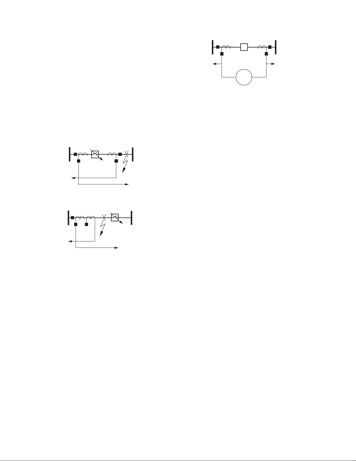
End-Zone Protection
To illustrate the flexibility of use of SELOGIC control
equations for user-defined conditions, consider the ease
of achieving end-zone protection with the SEL-487B.
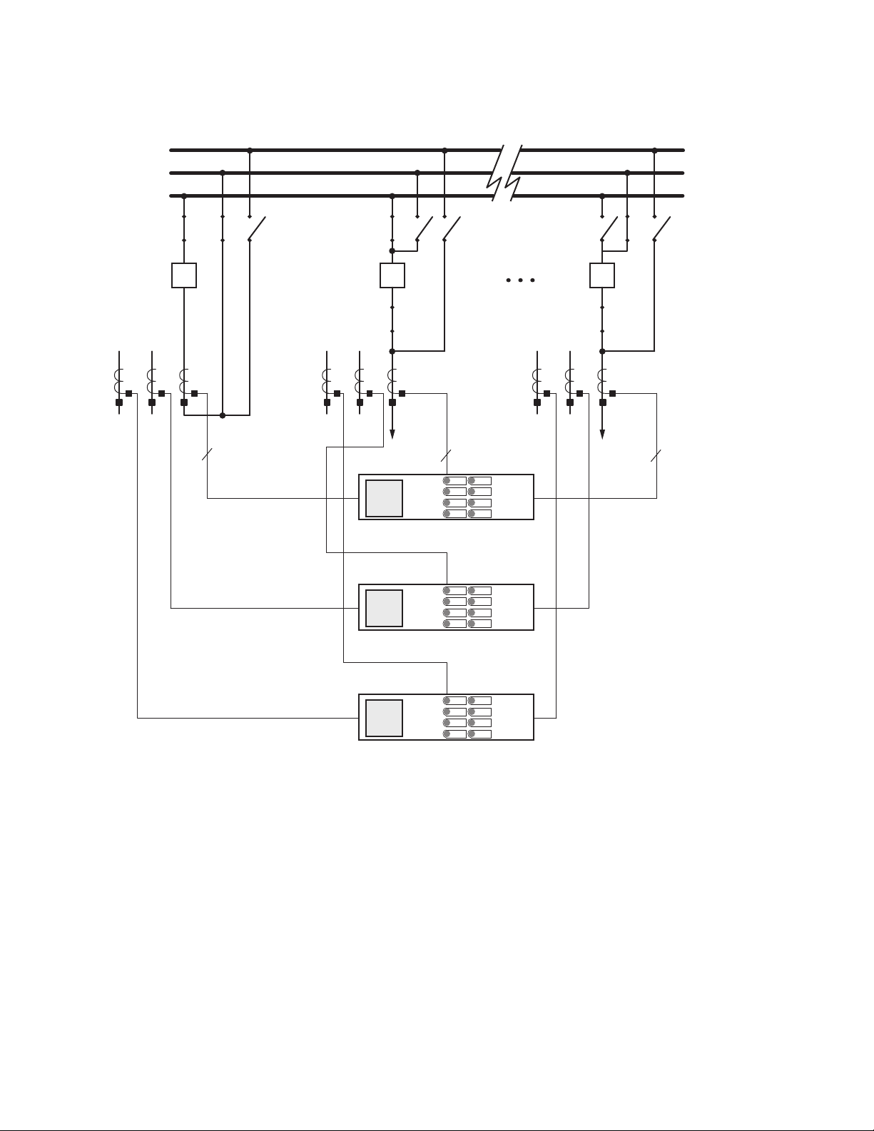
Figure 6 shows fault F1 between an open circuit breaker
and CT of a feeder at a substation. This area is a “dead”
zone because neither busbar protection nor local line
protection can clear this fault; the remote end of the
feeder must clear this fault. Because the feeder circuit
breaker is already open, operation of the busbar
protection serves no purpose. The busbar protection must
not operate for this fault.
Figure 6 Fault Between Breaker and CT
By including the circuit breaker auxiliary contact in one
of the SELOGIC control equations (Figure 7), we can
cause the value of the SELOGIC control equation to be
false when the circuit breaker is open, removing the
current from the differential element calculations. This
capability ensures stability of the busbar protection. By
our use of SELOGIC control equations and normal
communications channels to configure the protection
system, the relay sends a trip signal to the remote end of
the feeder.
Figure 7 Bus Protection Is Not Affected by Fault, F1;
Use Transfer Trip to Clear the Fault
Check Zones
The SEL-487B provides three completely independent
check zones, each with its own adaptive differential
element. Supervise zone differential elements by using
the independent check zones to monitor all incoming
sources and outgoing feeders on a per-phase basis.
During an internal fault, the check zone differential
element will assert. During an external fault, the check
zone element will remain deasserted.
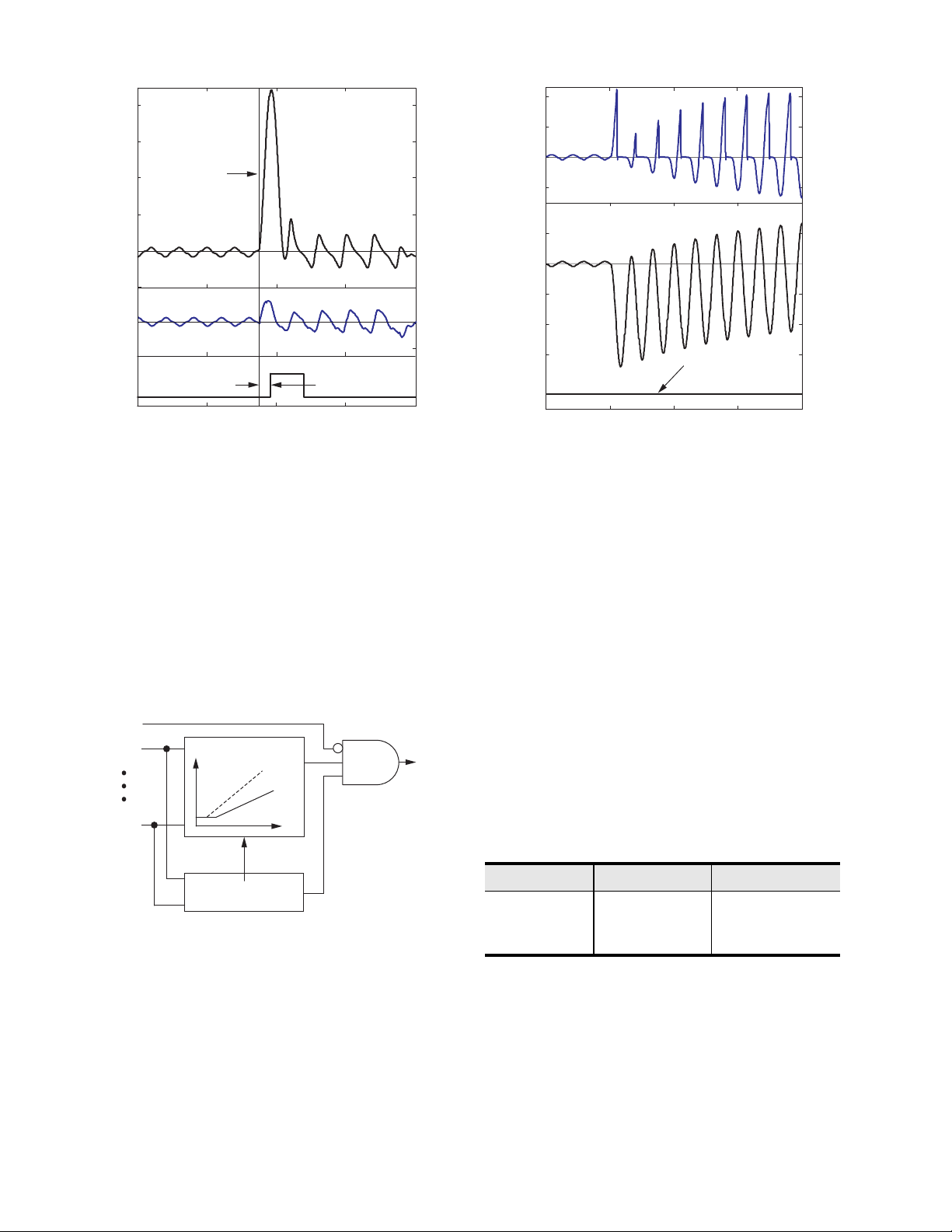
Differential Protection
The SEL-487B includes six independent current differ-
ential elements. Operating time for internal faults,
including high-speed output contact closure, is less than
one cycle. Figure 8 shows an example of an internal fault
and differential element operation.
Table 1 Conditions for Automatic Terminal Assignment
Example of
Condition
SELOGIC
Control
Equation
Result
Consider
Terminal in
Protection
Calculations?
Issue
Trip?
Disconnect is open False No No
Disconnect is closed True Yes Yes
Busbar Primary
Fault Current
Circuit
Breaker Open
End-Zone
Fault
52
F1
Busbar Primary
Fault Current
End-Zone
Fault
52a Auxiliary
Contact
52
F1