Sel SEL-487E-3 User manual

Schweitzer Engineering Laboratories, Inc. SEL-487E-3, -4 Data Sheet
Three-Phase Transformer Protection,
Automation, and Control System
Key Features and Benefits
The SEL-487E Transformer Protection Relay provides three-phase differential protection for transformer applications
with as many as six three-phase restraint current inputs. A second three-phase differential element is also supported for
busbar protection.
➤High-Speed Differential Protection. A two-stage slope adapts automatically to external fault conditions, providing
fast, sensitive, dependable, and secure differential protection, even for CT saturation and heavily distorted waveforms.
Two independent differential zones are available, one of which supports additional features that accommodate
transformer differential protection.
➤Inrush and Overexcitation Detection. Combined harmonic blocking and restraint features provide maximum
security during transformer magnetizing inrush conditions. Waveshape-based inrush detection addresses inrush
conditions that contain low second and fourth harmonic content.
➤Turn-to-Turn Winding Fault Protection. Innovative negative-sequence differential elements provide transformer
windings protection from as little as two percent turn-to-turn winding faults.
➤Restricted Earth Fault Protection. Three independent REF elements provide sensitive protection for faults close
to the winding neutral in grounded wye-connected transformers.
SEL-487E-3, -4 Transformer
Protection Relay

SEL-487E-3, -4 Data Sheet Schweitzer Engineering Laboratories, Inc.
2
➤Combined Overcurrent. Configurations exist for a wide variety of transformer applications. Use the combined
overcurrent elements for transformers connected to ring-bus or breaker and one-half systems. This feature
mathematically sums two terminal current inputs to form a single operating quantity.
➤Distance Protection. Mho or quadrilateral characteristics protect transformers and transmission lines with four
zones of phase distance and ground distance elements. Line harmonic blocking, load-encroachment, coupling
capacitor voltage transformer (CCVT) detection, and out-of-step blocking logic add security to your distance
protection scheme.
➤Transformer and Feeder Backup Protection. Adaptive time-overcurrent elements with selectable operating
quantity, programmable pickup, and time-delay settings provide transformer and feeder backup protection.
➤Reclosing Control. You can incorporate programmable three-pole trip and reclose of as many as six independent
breakers into an integrated substation control system.
➤Reverse Power Flow and Overload Condition Protection. The SEL-487E directional real- and reactive-power
elements guard against reverse power flow and overload conditions.
➤Synchronism Check. Synchronism check can prevent circuit breakers from closing if the corresponding phases
across the open circuit breaker are excessively out of phase, magnitude, or frequency. The synchronism-check
function has a user-selectable synchronizing voltage source and incorporates slip frequency, two levels of maximum
angle difference, and breaker close time into the closing decision.
➤Input/Output Scaling. The SEL-2600 RTD Module provides as many as 12 temperature inputs, and the
SEL-2505/SEL-2506 Remote I/O Modules provide a scalable number of discrete I/O points.
➤Two CT Input Levels. Selectable 1 A or 5 A nominal secondary input levels are available for any three-phase
winding input.
➤Large CT Mismatch Ratio. The relay can accommodate CT ratio mismatch as great as 35:1.
➤Breaker Failure. High-speed (less than one cycle) open-pole detection logic reduces coordination times for critical
breaker failure applications. Apply the relay to supply breaker failure protection for all supported breakers. Logic
for breaker failure retrip and initiation of transfer tripping is included.
➤IEC 60255-149 Compliant Thermal Model. The relay can provide a configurable thermal model for the protection
of a wide variety of devices. This function can activate a control action or issue an alarm or trip when equipment
overheats as a result of adverse operation conditions. A separate resistance temperature detector (RTD) module is
required for this application.
➤Ethernet Access. The optional Ethernet card grants access to all relay functions. Use IEC 61850 Manufacturing
Message Specification (MMS) or DNP3 protocol directly to interconnect with automation systems. You can also
connect to DNP3 networks through a communications processor. Use File Transfer Protocol (FTP) for high-speed data
collection. Connect to substation or corporate LANs to transmit synchrophasors by using TCP or UDP internet protocols.
➤Serial Data Communication. The relay can communicate serial data through SEL ASCII, SEL Fast Message,
SEL Fast Operate, MIRRORED BITS®, and DNP3 protocols. Synchrophasor data are provided in either SEL Fast
Message or IEEE C37.118 format.
➤Automation. The enhanced automation features include programmable elements for local control, remote control,
protection latching, and automation latching. Local metering on the large front-panel LCD eliminates the need for
separate panel meters. Serial and Ethernet links efficiently transmit key information, including metering data, protection
element and control I/O status, synchrophasor data, IEC 61850 Edition 2 GOOSE messages, Sequential Events
Recorder (SER) reports, breaker monitoring, relay summary event reports, and time synchronization. Apply expanded
SELOGIC®control equations with math and comparison functions in control applications. Incorporate as many as
1000 lines of automation logic to accelerate and improve control actions.
➤Synchrophasors. You can make informed load dispatch decisions based on actual real-time phasor measurements
from relays across your power system. Record streaming synchrophasor data from the relay for system-wide disturbance
recording. Control the power system by using local and remote synchrophasor data.
➤Breaker and Battery Monitoring. You can schedule breaker maintenance when accumulated breaker duty
(independently monitored for each pole) indicates possible excess contact wear. The relay records electrical and
mechanical operating times for both the last operation and the average of operations since function reset. Alarm
contacts provide notification of substation battery voltage problems (as many as two independent battery monitors
in some SEL-400 series relays) even if voltage is low only during trip or close operations.
➤Six Independent Settings Groups. The relay includes group logic to adjust settings for different operating conditions,
such as station maintenance, seasonal operations, emergency contingencies, loading, source changes, and adjacent
relay settings changes. Select the active group settings by control input, command, or other programmable conditions.

Schweitzer Engineering Laboratories, Inc. SEL-487E-3, -4 Data Sheet
3
➤Software-Invertible Polarities. Inverting individual or grouped CT and PT polarities allows you to account for
field wiring or zones of protection changes. CEV files and all metering and protection logic use the inverted polarities,
whereas COMTRADE event reports do not use inverted polarities but rather record signals as applied to the relay.
➤Parallel Redundancy Protocol (PRP). PRP provides seamless recovery from any single Ethernet network failure.
The Ethernet network and all traffic are fully duplicated with both copies operating in parallel.
➤IEC 61850 Operating Modes. The relay supports IEC 61850 standard operating modes such as Test, Blocked,
On, and Off.
➤IEEE 1588, Precision Time Protocol (PTP). PTP provides high-accuracy timing over an Ethernet network.
➤Digital Relay-to-Relay Communications. MIRRORED BITS communications can monitor internal element conditions
between bays within a station, or between stations, using SEL fiber-optic transceivers. Send digital, analog, and
virtual terminal data over the same MIRRORED BITS channel.
➤Sequential Events Recorder (SER). The SER records the last 1000 events, including setting changes, startups,
and selectable logic elements.
➤Oscillography and Event Reporting. The relay records voltages, currents, and internal logic points at a sampling
rate as fast as 8 kHz. Offline phasor and harmonic-analysis features allow investigation of bay and system
performance. Time-tag binary COMTRADE event reports with high-accuracy time stamping for accuracy better
than 10 s.
➤Digitally Signed Upgrades. The relay supports upgrading the relay firmware with a digitally signed upgrade file.
The digitally signed portion of the upgrade file helps ensure firmware and device authenticity after it is sent over a
serial or Ethernet connection.
➤Increased Security. The relay divides control and settings into seven relay access levels; the relay has separate
breaker, protection, automation, and output access levels, among others. Set unique passwords for each access level.
➤Rules-Based Settings Editor. You can communicate with and set the relay by using an ASCII terminal or use
QuickSet to configure the relay and analyze fault records with relay element response. Use as many as 200 aliases
to rename any digital or analog quantity in the relay.

SEL-487E-3, -4 Data Sheet Schweitzer Engineering Laboratories, Inc.
4
Functional Overview
Protection Features
Differential Element
In the SEL-487E, the phase differential elements employ
operate (IOPn, where n= A, B, C) and restraint (IRTn)
quantities that the relay calculates from the selected wind-
ing input currents. Figure 2 shows the characteristic of
the filtered differential element as a straight line through
the origin of the form:
IOPA (IRTA) = SLPc• IRTA
For operating quantities (IOPA) exceeding the threshold
level O87P and falling in the operate region of Figure 2,
the filtered differential element issues an output. There
are two slope settings, namely Slope 1 (SLP1) and Slope 2
(SLP2). Slope 1 is effective during normal operating
conditions, and Slope 2 is effective when the fault detec-
tion logic detects an external fault condition. In general,
the relay uses filtered and unfiltered (instantaneous) ana-
log quantities in two separate algorithms to form the dif-
Figure 1 Functional Diagram
Available
Neutral
Input
Bus
3
3
1
1
3
3
3
3
3
SEL-487E
24
51N
50N
25
46
59
50BF
87T
51
4
EIA-232
2
Ethernet*1
1
IRIG-B
REF
50BF
50BF
81
SEL-2800
ENV
49
BRM DFR HMI LGC MET
PMU SBMRTU SER TRM
85
RIO SIP HBL
68 79
32
27
67
87B
50
21
16 S
E
C
ANSI NUMBERS/ACRONYMS AND FUNCTIONS
16 SEC Access Security (Serial, Ethernet)
21* Phase and Ground Distance
24 Volts/Hertz
25 Synchronism Check
27 Undervoltage
32 Directional Power
46 Current Unbalance
49 IEEE C59.71 and IEC 60255-Compliant Thermal Model
50BF Dual Breaker Failure Overcurrent
50N Neutral Overcurrent
50 Overcurrent
(Phase, Zero-Sequence, and Negative-Sequence)
51N Neutral Time-Overcurrent
51 Time-Overcurrent
(Phase, Zero-Sequence, and Negative-Sequence)
59 Overvoltage
67 Directional Overcurrent
(Phase, Zero-Sequence, and Negative-Sequence)
68* Out-of-Step Block
79* Autoreclosing
81 Over- and Underfrequency
85 RIO SEL MIRROREDBITS Communications
87T Transformer Differential
(Unrestrained, Restrained, Neg. Seq.)
87B* Bus Differential (Restrained)
ADDITIONAL FUNCTIONS
BRM Breaker Wear Monitor
DFR Event Reports
ENV SEL-2600 RTD Module*
HBL Harmonic Blocking
HMI Operator Interface
LDP Load Data Profiling
LGC SELOGIC Control Equations
MET High-Accuracy Metering
PMU Synchrophasors
REF Restricted Earth Fault
RTU Remote Terminal Unit
SER Sequential Events Recorder
SBM Station Battery Monitor
SIP Software-Invertible Polarities
TRM Transformer Monitor
1 Copper or Fiber Optic * Optional Feature
50 6751

Schweitzer Engineering Laboratories, Inc. SEL-487E-3, -4 Data Sheet
5
ferential element. The adaptive differential element responds
to most internal fault conditions in less than one and a
half cycles.
The differential element includes one harmonic blocking
and one harmonic restraint element; select either one or
both of them. The combination of harmonic blocking and
restraint elements provides optimum operating speed and
security during inrush conditions. Waveshape-based
inrush detection addresses inrush conditions that contain
low second- and fourth-harmonic content. Fast subcycle
external fault detection supervision adds security during
external faults with CT saturation. The harmonic block-
ing element includes common or independent second-
and fourth-harmonic blocking and independent fifth-
harmonic blocking.
Negative-Sequence Differential
Element
Turn-to-turn internal faults on transformer windings may
not cause enough additional current flow at the transformer
bushing CTs to assert a phase-current differential element,
but left undetected can be very destructive to the trans-
former. When turn-to-turn faults occur, the autotransformer
effect on the shorted section of winding causes a very large
current flow relative to the shorted windings but small
compared to the remainder of the unaffected winding. To
detect these destructive internal faults, the SEL-487E uses a
sensitive negative-sequence current differential element.
This element detects the phase-current unbalance caused
by internal fault by using a single-slope characteristic. Using
negative-sequence restraint, the differential element is not
affected by fluctuating negative-sequence quantities on
the power system and is able to detect turn-to-turn short cir-
cuit conditions in as little as two percent of the total trans-
former winding. External fault detection logic from the
phase-differential element is used to block the negative-
sequence differential element, keeping it secure during
external faults and inrush conditions when CT saturation
may occur.
V/Hz Elements
The SEL-487E provides comprehensive V/Hz protection
(24). The SEL-487E maintains frequency tracking from
40.0 to 65.0 Hz when voltage inputs are provided to the
relay. Two independent V/Hz curves with definite and
custom 20-point curve characteristics can be selected using
programmable logic. Use the two independent V/Hz curves
for loaded versus unloaded transformer protection, allow-
ing maximum sensitivity to overexcitation conditions during
all modes of transformer operation. The single V/Hz element
in the relay can be assigned to either set of three-phase
voltage inputs.
Distance Elements
The SEL-487E protects transformers and transmission
lines with as many as four zones of phase distance and
ground distance elements with either mho or quadrilateral
characteristics. You can set all four zones independently
in the forward or reverse direction. The distance elements
are secured with load-encroachment logic, which prevents
operation of the phase distance elements under high load
conditions; line harmonic-blocking logic, which prevents
element operation when a transformer in the protection
zone is being energized or experiencing an overexcitation
condition; and CCVT transient detection, which blocks
Figure 2 Adaptive Slope Differential Characteristics
IOPA (IRTA)
Operating Region
SLP2
087P
SLP1
Restraining Region
IRTA
Figure 3 Volts/Hertz Curve Diagrams
Time (seconds)
Volts/Hertz (%)
24U101 (110,33)
24U109 (150,22)
24U116 (200,14)
Volts/Hertz (%)
Time (seconds) 33
24U101 (110,33)
24U102 (150,22)
24U103 (200,14)
24U104 (120,30)
24U107 (130,27)

SEL-487E-3, -4 Data Sheet Schweitzer Engineering Laboratories, Inc.
6
the distance elements when there is transient on the system
with CCVTs that may cause the distance element to over-
reach. All mho elements use positive-sequence memory
polarization that expands the operating characteristic in
proportion to the source impedance. This provides depend-
able and secure operation for close-in faults. The quadri-
lateral phase and ground distance elements provide improved
fault and arc resistance coverage, including application
on short lines.
Out-of-Step Detection
The SEL-487E supports out-of-step detection by using
timers and blinders that are set outside any of the distance
elements. A power swing is declared when an impedance
locus travels through the blinders slower than a preset
time. This logic blocks the distance elements in case of a
stable power swing.
Adaptive Time-Overcurrent
Elements (51S)
The relay supports 20 adaptive time-overcurrent elements
with selectable operate quantity and programmable time-
delay and pickup levels. Choose from the ten time-
overcurrent curves shown in Table 1 (five IEC and
five U.S.). Each torque-controlled time-overcurrent ele-
ment has two reset characteristics. One choice resets the
elements if current drops below pickup for one cycle
while the other choice emulates the reset characteristic of
an electromechanical induction disk relay.
The adaptive time-overcurrent elements in the SEL-487E
allow the selection of a wide variety of current sources as
operate quantities to the element. Select the time-overcurrent
element operate quantity from any one of the following
current sources:
➤Filtered phase currents: IAmFM, IBmFM, ICmFM
➤Maximum filtered phase current: IMAXmF
➤Combined filtered phase currents (any two
terminals): IAmmFM, IBmmFM, ICmmFM
➤Maximum filtered combined phase current:
IMAXmmF
➤Filtered positive-, negative-, and zero-sequence:
I1mFM, 3I2mFM, 3I0mFM, I1mmM, 3I2mmM,
3I0mmM
➤RMS currents: IAmRMS, IBmRMS, ICmRMS,
IMAXmR IAmmRMS, IBmmRMS, ICmmRMS,
IMAXmmR
where:
m= Relay current terminals S, T, U, W, X, Y
mm = Relay current terminals ST, TU, UW, WX
F = Filtered
M = Magnitude
MAX = Maximum magnitude A-, B-, C-phase currents
In addition to the selectable operate quantity, the 51S ele-
ment time-delay and pickup level inputs are SELOGIC-
programmable settings. This flexibility allows these inputs
to be set to fixed numerical values to operate as standard
time overcurrent elements, or the pickup and time-dial
settings can be programmed as SELOGIC math variables.
Programming the time-delay and pickup levels as math
variables allows the numeric value of the pickup and time-
delay settings to change based on system conditions with-
out the added delay of having to change relay setting groups.
For example, change pickup and time-delay settings
dynamically in a parallel transformer application based
upon single or parallel transformer configurations. Another
example would be changing feeder time-overcurrent ele-
ment pickup and coordination delays based upon distributed
generation being connected downstream of a transformer.
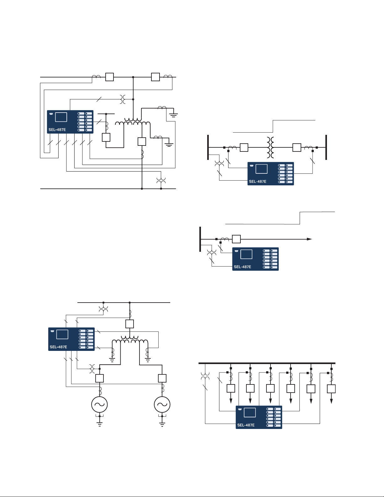
REF Protection
Apply the REF protection feature to provide sensitive detec-
tion of internal ground faults on grounded wye-connected
transformer windings and autotransformers. Use single-
phase neutral current inputs for providing neutral CT oper-
ating current for as many as three windings. Polarizing
current is derived from the residual current calculated for
the corresponding protected winding. A directional ele-
ment determines whether the fault is internal or external.
Zero-sequence current thresholds supervise tripping. The
relay can accommodate CT ratio mismatch as great as 35:1.
Figure 4 Mho Characteristics
Table 1 Supported Time-Overcurrent Curves
U.S. Curves IEC Curves
U1 (moderately inverse) C1 (standard inverse)
U2 (inverse) C2 (very inverse)
U3 (very inverse) C3 (extremely inverse)
U4 (extremely inverse) C4 (long-time inverse)
U5 (short-time inverse) C5 (short-time inverse)
Expanded
Characteristic
Steady-State
Characteristic
Relay Reach
Z
R
Z
S
X
R

Schweitzer Engineering Laboratories, Inc. SEL-487E-3, -4 Data Sheet
7
Synchronism Check
Synchronism-check elements prevent circuit breakers
from closing if the corresponding phases across the open
circuit breaker are excessively out of phase, magnitude,
or frequency. The SEL-487E synchronism-check ele-
ments selectively close circuit breaker poles under the
following criteria:
➤The systems on both sides of the open circuit
breaker are in phase (within a settable voltage
angle difference).
➤The voltages on both sides of the open circuit
breaker are healthy (within a settable voltage
magnitude window).
The synchronism-check function is available for as many
as six breakers with a user-selectable reference voltage.
Each element has a user-selectable synchronizing voltage
source and incorporates slip frequency, two levels of
maximum angle difference, and breaker close time into
the closing decision. Include the synchronism-check ele-
ment outputs in the close SELOGIC control equations to
program the relay to supervise circuit breaker closing.
Current Unbalance Elements
The current unbalance logic uses the average terminal cur-
rent to calculate the percentage difference between the
individual phase current and the terminal median current.
If the percentage difference is greater than the pickup value
setting, the phase unbalance element is asserted. To pre-
vent this element from asserting during fault conditions
and after a terminal circuit breaker has closed, the final
terminal unbalance output is supervised using current,
fault detectors, and the open-phase detection logic.
Fault Identification Logic
The purpose of the fault identification logic is to deter-
mine, on a per-terminal basis, which phase(s) was involved
in a fault for which the transformer tripped. Determining
the faulted phase is based on current inputs from wye-
connected CTs. The logic does not determine the faulted
phase for the following cases:
➤Delta-connected CTs (CTCONm= D)
➤Where only zero-sequence current flows through
the relay terminal (no negative-sequence current
and no positive-sequence current)
This logic identifies a sector in which a faulted phase(s)
can appear by comparing the angle between the negative-
and zero-sequence currents I2mand I0m(m= S, T, U, W,
X, Y).
Applications
The SEL-487E offers comprehensive transformer protec-
tion features. Around the clock winding phase compen-
sation simplifies setting the transformer protection elements.
Harmonic restraint and blocking by using second- and
fourth-harmonic quantities provide secure operation during
transformer energization, while maintaining sensitivity
for internal faults. Waveshape-based inrush detection
addresses inrush conditions that contain low second- and
fourth-harmonic content. For applications without voltage
inputs (therefore no V/Hz element), use the fifth-harmonic
monitoring to detect and alarm on overexcitation conditions.
Flexible ordering options allow either 1 A or 5 A CT inputs
for each transformer winding to configure the SEL-487E
for a variety of CT configurations.
Configure the SEL-487E for transformer differential pro-
tection for transformer applications by using as many as
six three-phase restraint current inputs. This includes sin-
gle transformers with tertiary windings. Figure 5 shows
the SEL-487E in a typical two-winding transformer
application. Use the remaining three-phase current inputs
for feeder backup protection.
Use the negative-sequence differential element for sensitive
detection of interturn faults within the transformer winding.
Phase-, negative-, and zero-sequence overcurrent elements
provide backup protection. Use breaker-failure protec-
tion with subsidence detection to detect breaker failure
and minimize system coordination times.
When voltage inputs are provided to the SEL-487E, voltage-
based protection elements and frequency tracking are
made available. Frequency tracking from 40.0 to 65.0 Hz
Figure 5 Two-Winding Transformer Application
Transformer
Differential Zone
3
3
333

SEL-487E-3, -4 Data Sheet Schweitzer Engineering Laboratories, Inc.
8
over- and undervoltage, and frequency elements, along
with V/Hz elements provide the SEL-487E with accurate
transformer protection for off-frequency events and over-
excitation conditions.
Use the SEL-487E for complete protection of generator
step-up (GSU) transformer applications. Use built-in ther-
mal elements for monitoring both generator and transformer
winding temperatures. Apply the V/Hz element with two
level settings for overexcitation protection of loaded and
unloaded generator operating conditions. Set the directional
power elements to detect forward and reverse power flow
conditions for monitoring and protection of the GSU
transformer in prime power, standby, base load, and peak
shaving applications. Figure 7 shows the SEL-487E in a
typical GSU application.
Distance Protection
The SEL-487E simultaneously supports as many as four
zones of phase and ground distance protection by using
mho or quadrilateral characteristics. You can use expanded
SELOGIC control equations to tailor the relay further to
your particular application. The SEL-487E distance ele-
ments are flexible enough to be used for transmission
line or transformer winding protection, as shown in Figure 8
and Figure 9.
Six Terminal Feeder Protection
Use the six three-phase current terminals on the SEL-487E
to provide comprehensive feeder protection and control
including overcurrent, directional overcurrent, reclosing,
and breaker failure protection for six feeders. Figure 10
shows a single SEL-487E can provide full feeder func-
tionality of six single function feeder relays thereby
reducing the device count within the system.
Figure 6 Single Transformer REF Application
Figure 7 Generator Step-Up Application
High Voltage
Low Voltage
Tertiary
REF
REF
3
3
3 31133
3
3
3 33
1
1REF REF
Figure 8 Transformer Distance Application
Figure 9 Transmission Line Distance Application
Figure 10 Six Terminal Feeder Application
5252
S
3
3
Zone 1
Zone 2
T
3
52
S
3
Zone 1
Zone 2
3
52
3
52 52 52 52
352

Schweitzer Engineering Laboratories, Inc. SEL-487E-3, -4 Data Sheet
9
Synchrophasor Applications
Use the SEL-487E as a station-wide synchrophasor mea-
surement and recording device. The SEL-487E provides
as many as 24 analog channels of synchrophasor data and
can serve as a central phasor measurement unit in any sub-
station or power generation facility. The SEL-487E can be
configured to send five unique synchrophasor data streams
over serial and Ethernet ports. Measure voltage and cur-
rent phase angle relationships at generators and trans-
formers, key source nodes for stability studies and load
angle measurements. Use the SEL-487E to store as much
as 120 seconds of IEEE C37.118 binary synchrophasor
data for all 24 analog channels at a recording rate of 60
messages per second. A SELOGIC control equation trig-
gers storage of data. Capture data as necessary, and then
store this information in SEL-487E nonvolatile memory.
Use this capability to record system transients for com-
parison to state machine estimations.
Additional Features
Front-Panel Display
The LCD shows event, metering, setting, and relay self-
test status information. The target LEDs display relay
target information as shown in Figure 12.
The LCD is controlled by the navigation pushbuttons
(Figure 13), automatic messages the relay generates, and
user-programmed analog and digital display points. The
rotating display scrolls through alarm points, display points,
and metering screens. If none are active, the relay scrolls
through displays of the fundamental and rms metering
screens. Each display remains for a user-programmed
time (1–15 s) before the display continues scrolling. Any
message the relay generates because of an alarm condition
takes precedence over the rotating display.
Figure 12 and Figure 13 show close-up views of the front
panel of the SEL-487E. The front panel includes a 128 x
128 pixel, 3" x 3" LCD screen; LED target indicators; and
pushbuttons with indicating LEDs for local control func-
tions. The asserted and deasserted colors for the LEDs
are programmable. Configure any of the direct-acting push-
buttons to navigate directly to any HMI menu item for fast
viewing of events, alarm points, display points, or the SER.
Bay Control
The SEL-487E provides dynamic bay one-line diagrams on
the front-panel screen with disconnect and breaker con-
trol capabilities for user-selectable bay types. You can
Figure 11 Station-Wide Synchrophasor Application
G
Figure 12 Factory-Default Status and Trip Target LEDs
(12 Pushbutton, 24 Target LED Option)
Figure 13 Factory-Default Front-Panel Display and
Pushbuttons
FAULT QUANTITIES
(pu)
Zone 1 Zone 2
IOPA= 4.35 0.20
IOPB= 4.76 0.12
IOPC= 0.56 0.88
IRTA= 6.65 1.09
IRTB= 6.21 1.81
IRTC= 1.06 1.25
EVENT SUMMARY 10002

SEL-487E-3, -4 Data Sheet Schweitzer Engineering Laboratories, Inc.
10
download the QuickSet interface from selinc.com to
obtain additional user-selectable bay types. The bay con-
trol can control as many as ten disconnects and two break-
ers, depending on the one-line diagram selected. Certain
one-line diagrams provide status for as many as three
breakers and five disconnect switches. Operate discon-
nects and breakers with ASCII commands, SELOGIC
control equations, Fast Operate Messages, and from the
one-line diagram. The one-line diagram includes user-
configurable apparatus labels and as many as six user-
definable analog quantities.
One-Line Bay Diagrams
The SEL-487E offers a variety of preconfigured one-line
diagrams for common bus configurations. Once you
select a one-line diagram, you can customize the names
for all of the breakers, disconnect switches, and buses.
Most one-line diagrams contain analog display points.
You can set these display points to any of the available
analog quantities (including remote 87L currents) with
labels, units, and scaling. The SEL-487E updates these
values along with the breakers and switch position in real
time to give instant status and complete control of a bay.
The following diagrams demonstrate some of the precon-
figured bay arrangements available in the SEL-487E.
Programmable interlocks help prevent operators from
incorrectly opening or closing switches or breakers. The
SEL-487E not only prevents operators from making an
incorrect control decision, but it can notify and/or alarm
upon initiation of an incorrect operation.
Circuit Breaker Operations From the
Front Panel
Figure 14–Figure 17 are examples of some of the select-
able one-line diagrams in the SEL-487E. Select the one-
line diagram from the Bay settings. Additional settings
for defining labels and analog quantities are also found in
the Bay settings. One-line diagrams are composed of the
following:
➤Bay names and bay labels
➤Busbar and busbar labels
➤Breaker and breaker labels
➤Disconnect switches and disconnect switch labels
➤Analog display points
Figure 18 shows the breaker control screens available
when the ENT pushbutton is pressed with the circuit
breaker highlighted as shown in Figure 18(a).
Figure 14 Breaker-and-a-Half
Figure 15 Ring Bus With Ground Switch
Figure 16 Double Bus/Double Breaker
Figure 17 Source Transfer Bus
BAYNAME
BK2
BK1
SW1 SW2
BK3
BAYLAB2BAYLAB1
BUSNAM1
BUSNAM2
ESCNAVIG
BAYNAME
6 ANALOGS
I:99999.9 A
V:99999.9 KV
P:99999.9 MW
Q:99999.9 MV
F:99.9 HZ
BAYLAB1
SW2
SW3
BK1
BK2
SW1
BAYLAB2
ESCNAVIG
BAYNAME
6 ANALOGS
I:99999.9 A
V:99999.9 KV
P:99999.9 MW
Q:99999.9 MV
F:99.9 HZ
BUSNAM1
SW2
SW3
BK1 BK2
SW1
BUSNAM2
ESCNAVIG
BAYNAME
BUSNAM1
BK1 BK2
BUSNAM2
BAYLAB1
I:99999.9 A
V:99999.9 KV
P:99999.9 MW
I:99999.9 A
V:99999.9 KV
P:99999.9 MW
ESCNAVIG

Schweitzer Engineering Laboratories, Inc. SEL-487E-3, -4 Data Sheet
11
Rack-Type Breakers Mosaics
The SEL-487E supports the display of rack-type (also
referred to as truck-type) circuit breakers. The rack-type
breakers have three positions: racked out, test, and racked
in. When in the test or racked-in positions, the breaker
can be displayed as open or closed. When racked out, no
breaker open/close display are available. The rack-type
breakers are a display-only functionality and do not impact
any circuit breaker control capabilities.
Status and Trip Target LEDs
The SEL-487E includes programmable status and trip tar-
get LEDs, as well as programmable direct-action control
pushbuttons on the front panel. Figure 12 shows these targets.
The SEL-487E features a versatile front panel that you
can customize to fit your needs. Use SELOGIC control
equations and slide-in configurable front-panel labels to
change the function and identification of target LEDs
and operator control pushbuttons and LEDs. The blank
slide-in label set is included with the SEL-487E. You can
use templates supplied with the relay or hand label sup-
plied blank labels and print label sets from a printer.
Alarm Points
You can display messages on the SEL-487E front-panel
LCD that indicate alarm conditions in the power system.
The relay uses alarm points to place these messages on
the LCD.
Figure 19 shows a sample alarm points screen. The relay
can display as many as 66 alarm points. The relay auto-
matically displays new alarm points while in manual-
scrolling mode and in autoscrolling mode. You can con-
figure the alarm points message and trigger it either
immediately by using inputs, communications, or condi-
tionally by using powerful SELOGIC control equations.
The asterisk next to the alarm point indicates an active
alarm. Use the front-panel navigation pushbuttons to
clear inactive alarms.
Figure 18 Screens for Circuit Breaker Selection
Bus Labels
BAYNAME
BAYNAME
OPEN BREAKER
CLOSE BREAKER
OPEN
Bkrnam
PRESS TO ACTIVATE
Bay not in
LOCAL Control!
Cannot issue
controls.
Press ENT with breaker highlighted
Breaker
Highlighted
(a) Bay Screen
(c) LOCAL bit NOT asserted
(b) Breaker Control Screen
After three seconds,
re-display the previous screen
BUS 2
Dis 4
Bkr 1
Dis 3
Dis 1 Dis 2
BUS 1
BUS T
Bay Name
Disconnect
Switch Label
Disconnect
Switch Label
Disconnect
Switch Label
Analog
Quantities
Display
Breaker
Label
6 ANALOGS
I:99999.9 A
V:99999.9 KV
P:99999.9 MW
Q:99999.9 MV
F:60.000 HZ
ESCNAVIG
ESCNAVIG

SEL-487E-3, -4 Data Sheet Schweitzer Engineering Laboratories, Inc.
12
Advanced Display Points
Create custom screens showing metering values, special
text messages, or a mix of analog and status information.
Figure 20 shows an example of how you can use display
points to show circuit breaker information and current
metering. You can create as many as 96 display points.
All display points occupy only one line on the display at
all times. The height of the line is programmable as either
single or double, as shown in Figure 20. These screens
become part of the autoscrolling display when the front
panel times out.
Communications Features
See Specifications on page 25 for specific supported protocols.
The relay offers the following communications features:
➤Four independent EIA-232 serial ports.
➤Access to event history, relay status, and meter
information from the communications ports.
➤Password-controlled settings management and
automation features.
➤SCADA interface capability, including FTP,
IEC 61850, DNP3 LAN/WAN (via Ethernet), and
DNP3 (via serial port). The relay does not require
special communications software. You only need
ASCII terminals, printing terminals, or a computer
supplied with terminal emulation and a serial
communications port.
➤Synchrophasor data at 60 message-per-second data
format.
Ethernet Card
Use popular Telnet applications for easy terminal com-
munications with SEL relays and other devices. Transfer
data at high speeds for fast file uploads. The Ethernet
card communicates using FTP applications for easy and
fast file transfers.
Communicate with SCADA by DNP3 and other substa-
tion IEDs by using IEC 61850 Manufacturing Message
Specification (MMS) and GOOSE messaging.
Choose Ethernet connection media options for primary
and standby connections:
➤10/100BASE-T twisted pair network
➤100BASE FX fiber-optic network
Figure 19 Sample Alarm Points Screen
*Unauthorized Access
*LOP Asserted
*SF6 Low Bk1
ALARM POINTS
Press to acknldge
Figure 20 Sample Display Points Screen
Circuit Breaker 1
--Closed--
DISPLAY POINTS
Circuit BK1 SF6 Gas
--Alarm--
Circuit Breaker 2
A PH= 119.6 A pri
SF6 ALARM
Figure 21 System Functional Overview
Automation
Over Ethernet:
Two Ethernet Ports
10/100BASE-T
100BASE-FX
To Remote SEL Relay
Using MIRRORED BITS
Spare
Front Port Local
Operator or
Engineering
Access
IEC 61850 or
DNP LAN/WAN Communications
Processor
Serial Communication:
Three Rear EIA-232 Ports
One Front EIA-232 Port

Schweitzer Engineering Laboratories, Inc. SEL-487E-3, -4 Data Sheet
13
Telnet and FTP
Use Telnet to access relay settings, metering, and event
reports remotely by using the ASCII interface. Use FTP
to transfer settings files to and from the relay via the
high-speed Ethernet port.
DNP3 LAN/WAN
DNP3 LAN/WAN provides the relay with DNP3 Level 2
Outstation functionality over Ethernet. Configure DNP3
data maps for use with specific DNP3 masters.
PTP
The Ethernet card provides the ability for the relay to accept
IEEE 1588 PTPv2 for data time synchronization. PTP
support includes the Default, Power System, and Power
Utility Automation Profiles. When connected directly to
a grandmaster clock providing PTP at 1-second synchro-
nization intervals, the relay can be synchronized to an
accuracy of ±100 ns in the PTP time scale.
SNTP Time Synchronization
Use SNTP to synchronize relays to as little as ±1 ms with
no time source delay. Use SNTP as a primary time source,
or as a backup to a higher accuracy time input to the relay.
PRP
Use PRP to provide seamless recovery from any single
Ethernet network failure, in accordance with IEC 62439-3.
The Ethernet network and all traffic are fully duplicated
with both copies operating in parallel.
HTTP Web Server
The relay can serve read-only webpages displaying cer-
tain settings, metering, and status reports. The web server
also allows quick and secure firmware upgrades over
Ethernet. As many as four users can access the embedded
HTTP server simultaneously.
IEC 61850 Ethernet Communications
IEC 61850 Ethernet-based communication protocols
provide interoperability between intelligent devices within
the substation. Standardized logical nodes allow inter-
connection of intelligent devices from different manufac-
turers for monitoring and control of the substation.
Eliminate system RTUs by streaming monitor and con-
trol information from the intelligent devices directly to
remote SCADA client devices.
You can order the relay with IEC 61850 protocol for relay
monitor and control functions, including:
➤As many as 128 incoming GOOSE messages. You
can use the incoming GOOSE messages to control
as many as 256 control bits in the relay with <3 ms
latency from device to device depending on network
design. These messages provide binary control
inputs to the relay for high-speed control functions
and monitoring.
➤As many as eight outgoing GOOSE messages.
Configure outgoing GOOSE messages for Boolean
or analog data such as high-speed control and
monitoring of external breakers, switches, and other
devices. Boolean data are provided with <3 ms latency
from device to device depending on network design.
➤IEC 61850 Data Server. The relay equipped with
embedded IEC 61850 Ethernet protocol provides
data according to predefined logical node objects.
Each relay supports as many as seven unbuffered
MMS report client associations. Relevant Relay
Word bits are available within the logical node
data, so status of relay elements, inputs, outputs, or
SELOGIC control equations can be monitored.
➤As many as 256 virtual bits. Configure the virtual
bits within GOOSE messaging to represent a variety
of Boolean values available within the relay. These
bits that the relay receives are available for use in
SELOGIC control equations.
➤As many as 64 remote analog outputs. Assign the
remote analog outputs to virtually any analog quantity
available in the relay. You can also use SELOGIC
math variables to develop custom analog quantities
for assignment as remote analog outputs. Remote
Figure 22 Example PTP Network
GPS

SEL-487E-3, -4 Data Sheet Schweitzer Engineering Laboratories, Inc.
14
analog outputs that use GOOSE messages provide
peer-to-peer transmission of analog data. Each relay
can receive as many as 256 remote analog inputs
and use those inputs as analog quantities within
SELOGIC control equations.
➤IEC 61850 standard operating modes. The relay
supports Test, Blocked, On, and Off. The relay also
supports Simulation mode for added flexibility.
MMS File Services
This service of IEC 61850 MMS provides support for file
transfers completely within an MMS session. All relay
files that can be transferred via FTP can also be transferred
via MMS file services.
MMS Authentication
When enabled via a setting in the Configured IED Descrip-
tion (CID) file, the relay requires authentication from any
client requesting to initiate an MMS session.
Architect Software
Use ACSELERATOR Architect SEL-5032 Software to
manage the IEC 61850 configuration for devices on the
network. This Windows-based software provides easy-
to-use displays for identifying and binding IEC 61850
network data among logical nodes that use IEC 61850-
compliant CID files. Architect uses CID files to describe
the data available in each relay.
Serial Communications
MIRRORED BITS Communications
The SEL patented MIRRORED BITS technology provides
bidirectional relay-to-relay digital communication.
Figure 23 shows two relays with SEL-2815 Fiber-Optic
Transceivers that use MIRRORED BITS communications.
MIRRORED BITS communications can operate simultane-
ously on any two serial ports. This bidirectional digital
communication creates additional outputs (transmitted
MIRRORED BITS) and additional inputs (received
MIRRORED BITS) for each serial port operating in the
MIRRORED BITS communications mode.
Communicated information can include digital, analog,
and virtual terminal data. Virtual terminal allows opera-
tor access to remote relays through the local relay. You
can use this MIRRORED BITS protocol to transfer infor-
mation between stations to enhance coordination and
achieve faster tripping.
Open Communications Protocols
The relay does not require special communications software. ASCII terminals, printing terminals, or a computer sup-
plied with terminal emulation and a serial communications port are all that is required. Table 2 lists a brief description of
the terminal protocols.
Figure 23 Integral Communication Provides Secure Protection, Monitoring, and Control as Well as Terminal Access to
Both Relays Through One Connection
HV Breaker
MIRRORED BITS Communications
HV Busbars LV Busbars
Remote
LV Breaker
Power
Cable
Table 2 Open Communications Protocol (Sheet 1 of 2)
Type Description
ASCII Plain-language commands for human and simple machine communications. Use for metering, setting, self-test
status, event reporting, and other functions.
Compressed ASCII Comma-delimited ASCII data reports. Allows external devices to obtain bay data in an appropriate format for
direct import into spreadsheets and database programs. Data are checksum protected.
Extended Fast Meter, Fast
Operate, and Fast SER
Binary protocol for machine-to-machine communications. Quickly updates SEL-2032 Communications Pro-
cessors, RTUs, and other substation devices with metering information, bay element, I/O status, time-tags,
open and close commands, and summary event reports. Data are checksum protected. Binary and ASCII proto-
cols operate simultaneously over the same communications lines so that control operator metering information
is not lost while a technician is transferring an event report.

Schweitzer Engineering Laboratories, Inc. SEL-487E-3, -4 Data Sheet
15
Automation
Flexible Control Logic and
Integration Features
Use the control logic to perform the following:
➤Replace traditional panel control switches
➤Eliminate remote terminal unit (RTU)-to-bay wiring
➤Replace traditional latching relays
➤Replace traditional indicating panel lights
Eliminate traditional panel control switches with 96 local
control points. Set, clear, or pulse local control points
with the front-panel pushbuttons and display. Program
the local control points to implement your control scheme
via SELOGIC control equations. Use the local control
points for such functions as trip testing, enabling/disabling
reclosing, and tripping/closing circuit breakers.
Eliminate RTU-to-bay wiring with 64 remote control
points per relay. Set, clear, or pulse remote control points
via serial port commands. Incorporate the remote control
points into your control scheme via SELOGIC control
equations. Use remote control points for SCADA-type
control operations (e.g., trip, close, settings group selection).
Replace traditional latching relays for such functions as
remote control enable with 64 latching control points.
Program latch set and latch reset conditions with SELOGIC
control equations. Set or reset the latch control points via
control inputs, remote control points, local control points,
or any programmable logic condition. The relay retains
the states of the latch control points after turning on fol-
lowing a power interruption.
Replace traditional indicating panel lights and switches
with as many as 24 latching target LEDs and as many as
12 programmable pushbuttons with LEDs. Define cus-
tom messages (i.e., BREAKER OPEN, BREAKER CLOSED,
RECLOSER ENABLED) to report power system or relay con-
ditions on the large format LCD. Control displayed mes-
sages with SELOGIC control equations by driving the
LCD via any logic point in the relay.
SELOGIC Control Equations With
Expanded Capabilities and Aliases
Expanded SELOGIC control equations put relay logic in
the hands of the engineer. Assign inputs to suit your
application, logically combine selected bay elements for
various control functions, and assign outputs to your
logic functions.
Programming SELOGIC control equations consists of
combining relay elements, inputs, and outputs with
SELOGIC control equation operators (Table 3). Any ele-
ment in the Relay Word can be used in these equations.
For complex or unique applications, these expanded
SELOGIC functions allow superior flexibility.
Ymodem Support for reading event, settings, and oscillography files.
Optional DNP3 Level 2
Outstation
DNP with point remapping. Includes access to metering data, protection elements, contact I/O, targets, SER,
relay summary event reports, and settings groups.
IEEE C37.118 Phasor measurement protocol.
MIRRORED BITS SEL protocol for exchanging digital and analog information among SEL relays and for use as low-speed termi-
nal connection.
IEC 61850 Ethernet-based international standard for interoperability between intelligent devices in a substation.
PRP PRP provides redundant Ethernet network capabilities for seamless operation in the event of loss to one network.
SNTP Ethernet-based SNTP for time synchronization among relays.
FTP and Telnet Use Telnet to establish a terminal-to-relay connection over Ethernet. Use FTP to move files in and out of the
relay over Ethernet.
Table 2 Open Communications Protocol (Sheet 2 of 2)
Type Description
Table 3 SELOGIC Control Equation Operators (Sheet 1 of 2)
Operator Type Operators Comments
Boolean AND, OR, NOT Allows combination of measuring units.
Edge Detection F_TRIG, R_TRIG Operates at the change of state of an internal function.
Comparison >, , =, <=, <, < >
Arithmetic +, –, *, / Uses traditional math functions for analog quantities in an easily programmable equation.

SEL-487E-3, -4 Data Sheet Schweitzer Engineering Laboratories, Inc.
16
Use the relay alias capability to assign more meaningful
names to analog and Boolean quantities. This improves
the readability of customized programming. Use as many
as 200 aliases to rename any digital or analog quantity.
The following is an example of possible applications of
SELOGIC control equations that use aliases.
Add programmable control functions to your relay and
automation systems. New functions and capabilities enable
using analog values in conditional logic statements. The
following are examples of possible applications of
SELOGIC control equations with expanded capabilities.
➤Emulate a motor-driven reclose timer, including
stall, reset, and drive-to-lockout conditions.
➤Scale analog values for SCADA retrieval.
➤Initiate remedial action sequence based on load
flow before fault conditions.
➤Interlock breakers and disconnect switches.
➤Restrict breaker tripping in excessive duty
situations without additional relays.
➤Hold momentary change-of-state conditions for
SCADA polling.
Metering and Monitoring
Access a range of useful information in the relay with the
metering function. Metered quantities include fundamen-
tal primary and secondary current and voltage magni-
tudes and angles for each terminal. RMS voltage and
current metering is also provided. Fundamental phase
and real and reactive power, per-phase voltage magni-
tude, angle, and frequency are displayed in the metering
report for applications that use the relay voltage inputs.
Numerical ABS, SIN, COS, LN, EXP,
SQRT, LOG
Precedence Control ( ) Allows multiple and nested sets of parentheses.
Comment #, (* *) Provides for easy documentation of control and protection logic.
Table 3 SELOGIC Control Equation Operators (Sheet 2 of 2)
Operator Type Operators Comments
=>>SET T <Enter>
1: PMV01,THETA
(assign the alias “THETA” to math variable PMV01)
2: PMV02,TAN
(assign the alias “TAN” to math variable PMV02)
=>>SET L <Enter>
1: # CALCULATE THE TANGENT OF THETA
2: TAN:=SIN(THETA)/COS(THETA)
(use the aliases in an equation)
Table 4 Metering Capabilities (Sheet 1 of 2)
Capabilities Description
Instantaneous Quantities
Voltages
VA, B, C (V, Z), V3V0, V1, 3V2
Voltages measured at the fundamental frequency of the power system. The relay com-
pensates for delta-connected CTs when reporting primary values.
RMS Voltages
VA, B, C (V, Z), V
RMS voltages include fundamental plus all measurable harmonics.
Compensated Fundamental Currents
IA, B, C (S, T, U, W, X, Y), 3I0, I1, 3I2
IA, B, C (ST, TU, UW, WX), 3I0, I1, 3I2
Currents measured at the fundamental frequency of the power system with transformer
phase-compensation applied.
RMS Currents
IA, B, C (S, T, U, W, X, Y)
IA, B, C (ST, TU, UW, WX)
RMS currents include fundamental plus all measurable harmonics.

Schweitzer Engineering Laboratories, Inc. SEL-487E-3, -4 Data Sheet
17
Event Reporting and SER
Event reports and SER features simplify post-fault analy-
sis and help improve your understanding of both simple
and complex protective scheme operations. These fea-
tures also aid in testing and troubleshooting relay settings
and protective schemes.
Oscillography and Event Reporting
In response to a user-selected internal or external trigger,
the voltage, current, and element status information con-
tained in each event report confirms relay, scheme, and
system performance for every fault. The relay provides
sampling rates as fast as 8 kHz for analog quantities in a
COMTRADE file format, as well as eight-sample-per-
cycle and four-sample-per-cycle event reports. The relay
stores as much as 3 seconds of 8 kHz event data. The
relay supports inclusion of user-configurable analogs in
the events. Reports are stored in nonvolatile memory.
Relay settings operational in the relay at the time of the
event are appended to each event report.
Each relay provides event reports for analysis with soft-
ware such as SEL-5601-2 SYNCHROWAVE®Event Soft-
ware. With SYNCHROWAVEEvent, you can display
events from several relays to make the fault analysis eas-
ier and more meaningful. Because the different relays
time-stamp the events with values from their individual
clocks, be sure to time synchronize the relay with an
IRIG-B clock input or PTP source to use this feature.
Event Summary
Each time the relay generates a standard event report, it
also generates a corresponding event summary. This is a
concise description of an event that includes the follow-
ing information:
➤Relay/terminal identification
➤Event date and time
➤Event type
➤Event number
➤Time source
➤Active settings group
Differential Metering
Currents
IA, B, C, I1, 3I2, 3I0
Local terminal/all
Remote Terminals
Differential Current
IA, B, C, I1, 3I2, 3I0
Local terminal/all
Remote terminals
Alpha Plane
k
alpha
Alpha plane ratio
Alpha plane angle
Power/Energy Metering Quantities
Fundamental Power Quantities
SA, B, C, PA, B, C, QA, B, C (S, T, U, W, X, Y)
SA, B, C, PA, B, C, QA, B, C (ST, TU, UW, WX)
S3, P3, Q3(S, T, U, W, X, Y)
S3, P3, Q3(ST, TU, UW, WX)
Power quantities calculated using fundamental voltage and current measurements;
S = MVA, P = MW, Q = MVAR.
Differential Metering
Differential
IOPA, IOPB, IOPC, IRTA, IRTB, IRTC
IOPA2, IOPB2, IOPC2, IRTA2, IRTB2,
IRTC2
IOP, Zone 1 operate current magnitude (per unit).
IRT, Zone 1 restraint current magnitude (per unit).
IOP2, Zone 2 operate current magnitude (per unit).
IRT2, Zone 2 restraint current magnitude (per unit).
Harmonics
2nd: IOPAF2, IOPBF2, IOPCF2
4th: IOPAF4, IOPBF4, IOPCF4
5th: IOPAF5, IOPBF5, IOPCF5
Zone 1 differential harmonic quantities represent the effective harmonic content of the
operate current. This content is what the relay uses for harmonic blocking and harmonic
restraint.
Demand/Peak Demand Metering
IA, B, C, 3I2, 3I0 (S, T, U, W, X, Y)
IA, B, C, 3I2, 3I0 (ST, TU, UW, WX)
IMAX (S, T, U, W, X, Y)
IMAX (ST, TU, UW, WX)
Thermal or rolling interval demand.
Table 4 Metering Capabilities (Sheet 2 of 2)
Capabilities Description

SEL-487E-3, -4 Data Sheet Schweitzer Engineering Laboratories, Inc.
18
➤Targets asserted during the fault
➤Current magnitudes and angles for each terminal
➤Voltage magnitudes and angles
➤Differential operate and restraint current
magnitudes
➤Breaker status (open/close)
With an appropriate setting, the relay sends an event
summary in ASCII text automatically to one or more
serial ports each time an event report is triggered.
SER
Use this feature to gain a broad perspective of relay ele-
ment operation. Items that trigger an SER entry are select-
able and can include as many as 250 monitoring points,
such as I/O change-of-state and element pickup/dropout.
The relay SER stores the latest 1000 events.
Analog Signal Profiling
The relay provides analog signal profiling for as many as
20 analog quantities. Select any analog quantity mea-
sured or calculated by the relay for analog signal profil-
ing. You can select signal sampling rates of 1, 5, 15, 30,
and 60 minutes through settings. The analog signal pro-
file report provides a comma-separated variable (CSV)
list that you can load into any spreadsheet or database for
analysis and graphical display.
SELOGIC enable/disable functions can start and stop signal
profiling based on Boolean or analog comparison conditions.
Substation Battery Monitor for DC
Quality Assurance
The relay measures and reports the substation battery
voltage for up to two battery systems. The SEL-411L,
SEL-421, SEL-451 support two battery monitors while
the SEL-487B, SEL-487E, and SEL-487V support one.
Each battery monitor supports programmable threshold
comparators and associated logic provides alarm and
control for batteries and chargers. The relay also pro-
vides dual ground detection. Monitor dc system status
alarms with an SEL communications processor and trig-
ger messages, telephone calls, or other actions.
The measured dc voltage is reported in the METER display
via serial port communications, on the LCD, and in the
event report. Use the event report data to see an oscillo-
graphic display of the battery voltage. Monitor the sub-
station battery voltage drops during trip, close, and other
control operations.
Breaker Contact Wear Monitoring
Circuit breakers experience mechanical and electrical wear
during each operation. Effective scheduling of breaker
maintenance takes into account the manufacturer’s pub-
lished data of contact wear versus interruption levels and
operation count.
➤Every time the breaker trips, the relay integrates
interrupted current. When the result of this integration
exceeds the threshold set by the breaker wear curve
(Figure 24), the relay can alarm via an output contact
or the optional front-panel display. With this
information, you can schedule breaker maintenance
in a timely, economical fashion.
➤The relay monitors last and average mechanical and
electrical interruption time per pole. You can easily
determine if operating time is increasing beyond
reasonable tolerance and then schedule proactive
breaker maintenance. You can activate an alarm
point if operation time exceeds a preset value.
The relay also monitors breaker motor run time, pole dis-
crepancy, and breaker inactivity.
Transformer Thermal Monitoring
Transformer thermal monitoring for mineral-oil immersed
transformers is a standard feature in the SEL-487E. Spec-
ify the SEL-487E to provide this capability for monitor-
ing and protection of a single three-phase transformer, as
well as for monitoring and protection of three independent
single-phase units. Use the thermal element to activate a
control action or issue a warning or alarm when your trans-
former overheats or is in danger of excessive insulation
aging or loss of life.
The thermal element operates in one of three modes, depend-
ing upon the presence or lack of measured temperature
inputs: 1) measured ambient and top-oil temperature inputs,
2) measured ambient temperature only, and 3) no mea-
sured temperature inputs. If the relay receives measured
ambient and top-oil temperatures, the thermal element
calculates hot-spot temperature. When the relay receives
a measurement of ambient temperature without top-oil
Figure 24 Breaker Contact Wear Curve and Settings
kA Interrupted
(Set Point 1)
(Set Point 2)
(Set Point 3)
Breaker Manufacturer's
Maintenance Curve
Close to Open Operations

Schweitzer Engineering Laboratories, Inc. SEL-487E-3, -4 Data Sheet
19
temperature, the thermal element calculates the top-oil
temperature and hot-spot temperature. In the absence of
any measured ambient or top-oil temperatures, the ther-
mal element uses a default ambient temperature setting
that you select and calculates the top-oil and hot-spot tem-
peratures. The relay uses hot-spot temperature as a basis
for calculating the insulation aging acceleration factor
(FAA) and loss-of-life quantities. Use the thermal element
to indicate alarm conditions and/or activate control actions
when one or more of the following exceed settable limits:
➤Top-oil temperature
➤Winding hot-spot temperature
➤Insulation FAA
➤Daily loss-of-life
➤Total loss-of-life
Generate a thermal monitor report that indicates the pres-
ent thermal status of the transformer. Historical thermal
event reports and profile data are stored in the relay in
hourly format for the previous 24 hours and in daily for-
mat for the previous 31 days.
Through-Fault Event Monitor
A through fault is an overcurrent event external to the
differential protection zone. Though a through fault is
not an in-zone event, the currents required to feed this
external fault can cause great stress on the apparatus inside
the differential protection zone. Through-fault currents
can cause transformer winding displacement leading to
mechanical damage and increased transformer thermal
wear because of mechanical stress of insulation compo-
nents in the transformer. The SEL-487E through-fault
event monitor gathers current level, duration, and date/
time for each through fault. The monitor also calculates a
I2t and cumulatively stores these data per phase. The
SEL-487E through-fault report also provides percent of
total through-fault accumulated according to the IEEE
Guide for Liquid-Immersed Transformer Through-Fault-
Current Duration, IEEE C57.109-1993. Use through-
fault event data to schedule proactive transformer bank
maintenance and help justify through-fault mitigation
efforts. Apply the accumulated I2t alarm capability of the
relay to indicate excess through-fault current over time.
Diagrams and Dimensions
Figure 25 Typical One-Line Diagram for Collecting Transformer Temperature Data
Top-Oil Temperature (RTD)
Ambient
Temperature
RTD
Figure 26 5U Front Panel, Rack-Mount Option
Opening
i7116e
TRIP
BREAKER
T01
ENABLE
DIRECTIONAL
OVER
CURRENT
RESET
BREAKER
WEAR
LEVELS
TRIP
BREAKER
S01
CLOSE
BREAKER
T01
EVENT
SUMMARY
ENABLE
ADAPTIVE
OVER
CURRENT
CLOSE
BREAKER
S01
VAV ON
T BRKR FAIL
REF
S BRKR FAIL
C PH DIFF
LOP V
THRU-FAULT
ALARM
B PH DIFF
TRIP T
A PH DI FF
TRIP S
COMMS
ALARM
HARM BLOCK
DIRECTIONAL
POWER
VCV ON
VBV ON
O/U FREQ
VOLTS/Hz
O/U VOLTAGE
OVER
CURRENT
FREQ OK
EXTERNAL
FAULT
IRIG OK
INSULATION
ALARM
TRIP
ENABLED TAR G E T
RESET
ENT
ESC
SEL–487E
SCHWEITZER
ENGINEERING
LABORATORIES
PORT F

SEL-487E-3, -4 Data Sheet Schweitzer Engineering Laboratories, Inc.
20
Figure 27 6U Front Panel, Panel-Mount Option
Figure 28 5U Rear Panel, Main Board, LEA Voltage Option
i7081g
TRIP
BREAKER
T01
ENABLE
DIRECTIONAL
OVER
CURRENT
RESET
BREAKER
WEAR
LEVELS
TRIP
BREAKER
S01
CLOSE
BREAKER
T01
EVENT
SUMMARY
ENABLE
ADAPTIVE
OVER
CURRENT
CLOSE
BREAKER
S01
VAV ON
T BRKR FAIL
REF
S BRKR FAIL
C PH DIFF
LOP V
THRU-FAULT
ALARM
B PH DIFF
TRIP T
A PH DIFF
TRIP S
COMMS
ALARM
HARM BLOCK
DIRECTIONAL
POWER
VCV ON
VBV ON
O/U FREQ
VOLTS/Hz
O/U VOLTAGE
OVER
CURRENT
FREQ OK
EXTERNAL
FAULT
IRIG OK
INSULATION
ALARM
TRIP
ENABLED TAR G E T
RESET
ENT
ESC
SEL–487E
SCHWEITZER
ENGINEERING
LABORATORIES
PORT F
31
GND
26 28 30
25 27 29
POWER
/H /N
+—
MONITOR
Vdc 1
+—
Y01 02 03 04 05 06 07 08 09 10 11 12 13 14 15 16 17 18
CSBSAS CTBTAT CUBUAU
PORT 5DPORT 5CPORT 5BPORT 5A
LINK = YELLOW
ACTIVITY = GREEN
1
9
1
9
1
9
PORT 3PORT 2PORT 1
EIA–232 PORTS
IRIG-B
TIME
OUT01 OUT06OUT02 OUT03 OUT04 OUT05 OUT07 IN01 IN02 IN03 IN04 IN05 IN06 IN07OUT08
32
31
30
29
28
27
26
25
24
23
22
21
20
19
18
17
16
15
14
13
12
11
10
09
08
07
06
05
04
03
02
01
100
A
100
A
+++
Y
196–1734.A
19 20 21 22 23 24 NCNC
VCVVBV
VAV
196–1747.A
ICY
IY3
IBY
IY2
IAY
IY1
Z Z
01 02 03 04 05 06 07 08 09 10 11 12 13 14 15 16 17 18 19 20 21 22 23 24 NCNC
VCZVBZ
VAZ
ICWIBWIAW ICXIBXIAX
This manual suits for next models
1
Table of contents
Other Sel Relay manuals