Sel SEL-2664S User manual

Schweitzer Engineering Laboratories, Inc. SEL- 2664S Data Sheet
100% Stator Ground Fault Protection
100% of the Time
Major Features and Benefits
The SEL-2664S Stator Ground Protection Relay provides an exceptional combination of protection, metering, monitor-
ing, control, and communications in a compact industrial package.
➤Standard Protection and Control Features. Protect your generator against stator insulation degradation and
ground faults, and monitor the neutral grounding resistor. When used with an SEL-2664 Field Ground Module,
the SEL-2664S Relay protects against rotor field insulation faults to ground. The stator ground protection works
for 100 percent of the stator winding and for all operating conditions, including when the generator is starting,
ramping, or offline using a novel multifrequency injection method in conjunction with the neutral overvoltage
elements.
➤Operator Controls. Take advantage of multiple methods for accessing and using the operator interface of the
relay. The front and side panels have eight LEDs that indicate the ENABLED, TRIP, WARNING, 64S, 64F, 59N, 64F
MODULE FAIL, 64S INJECT ON status of the relay. The front panel also provides a TARGET RESET pushbutton for reset-
ting the relay and the targets.
➤Relay and Logic Settings Software. Use ACSELERATOR QuickSet®SEL-5030 Software to reduce your
engineering costs for relay settings and logic programming and simplify development of SELOGIC®control
equations.
➤Metering and Monitoring. Use built-in metering functions to eliminate separately mounted metering devices.
Analyze SER reports and oscillographic event reports for rapid commissioning, testing, and post-fault
diagnostics. Additional monitoring functions include the Profile Report.
➤Control Inputs and Outputs. Take advantage of two internally wetted control inputs and four contact outputs
(one Form C and three Form A) for control and status indication.
SEL-2664S
Stator Ground Protection Relay

SEL- 2664S Data Sheet Schweitzer Engineering Laboratories, Inc.
2
➤Communications Ports.
➣Port 1 with dual fiber-optic Ethernet ports
➣Port 2 with an ST®fiber-optic EIA-232 serial port
➣Front port and Port 3 with an EIA-232 configurable serial port
➤Communications Protocols.
➣Modbus®RTU, Modbus TCP/IP
➣DNP3 serial and LAN/WAN
➣IEC 61850
➣Simple Network Time Protocol (SNTP)
➣File Transfer Protocol (FTP)
➣Telnet (SEL ASCII)
➣SEL protocols, including MIRRORED BITS®communications
➤Conformally Coated.
Overview
Figure 1 Functional Diagram
Operator
Interface
HMI
LGC
SELOGIC
DFR
Event
Reports
LDP
Profile
Report
Monitoring
SER
Sequential
Events
Recorder
64F
Metering
MET
Field
Ground
IN
VN
DC Field
Excitation
NGR*
NGT‡
NGR
NGR
Open/Short
59N1
Neutral
Fundamental
Overvoltage
59N
RMS
Neutral
RMS
Overvoltage
64S
Stator
Ground
* Neutral Grounding Resistor
‡ Neutral Grounding Transformer

Schweitzer Engineering Laboratories, Inc. SEL- 2664S Data Sheet
3
Protection and Control Features
➤Stator Insulation Protection. The 64S element of
the SEL-2664S uses multisine signal injection at
generator neutral to monitor 100 percent of the sta-
tor insulation. The element works with the genera-
tor in- or out-of-service, including the generator
ramp up, with no blind period. Two levels of 64S
elements provide warning and trip along with delay
and torque control settings. The 64S elements
require neutral voltage below an allowable injection
voltage level and, together with the 59N elements
described later, provide 100 percent stator ground
protection 100 percent of the time.
➤Rotor Field Ground Protection. An SEL-2664S
Relay connected to an SEL-2664 Field Ground
Module detects field ground faults by measuring
field insulation-to-ground resistance with the
switched dc voltage injection method. Two-level
protection for warning and trip functions along with
delay and torque control settings is provided. The
module transmits the insulation resistance value to
the relay through a fiber-optic cable with ST
connectors.
➤Neutral Overvoltage Protection. The SEL-2664S
provides two neutral overvoltage elements. The
59N1 element uses the fundamental frequency
magnitude of neutral voltage (VN), and the
59NRMS element uses the rms magnitude of VN.
The relay provides one level from each of the 59N1
and 59NRMS elements for trip, along with delay
and torque control settings. The 59N elements are
independent of the 64S elements described previ-
ously. The combination of the two, with their over-
lapping coverage, provides 100 percent stator
winding protection 100 percent of the time.
➤Neutral Ground Resistor Monitor. The SEL-2664S
monitors the generator neutral grounding resistor
(NGR) value using NGR elements and operates
when a short or an open circuit is detected.
Figure 2 SEL-2664S Multisine Injection Signal
Waveform
Metering and Monitoring
Metering Functions
The SEL-2664S provides metering for neutral voltage
and current. The relay meters injection source currents
and voltages, stator insulation resistance and capacitance,
and neutral ground resistance. The relay also meters field
insulation resistance when used with the SEL-2664 Field
Ground Module. Refer to Table 1 for detailed
descriptions.
Table 1 Metered Quantities (Sheet 1 of 2)
Quantities Description
Stator Insulation (k) Resistance of the stator insulation to ground in kilohms, primary
Stator Insulation (uF) Capacitance of the stator insulation to ground in microfarads, primary
Neutral Ground Resistor () Resistance of the neutral grounding resistor in ohms (secondary or primary based on NGR
location)
Field Insulation (k) Resistance of field insulation to ground in kilohms
Neutral Voltage (V sec) Magnitude of fundamental, third-harmonic, and rms neutral voltage in secondary volts
Neutral Current (A sec)abRMS and third-harmonic magnitudes of neutral currents in secondary amperes
Neutral Current (A pri)aRMS and third-harmonic magnitudes of neutral currents in primary amperes
Injected Current (A sec)aRMS magnitude of injected current in secondary amperes
Injected Voltages (V at NGR Tap) Voltage magnitude of specific frequency at the NGR Tap

SEL- 2664S Data Sheet Schweitzer Engineering Laboratories, Inc.
4
Profile Report Monitoring
Profile report monitoring provides a periodic snapshot
(selectable rate of every 1, 5, 15, 30, or 60 minutes) of as
many as 17 selectable analog quantities from the
complete list of analog quantities the SEL-2664S
generates. Examples of analog quantities available
include the following:
➤Stator insulation resistance
➤Injected rms current
➤Neutral ground resistance
➤Third-harmonic neutral voltage
When used with the SEL-2664 Field Ground Module, the
relay can also record the field insulation resistance.
The SEL-2664S maintains profile information in a
nonvolatile buffer memory. The memory can hold data for
9800 time-stamped entries.
Automation
Flexible Control Logic and Integration Features
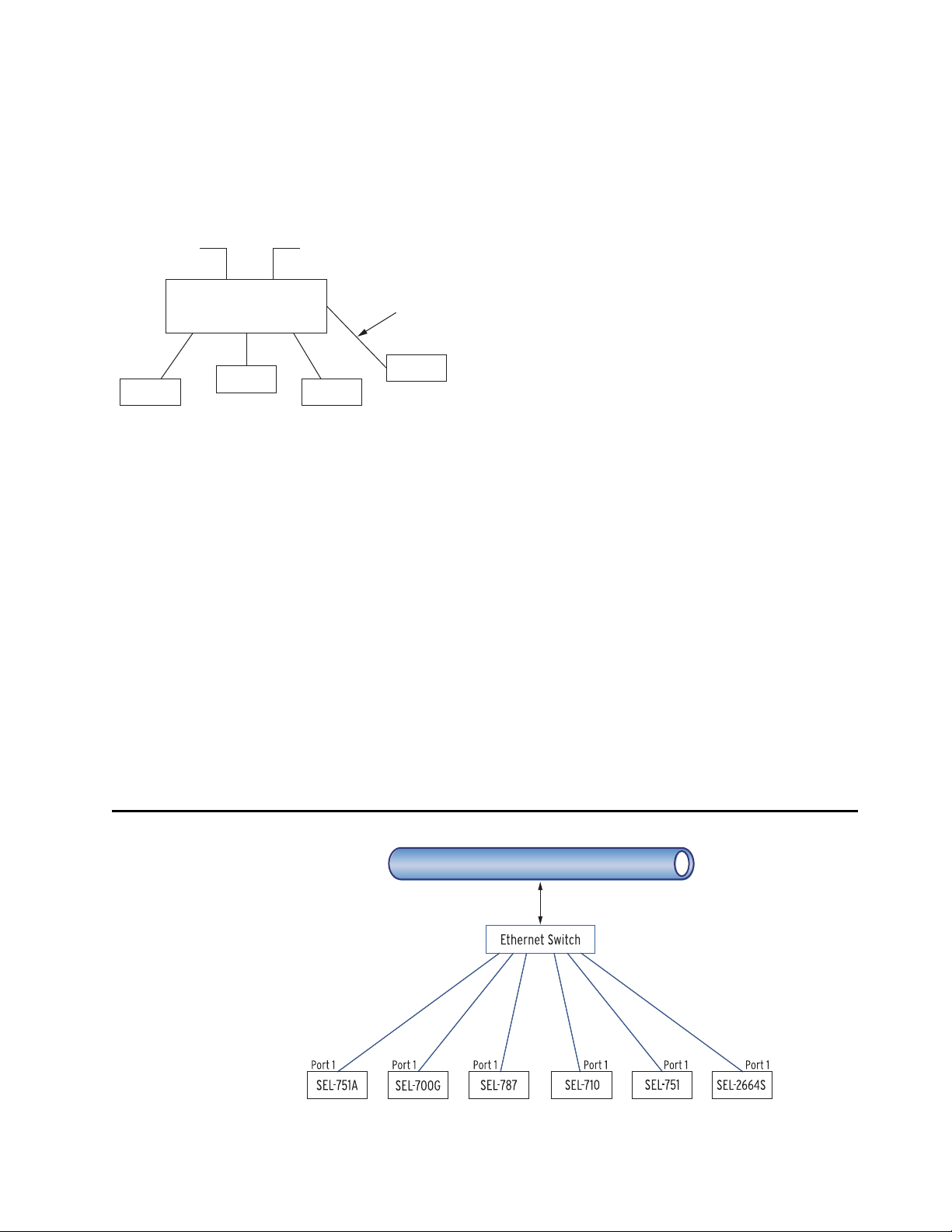
The SEL-2664S has three independently operated serial
ports: one front and one rear EIA-232 serial port and one
rear fiber-optic serial port. Also, the relay supports dual
fiber Ethernet ports in the rear. The relay needs no special
communications software. You can use any system that
emulates a standard terminal system. Establish
communication by connecting computers, modems,
protocol converters, printers, an SEL real-time
automation controller (RTAC), SEL communications
processor, SEL computing platform, SCADA, and/or
RTUs for local or remote communication. Refer to
Table 2 for a list of communications protocols available in
the SEL-2664S.
Neutral Currents (A sec) Magnitude of neutral currents at the injected frequencies in secondary amperes
Stator Insulation (k) Resistance of the stator insulation to ground at the injected frequencies in kilohms, primary
aSecondary and Primary reference the Neutral Grounding Transformer (NGT), not CTN.
bNeutral current (A sec) is shown if CTN_LOC := SEC; otherwise, it is hidden.
Table 1 Metered Quantities (Sheet 2 of 2)
Quantities Description
Table 2 Communications Protocols
Type Description
Simple ASCII Plain language commands for human and simple machine communication.
Use for metering, setting, self-test status, event reporting, and other functions.
Compressed ASCII Comma-delimited ASCII data reports.
Allows external devices to obtain relay data in an appropriate format for direct import into spreadsheets and
database programs. Data are checksum protected.
Fast Meter and Fast
Operate
Binary protocol for machine-to-machine communication.
Quickly updates SEL communications processors, RTUs, and other substation devices with metering informa-
tion, relay elements, I/O status, time tags, and summary event reports. Data are checksum protected. Binary and
ASCII protocols operate simultaneously over the same communications lines, so there is no loss of control, sta-
tus, or metering information while a technician transfers an event report.
Fast SER Protocol Provides SER events to an automated data collection system.
Modbus Serial or Ethernet-based Modbus with point remapping.
Includes access to metering data, protection elements, contact I/O, targets, SER, relay summary event reports,
and settings.
DNP3 Serial or Ethernet-based DNP3 protocols.
Provides default and mappable DNP3 objects that include access to metering data, protection elements, Relay
Word bits, contact I/O, targets, SER, and relay summary event reports.
IEC 61850 Ethernet-based international standard for interoperability among intelligent devices in a substation.
Operates remote bits and I/O. Monitors Relay Word bits and analog quantities.
SNTP Ethernet-based protocol that provides time synchronization of the relay.

Schweitzer Engineering Laboratories, Inc. SEL- 2664S Data Sheet
5
Apply an SEL communications processor as the hub of a
star network, with point-to-point connection between the
hub and the SEL-2664S (see Figure 3).
The communications processor supports external
communications links including the public switched
telephone network for engineering access to dial-out
alerts and private line connections of the SCADA system.
Figure 3 Example Communications System
SEL manufactures a variety of standard cables for
connecting this and other relays to a variety of external
devices. Consult your SEL representative for more
information on cable availability.
SEL-2664S control logic improves integration in the
following ways.
➤Eliminates RTU-to-relay wiring with eight
remote bits. Set, clear, or pulse remote bits through
the use of serial port commands. Program the
remote bits into your control scheme with SELOGIC
control equations. Use remote bits for SCADA-type
control operations, such as trip and close.
➤Replaces traditional latching relays. Replace as
many as eight traditional latching relays for such
functions as “remote control enable” with latch bits.
Program latch set and latch reset conditions with
SELOGIC control equations. Use optoisolated inputs,
remote bits, or any programmable logic condition to set
or reset the nonvolatile latch bits. Each latch bit retains
its state when the relay loses power.
➤Eliminates external timers. Replace external
timers for custom protection or control schemes
with eight general-purpose SELOGIC control equa-
tion timers. Each timer has independent time-delay
pickup and dropout settings. Program each timer
input with any element you need (e.g., time qualify
a current element). Assign the timer output to trip
logic, transfer trip communications, or other control
scheme logic.
Fast SER Protocol
SEL Fast SER Protocol provides SER events to an automated
data collection system. SEL Fast SER Protocol is
available on any serial port. Devices with embedded
processing capability can use these messages to enable
and accept unsolicited binary SER messages from the
SEL-2664S Relay.
SEL relays and communications processors have two
separate data streams that share the same serial port. The
normal serial interface consists of ASCII character
commands and reports that are human readable through
use of a terminal or terminal emulation package. The
binary data streams can interrupt the ASCII data stream to
obtain information, and then allow the ASCII data stream
to continue. This mechanism allows use of a single
communications channel for ASCII communications
(e.g., transmission of a long event report) interleaved with
short bursts of binary data to support fast acquisition of
metering or SER data.
Ethernet Network Architectures
Figure 4 Simple Ethernet Network Configuration
Dial-Up ASCII Link SCADA Link
SEL Communications Processor
ASCII Reports Plus
Interleaved Binary Data
SEL-2664S
IED
IED IED
Cat 5 shielded twisted pair (STP) cables
with RJ45 connectors (SEL-C627/C628)
for copper Ethernet ports
OR
Fiber-optic Ethernet cables with
LC connectors (SEL-C808) for
fiber-optic Ethernet ports
NETWORK
Fiber only

SEL- 2664S Data Sheet Schweitzer Engineering Laboratories, Inc.
6
Figure 5 Simple Ethernet Network Configuration With Dual Redundant Connections (Failover Mode)
Figure 6 Simple Ethernet Network Configuration With Ring Structure (Switched Mode)
Operator Controls
There are multiple methods for accessing the operator
interface of the relay. As shown in Figure 20, the front
and side panels have eight LEDs that indicate the
ENABLED, TRIP, WARNING, 64S, 64F, 59N, 64F MODULE FAIL,
64S INJECT ON status of the relay. The front panel also
provides a TARGET RESET pushbutton for resetting the relay
and the targets.
Relay and Logic Settings Software
QuickSet simplifies settings and provides analysis
support for the SEL-2664S. Create and manage relay
settings with QuickSet in the following ways:
➤Develop settings offline with an intelligent settings
editor that only allows valid settings.
➤Create SELOGIC control equations with a drag-and-
drop text editor.
➤Configure proper settings through the use of online
help.
➤Organize settings with the relay database manager.
➤Load and retrieve settings through use of a simple
PC communications link.
With QuickSet, you can use integrated waveform and
harmonic analysis to verify settings, analyze events, and
analyze power system events.
NETWORK
Cat 5 shielded twisted pair (STP) cables
with RJ45 connectors (SEL-C627/C628)
for copper Ethernet ports
OR
Fiber-optic Ethernet cables with
LC connectors (SEL-C808) for
fiber-optic Ethernet ports
Fiber only
Ethernet Switch (Managed)
NETWORK
Cat 5 shielded twisted pair (STP) cables
with RJ45 connectors (SEL-C627/C628)
for copper Ethernet ports
OR
Fiber-optic Ethernet cables with
LC connectors (SEL-C808) for
fiber-optic Ethernet ports
Fiber only

Schweitzer Engineering Laboratories, Inc. SEL- 2664S Data Sheet
7
The following features of QuickSet monitor, commission,
and test the SEL-2664S.
➤The PC interface remotely retrieves power system
data.
➤The HMI monitors meter data, Relay Word bits,
and output contacts status during testing. The
control window allows resetting of diagnostics, and
targets.
➤The Firmware Loader in the Tools menu helps you
upgrade the firmware.
Applications
The SEL-2664S is intended for high-resistance grounded
generator applications and cannot be used with low-
impedance-grounded, solidly grounded, and ungrounded
configurations. See Application Considerations in the
SEL-2664S Instruction Manual for additional details.
You can use the SEL-2664S to provide protection at
standstill and online with most typical levels of third-
harmonic voltage (VN3). The injection-based function of
the SEL-2664S requires that VN/NN terminal voltage
remains under 26 V peak. If a generator produces VN3
above this level, even under normal load conditions, the
injection signal stops, disabling the 64S elements.
However, 59N1, 59NRMS, and 64F elements continue to
protect the generator, and 64S elements are immediately
restored when VN3 drops below the safe level. Because
high VN3 indicates there is no ground fault near neutral,
the disabling of 64S elements has an insignificant impact
on protection.
If you want to avoid disabling 64S elements, the
SEL-2664S can be configured to inject a signal at an
NGR Tap. See Figure 7 for basic ac connections using the
NGR Tap.
Figure 7 Basic AC Connections Using the NGR Tap
Figure 8 and Figure 9 show the ac connections for the
SEL-2664S with the neutral CT on the secondary side of
the neutral grounding transformer.
Figure 8 AC Connections With Neutral CT on the
Secondary Side of the Neutral Grounding Transformer
IN
TAP %
NGR
NGT
CTN
D02/VN
D01/NN
C02
C01
SEL-2664S
2-C Twisted Pair.
Do not ground the
CTN leads.
I_SRC
100%
X1 X2
IN
NGR
NGT
CTN
D02/VN
D01/NN
C02
C01
SEL-2664S
2-C Twisted Pair.
Do not ground the
CTN leads.
I_SRC
X1 X2

SEL- 2664S Data Sheet Schweitzer Engineering Laboratories, Inc.
8
Figure 9 AC Connections for the SEL-2664S and
SEL-700G Relays With Neutral CTs on the Secondary
Side of the Neutral Grounding Transformer
Figure 10 shows the ac connections for the SEL-2664S
with the neutral ground resistor (NGR) and CTN on the
primary side and a neutral voltage transformer.
Figure 10 AC Connections With Neutral CT on the
Primary Side and Neutral Voltage Transformer
Figure 11 shows the ac connections with NGR in the
secondary side of a wye-broken delta grounding
transformer on the generator terminals.
Figure 11 AC Connections With NGR in the Secondary
Side of a Wye-Broken Delta Grounding Transformer on the
Generator Terminals
Figure 12 shows the typical ac connections for protection
using redundant relays shown with neutral CTs on the
secondary side of the neutral grounding transformer. This
application requires Relay 1 to set the Injection Source
Mode setting, MODE_SRC := P1 and Relay 2 to set the
Injection Source Mode setting, MODE_SRC := P2.
Figure 12 AC Connections for Protection Using
Redundant Relays Shown With Neutral CTs on the
Secondary Side of the Neutral Grounding Transformer
IN
NGR
CTN 1
D02/VN
D01/NN
C02
C01
SEL-2664S
X1 X2
NGT
E11/VN
E12/NN
SEL-700G
2-C Twisted Pair. Do not
ground the CTN leads.
I_SRC
NGR
CTN IN
D02/VN
I_SRC
D01/NN
C02
C01
SEL-2664S
X1
X2
Neutral Voltage
Transformer
2-C Twisted Pair. Do not
ground the CTN leads.
IN
NGR
NGT
CTN
D02/VN
D01/NN
C02
C01
SEL-2664S
X1 X2
2-C Twisted Pair.
Do not ground the
CTN leads.
I_SRC
IN
NGR
CTN 1
D02/VN
D01/NN
C02
C01
SEL-2664S
X1 X2
Relay 1
NGT
CTN 2
X1 X2
IN
D02/VN
D01/NN
C02
C01
SEL-2664S
Relay 2
2-C Twisted Pair. Do
not ground the CTN
leads. I_SRC
I_SRC

Schweitzer Engineering Laboratories, Inc. SEL- 2664S Data Sheet
9
The SEL-2664S is generally applied to single generators
with high-resistance grounded neutral as shown in
Figure 8 through Figure 12. Similarly, it can also be
applied to a parallel generators configuration if only one
of the generators is grounded (e.g., cross-compound
generators).
For two generators connected in parallel, each with high-
resistance grounded neutral but sharing a common step-
up transformer, you can use two SEL-2664S Relays
(see Figure 13), and follow the special considerations and
limitations described in the SEL-2664S Instruction
Manual for such a configuration.
Figure 13 Parallel Generators Configuration—AC Connections Using Two SEL-2664S Relays
See Figure 14 for a typical example of the dc connections
for 100 percent stator ground protection using the
SEL-2664S Stator Ground Protection Relay (stator-to-
ground insulation resistance measurement) and the
SEL-2664 Field Ground Module (dc field-to-ground
insulation resistance measurement).
Figure 14 Typical DC Connections for an SEL-2664S
Application
NGR2
NGT2
CTN2A
VN
NN
X2
Generator 2 Generator 1
X1
CTN2B CTN1B
of
SEL-2664S-2
To
CO1
To
CO2
of
SEL-2664S-2
To
CO1
To
CO2
Generator Relay
(if used)
VN
NN
NGR1
CTN1A
X1 X2
NGT1
IN
D02/VN
D01/NN
C02
C01
SEL-2664S-1
2-C twisted pair (preferably shielded)
Do not ground the CTN leads.
I_SRC
IN
D02/VN
D01/NN
C02
C01
SEL-2664S-2
To
CTN1B
& CTN2B
I_SRC
52G1
52G2
WYE
GSU XFMR
DELTA
Generator Relay
(if used)
A11A10 IN01
AO1 AO2 AO3
Alarm
Self Test/Status
SEL-2664S
43AMP
ON
Fiber-Optic Cable
With ST Connectors
From SEL-2664
RXTX
Port 2
A04
A05
Trip 86G
or
Ground Fault Alarm
+/H
BO1
BO2
–/N
-DC
+DC
OUT02
GND
OUT01

SEL- 2664S Data Sheet Schweitzer Engineering Laboratories, Inc.
10
Relay Mounting and Dimensions
Figure 15 SEL-2664S Wall-Mount Dimensions
Figure 16 SEL-2664S Connection Diagram for Wall-Mount Option

Schweitzer Engineering Laboratories, Inc. SEL- 2664S Data Sheet
11
Figure 17 SEL-2664S Panel-Mount Dimensions
Figure 18 SEL-2664S Connection Diagram for Rack and Panel-Mount Options
Figure 19 SEL-2664S Rack-Mount Dimensions

SEL- 2664S Data Sheet Schweitzer Engineering Laboratories, Inc.
12
Relay Features and Connections
Figure 20 SEL-2664S Front and Side Faceplates
Terminal D: Neutral Voltage
VN/ I_SRC Injection Source
Connections
Port 3:
EIA 232 Serial Port
Terminal C:
Neutral Current
IN Connections
Terminal B :
Power Supply 125/250
Vdc or 110/240 Vac
Port 2:
Fiber-Optic EIA-232
Serial Port
Terminal A:
Two Digital Inputs, Optically Isolated
and Internally Wetted With 24 Vdc
Four Digital Outputs, OUT01-Form C
OUT02, 03, 04-Form A
Port 1:
Dual Fiber-Optic
Ethernet Ports
Front
Side

Schweitzer Engineering Laboratories, Inc. SEL- 2664S Data Sheet
13
Specifications
Compliance
Designed and manufactured under an ISO 9001 certified quality
management system
47 CFR 15B, Class A
This equipment has been tested and found to comply with the limits for a
Class A digital device, pursuant to part 15 of the FCC Rules. These
limits are designed to provide reasonable protection against harmful
interference when the equipment is operated in a commercial
environment. This equipment generates, uses, and can radiate radio
frequency energy and, if not installed and used in accordance with the
instruction manual, may cause harmful interference to radio
communications. Operation of this equipment in a residential area is
likely to cause harmful interference in which case the user will be
required to correct the interference at his own expense.
UL Listed to U.S. and Canadian safety standards (File E212775; NRGU;
NRGU7)
CE Mark
RCM Mark
General
CBCT Current Input (IN)
Nominal Input Current: 5 mA ac rms
Saturation Current Rating: Linear to 20 mA peak
Continuous Thermal Rating: 1 A
Measurement Clipping Level: 22 mA Peak
One-Second Thermal Rating: 10 A
Burden Rating: 10
Rated Insulation Voltage (Ui): Galvanically connected to 64S terminal
common
Neutral Voltage Input (VN)
Rated Operating Voltage (Ue): 2.5–240 Vac
Rated Insulation Voltage (Ui): 300 Vac
Maximum Continuous Overvoltage
Rating: 275 Vac
Injection Source (I_SRC)
Source Rating: 50 VA continuous
Nominal Injected Current
Amplitude: 0.5–5.0 A rms
Continuous Thermal Rating: 5 A rms
Amplifier Clipping Level: >±20 V Peak
Four Frequency Multisine Injection
For 60 Hz nominal:
For 50 Hz nominal:
18, 24, 36, and 48 Hz
15, 20, 30, and 40 Hz
Maximum Open Terminal Voltage: 26 V peak
Protection: Self-protecting
Power Supply
Relay Start-Up Time: Approximately 5–10 seconds (after
power is applied until the ENABLED
LED turns on)
High-Voltage Supply
Rated Supply Voltage: 110–240 Vac, 50/60 Hz
110–250 Vdc
Input Voltage Range: 85–264 Vac
85–300 Vdc
Power Consumption: <120 VA (ac)
<120 W (dc)
Interruptions: 10 ms @ 125 Vdc
10 ms @ 120 Vac
Fuse Ratings
HV Power Supply Fuse
Rating: 1.6 A
Maximum Rated Voltage: 300 Vdc, 277 Vac
Breaking Capacity: 200 A at 250 Vac
Type: Time-lag T
Output Contacts
General
The relay supports Form A and Form C outputs.
Dielectric Test Voltages: 2500 Vac
Impulse Withstand Voltage (UIMP): 5000 V
Mechanical Durability: 100,000 no-load operations
Standard Contacts
Pickup/Dropout Time: 8 ms (coil energization to contact
closure)
Rated Insulation Voltage: 300 Vdc
Make: 30 A @ 250 Vdc per IEEE C37.90
Continuous Carry: 6 A @ 70°C
4 A @ 85°C
Thermal: 50 A for 1 s
Contact Protection: 360 Vdc, 80 J MOV protection across
open contacts
Breaking Capacity (10,000 Operations) per IEC 60255-0-20:1974:
24 Vdc 0.75 A L/R = 40 ms
48 Vdc 0.50 A L/R = 40 ms
125 Vdc 0.30 A L/R = 40 ms
250 Vdc 0.20 A L/R = 40 ms
Cyclic (2.5 Cycles/Second) per IEC 60255-0-20:1974:
24 Vdc 0.75 A L/R = 40 ms
48 Vdc 0.50 A L/R = 40 ms
125 Vdc 0.30 A L/R = 40 ms
250 Vdc 0.20 A L/R = 40 ms
AC Output Ratings
Maximum Operational
Vo l t a g e ( U e) Rating: 240 Vac
Insulation Voltage (Ui) Rating
(excluding EN 61010-1): 300 Vac
Contact Rating Designation: B300
Utilization Category: AC-15
One-Second Thermal: 50 A
Voltage Protection Across Open
Contacts: 270 Vac, 80 J
B300 (5 A Thermal Current, 300 Vac Max)
Maximum Current Max VA
Voltage 120 Vac 240 Vac —
Make 30 A 15 A 3600
Break 3 A 1.5 A 360
PF < 0.35, 50–60 Hz
AC-15
Operational Voltage (Ue) 120 Vac 240 Vac
Operational Current (Ie) 3 A 1.5 A
Make Current 30 A 15 A
Break Current 3 A 1.5 A
Electromagnetic loads > 72 VA, PF < 0.3, 50–60 Hz

SEL- 2664S Data Sheet Schweitzer Engineering Laboratories, Inc.
14
Optoisolated Control Inputs (Internally Wetted to 24 Vdc)
Current Draw at Nominal DC
Voltage: 4 mA typical
Rated Insulation Voltage (Ui): 300 Vac
Rated Impulse Withstand Voltage
(Uimp): 5000 V
Pickup/Dropout Time: <20 ms
Time-Code Input
Format: Demodulated IRIG-B
On (1) State:
Off (0) State:
Vih 2.2 V
Vil 0.8 V
Input Impedance: 2 k
Synchronization Accuracy Internal
Clock:
1 µs
All Reports: 5 ms
Simple Network Time Protocol
(SNTP) Accuracy Internal
Clock:
5 ms
Unsynchronized Clock Drift Relay
Powered: 2 minutes per year, typically
Communications Ports
Standard EIA-232 (2 Ports)
Location: Front Panel
Rear Panel
Data Speed: 300–38400 bps
Ethernet Port
Dual 100BASE-FX (LC connector)
Standard Multimode Fiber-Optic Serial Port
Location: Rear Panel
Data Speed: 300–38400 bps
Fiber-Optic Ports Characteristics
Port 1 (or 1A, 1B) Ethernet
Wavelength: 1300 nm
Optical Connector Type: LC
Fiber Type: Multimode
Link Budget: 16.1 dB
Typical TX Power: –15.7 dBm
RX Min. Sensitivity: –31.8 dBm
Fiber Size: 62.5/125 µm
Approximate Range: ~6.4 km
Data Rate: 100 Mbps
Typical Fiber Attenuation: –2 dB/km
Port 2 Serial
Wavelength: 820 nm
Optical Connector Type: ST
Fiber Type: Multimode
Link Budget: 8 dB
Typical TX Power: –16 dBm
RX Min. Sensitivity: –24 dBm
Fiber Size: 62.5/125 µm
Approximate Range: ~1 km
Data Rate: 5 Mbps
Typical Fiber Attenuation: –4 dB/km
Communications Protocols
SEL, Modbus, DNP3, FTP, TCP/IP, Telnet, SNTP, IEC 61850, MIRRORED
BITS
Operating Temperature
IEC Performance Rating
(per IEC/EN 60068-2-1
and 60068-2-2):
–40° to +85°C (–40° to +185°F)
Not applicable to UL applications
Operating Environment
Insulation Class: 1
Pollution Degree: 2
Overvoltage Category: II
Atmospheric Pressure: 80–110 kPa
Relative Humidity: 5%–95%, noncondensing
Maximum Altitude Without
Derating (Consult Factory for
Higher Altitude Derating): 2000 m
Dimensions
Surface Mounting
Width: 26.12 cm (10.28 in) maximum
Depth: 13.21 cm (5.2 in) maximum
(includes mounting brackets)
Height: 26.54 cm (10.45 in) maximum
(includes mounting brackets)
Panel Mounting
Width: 19.12 cm (7.53 in) maximum
Depth: 26.11 cm (10.28 in) maximum
Height: 23.70 cm (9.33 in) maximum
Rack Mounting
Width: 48.26 cm (19 in) maximum
Depth: 26.11 cm (10.28 in) maximum
Height: 26.59 cm (10.47 in) maximum
Weight
Wall Mount:
Panel Mount:
Rack Mount:
4.02 kg (8.87 lbs)
4.69 kg (10.33 lbs)
7.96 kg (17.55 lbs)
#6 Ground Screw and #6 Chassis Screw Tightening Torque
Minimum:
Maximum:
1.13 Nm (10 in-lb)
1.36 Nm (12 in-lb)
#8 Chassis and Wall Mount Bracket Screw Tightening Torque
Minimum
Maximum:
1.24 Nm (11 in-lb)
1.47 Nm (13 in-lb)
#6 Captive Screw in Front Bezel, Screw Tightening Torque for Panel/
Rack Mount Options
Minimum:
Maximum:
1.13 Nm (10 in-lb)
1.36 Nm (12 in-lb)
1/4-20 Hex Nut Tightening Torque for Panel/ Rack Mount Options
Minimum:
Maximum:
5.08 Nm (45 in-lb)
6.21 Nm (55 in-lb)
Terminal Connections for Terminal Blocks A, B, and C
Compression Plug Tightening Torque
Minimum:
Maximum:
0.5 Nm (4.43 in-lb)
0.6 Nm (5.31 in-lb)
Compression Plug Mounting Ear Screw Tightening Torque
Minimum:
Maximum:
0.2 Nm (1.77 in-lb)
0.3 Nm (2.65 in-lb)

Schweitzer Engineering Laboratories, Inc. SEL- 2664S Data Sheet
15
Terminal Connections for Terminal Block D
Compression Plug Tightening Torque
Minimum:
Maximum:
0.5 Nm (4.43 in-lb)
0.8 Nm (7.08 in-lb)
Compression Plug Mounting Ear Screw Tightening Torque
Minimum:
Maximum:
0.5 Nm (4.43 in-lb)
0.8 Nm (7.08 in-lb)
Wire Sizes
Use 105°C-rated wiring. Wire sizes for grounding (earthing) and power
connections are dictated by the terminal blocks and expected load
currents. Use the following table as a guide in selecting wire sizes.
Refer to SEL Application Note AN2014-08 for wiring and termination
guidance. Strip the wires 8 mm (0.31 in) for termination and
installation.
Product Standards
Measuring Relays and Protection
Equipment:
IEC 60255-26:2013
IEC 60255-27:2013
Type Tests
Environmental Tests
Enclosure Protection: IEC 60529:2001 + CRDG:2003
IP20 for terminals
Vibration Resistance: IEC 60255-21-1:1998
IEC 60255-27:2013; Section 10.6.2.1
Endurance: Class 1 (Class 2 for wall mount only)
Response: Class 2
Shock Resistance: IEC 60255-21-2:1998
IEC 60255-27:2013; Section 10.6.2.2
IEC 60255-27:2013; Section 10.6.2.3
Withstand:
Response:
Bump:
Class 1
Class 2
Class 1
Seismic (Quake Response): IEC 60255-21-3:1993
IEC 60255-27:2013; Section 10.6.2.4
Response: Class 2
Cold: IEC 60068-2-1:2007
IEC 60255-27:2013; Section 10.6.1.2
IEC 60255-27:2013; Section 10.6.1.4
–40°C, 16 hours
Dry Heat: IEC 60068-2-2:2007
IEC 60255-27:2013; Section 10.6.1.1
IEC 60255-27:2013; Section 10.6.1.3
85°C, 16 hours
Damp Heat, Steady State: IEC 60068-2-78:2001
IEC 60255-27:2013; Section 10.6.1.5
40°C, 93% relative humidity, 10 days
Damp Heat, Cyclic: IEC 60068-2-30:2001
IEC 60255-27:2013; Section 10.6.1.6
25–55°C, 6 cycles, 95% relative
humidity
Wire Size
Connection TypeaMinimum Maximum
Grounding (Earthing) 18 AWG (0.8 mm2) 14 AWG (2.1 mm2)
Power 16 AWG (1.3 mm2) 14 AWG (2.1 mm2)
Current (IN) 18 AWG (0.8 mm2) 14 AWG (2.1 mm2)
Potential (Voltage) (VN) 16 AWG (1.3 mm2) 10 AWG (5.26 mm2)
Contact I/O 18 AWG (0.8 mm2) 14 AWG (2.1 mm2)
aFor all connection types, the insulation voltage must be
300 V minimum.
Dielectric Strength and Impulse Tests
Dielectric (HiPot): IEC 60255-27:2013; Section 10.6.4.3
IEEE C37.90-2005
2.5 kVac on contact outputs
3.6 kVdc on power supply IN, VN,
contact input terminals
Impulse: IEC 60255-27:2013; Section 10.6.4.2
Severity Level: 0.5 J, 5 kV
IEEE C37.90:2005
Severity Level: 0.5 J, 5 kV
RFI and Interference Tests
EMC Immunity
Electrostatic Discharge Immunity: IEC 61000-4-2:2008
IEC 60255-26:2013; Section 7.2.3
IEEE C37.90.3:2001
Severity Level 4
8 kV contact discharge
15 kV air discharge
Radiated RF Immunity: IEC 61000-4-3:2010
IEC 60255-26:2013; Section 7.2.4
10 V/m
IEEE C37.90.2-2004
20 V/m
Fast Transient, Burst Immunity*: IEC 61000-4-4:2012
IEC 60255-26:2013; Section 7.2.5
4 kV @ 5.0 kHz
2 kV @ 5.0 kHz for comm. ports
Surge Immunity*: IEC 61000-4-5:2005
IEC 60255-26:2013; Section 7.2.7
1 kV line-to-line
2 kV line-to-earth
Surge Withstand Capability
Immunity*:
IEC 61000-4-18:2010
IEC 60255-26:2013; Section 7.2.6
2.5 kV common mode
1 kV differential mode
1 kV common mode on comm. ports
IEEE C37.90.1-2002
2.5 kV oscillatory
4 kV fast transient
Conducted RF Immunity: IEC 61000-4-6:2008
IEC 60255-26:2013; Section 7.2.8
10 Vrms
Magnetic Field Immunity: IEC 61000-4-8:2009
IEC 60225-26:2013; Section 7.2.10
Severity Level: 1000 A/m for
3 seconds
100 A/m for 1 minute; 50/60 Hz
IEC 61000-4-9:2001
Severity Level: 1000 A/m
IEC 61000-4-10:2001
Severity Level: 100 A/m (100 kHz
and 1 MHz)
Power Supply Immunity: IEC 61000-4-11:2004
IEC 61000-4-17:1999
IEC 61000-4-29:2000
IEC 60255-26:2013; Section 7.2.11
IEC 60255-26:2013; Section 7.2.12
IEC 60255-26:2013; Section 7.2.13
EMC Emissions
Conducted Emissions: IEC 60255-26:2013 Class A
FCC 47 CFR Part 15.107 Class A
ICES-003 Issue 6
EN 55011:2009 + A1:2010 Class A
EN 55022:2010 + AC:2011 Class A
EN 55032:2012 + AC:2013 Class A
CISPR 11:2009 + A1:2010 Class A
CISPR 22:2008 Class A
CISPR 32:2015 Class A

16
© 2014–2019 by Schweitzer Engineering Laboratories, Inc. All rights reserved.
All brand or product names appearing in this document are the trademark or registered
trademark of their respective holders. No SEL trademarks may be used without written
permission. SEL products appearing in this document may be covered by U.S. and Foreign
patents.
Schweitzer Engineering Laboratories, Inc. reserves all rights and benefits afforded under
federal and international copyright and patent laws in its products, including without lim-
itation software, firmware, and documentation.
The information in this document is provided for informational use only and is subject to
change without notice. Schweitzer Engineering Laboratories, Inc. has approved only the
English language document.
This product is covered by the standard SEL 10-year warranty. For warranty details, visit
selinc.com or contact your customer service representative.
*PDS2664S-01*
2350 NE Hopkins Court • Pullman, WA 99163-5603 U.S.A.
Tel: +1.509.332.1890 • Fax: +1.509.332.7990
SEL- 2664S Data Sheet Date Code 20190416
Radiated Emissions: IEC 60255-26:2013 Class A
FCC 47 CFR Part 15.109 Class A
ICES-003 Issue 6
EN 55011:2009 + A1:2010 Class A
EN 55022:2010 + AC:2011 Class A
EN 55032:2012 + AC:2013 Class A
CISPR 11:2009 + A1:2010 Class A
CISPR 22:2008 Class A
CISPR 32:2015 Class A
* Front-port serial cable (non-fiber) lengths assumed to be <3m.
Processing Specifications and Oscillography
AC Voltage and Current Inputs: 32 samples per power system cycle
(based on FNOM)
Digital Filtering: All analog quantities are calculated
every 1/4 cycle over 640 samples.
Protection and Control Processing: Processing interval is 4 times per power
system cycle (except for math
variables and analog quantities, which
are processed every 25 ms).
Oscillography
Length: 180 cycles
Sampling Rate: 32 samples per cycle, unfiltered
Trigger: Programmable with Boolean
expression
Format: Compressed ASCII
Time-Stamp Resolution: 1 ms
Time-Stamp Accuracy: 5 ms
Sequential Events Recorder
Time-Stamp Resolution: 1 ms
Time-Stamp Accuracy (with
respect to time source): 5 ms
Relay Elements
Stator Ground (64S)
Pickup Range: OFF, 0.1 k–10 kprimary*
Pickup/Measurement Accuracy,
Steady State:
10% of pickup ±50 for pickup
2k
±15% pickup for 2 k< pickup
10 k
Time Delay Range: 0.1–400.0 seconds
Time Delay Accuracy: 0.1% of user setting, 4.2 ms at 60 Hz
* Metering for stator insulation resistance to ground is supported as high as
99 k.
Neutral Grounding Resistor (NGR) Monitor
NGR Short Pickup Range: OFF, 0.01 –4000
NGR Open Pickup Range: OFF, 0.1 –4000
Pickup Accuracy: ±10% of user setting plus ±0.01 *
* Accuracy specification applies when no stator insulation fault is present.
Neutral Fundamental Overvoltage (59N)
Pickup Range: OFF, 5.0–150.0 V
Pickup Accuracy: 5% of user setting plus 1 V
Time Delay Range: 0.1–400.0 seconds
Time Delay Accuracy: 0.1% of user setting plus 4.2 ms at
60 Hz
Neutral RMS Overvoltage (59NRMS)
Pickup Range: OFF, 5.0–150.0 V
Pickup Accuracy: 5% of user setting plus 1 V
Time Delay Range: 0.1–400.0 seconds
Time Delay Accuracy: 0.1% of user setting plus 4.2 ms at
60 Hz
Rotor Field Ground Protection (64F)
(Optional—Requires SEL-2664 Field Ground Module)
Pickup Range: OFF, 0.5 k–200 k*
Pickup Accuracy, Steady State: 5% 500 for 48 field voltage
825 Vdc
5% 20 kfor 825 field voltage
1500 Vdc
Pickup Time: 2 s if the injection frequency in the
SEL-2664 is selected at 1 Hz
8 s if the injection frequency in the
SEL-2664 is selected at 0.25 Hz
Time Delay Range: 0.1–400.0 seconds
Time Delay Accuracy: 0.5% 5 ms
* Insulation resistance metering is supported as high as 20 M protection
is supported as high as 200 k.
Metering
Accuracies are specified at 20°C, nominal frequency, unless otherwise
noted.
I_SRC (Injection Source Current)
Magnitude Accuracy: 5% plus 0.05 mA
IN (Neutral Current)
(within 1 mA–16 mA rms): 5% plus 0.05 mA
Stator Ground Insulation
Resistance:
10% of Rf ±50 for Rf 2k
±15% of Rf for 2 k<Rfk
(Rf = stator insulation resistance to
ground)
Rotor Field Insulation Resistance: 5% 500 . for 48 Vdc field
voltage 825 Vdc
5% 20 k. for 825 Vdc field
voltage 1500 Vdc
VN (Neutral Voltage)
(within 2.5–240 V secondary): 5% of user setting plus 1 V
* Typical. Measurement accuracy is affected by installation-specific factors
such as NGR location, parallel generator configuration, injection
transformer heating, accurate knowledge of the NGR tap ratio, etc. The
highest value displayed is 99.99 k. Measurement accuracy improves
at lower insulation resistances.
Table of contents
Other Sel Relay manuals