Selden Furlex Electric Instructions and recipes
597-274-E
2019-04-24
Supplementary manual

2
1. Introduction
Congratulations on the purchase of your new Furlex Electric motor unit. This manual covers installation
and operating instructions for the electric drive unit only.
Installation of the basic furling systems are described in their respective manuals (see below). The model
designation is found on the cover. Part and serial numbers are found on the gearbox, inside the respective
covers.
The Furlex Electric motor unit is compatible with the following manually operated Furlex models:
204S/304S/204TD/304TD (current models)
200S/300S/200TD/300TD (production year 1997-2015)
The electric furling unit is only to be used together with Seldén’s power supply and SEL-Bus system.
We have compiled this manual to help you install and operate your furling system safely and with ease.
Please read the entire manual before assembly and use of the product. Follow the instructions carefully
to avoid damage to the furling system and to avoid the risk of personal injury. Seldén cannot be held
responsible for any problems, damages or personal injuries arising from an improperly installed product.
Keep the manual available for future reference.
User Manual Revision history:
597-274 Revision 0.0 2017-11-06, Revision 1.0 2019-03-20
The latest version of this manual can be downloaded from www.seldenmast.com
Other Seldén documents referred to in this manual are:
595-104 Furlex 200/300S
597-132 Furlex 204/304S
595-231 Furlex 200/300TD
597-418 Furlex 204TD/304TD
597-275 Power supply & SEL-Bus system
Safety Precautions
Carefully pay attention to, and follow the instructions with the following symbols:
ATTENTION
This symbol indicates a critical moment in the assembly or technical advice.
WARNING
This symbol indicates a potentially hazardous situation. If not avoided, this could result
in serious personal injury or damage to property.

Safety notes regarding the electrical installation for the Furlex Electric:
-The installation should be done by a person with marine installations skills. You can nd your local
authorized Furlex dealer at www.seldenmast.com
-Furlex electric is intended only for sail furling purposes together with Seldén furling proles, controlled
by Seldén’s 42V motor drive system.
-Make sure the system is switched o before performing any installation or service.
-Never modify the electric system of your Furlex or its installation drawings - installation, alterations and
maintenance should be performed by a competent marine electrical technician.
-Never alter or modify the rated current amperage of overcurrent protective devices.
-Never leave the craft unattended with the Furlex Electric energized.
Choosing the correct version of Furlex Electric for your boat:
The key to a safe and properly working installation is correct dimensioning in relation to the boat size the
products shall be used on. Seldén provides dimensioning guidelines in catalogues, leaets and on the
website. If there are any questions about selecting the right product, please consult an authorized Seldén
dealer. All dealers are listed at www.seldenmast.com and divided in categories describing their competence.
For Furlex Electric we recommend authorized Furlex dealers or dealers in the category “Advanced Technical
Installations”.
3

Contents
1 Introduction ......................................................................................................................... 2
Contents ................................................................................................................................... 4
2 Furlex Electric................................ ..................................................................................... 5
2.1 Basic Packs for Furlex Electric complete kit ........................................................... 6
2.2 Furlex Electric Retrot pack..... ................................................................................. 8
2.3 Control Pack .............................................................................................................. 10
2.4 Optional parts ............................................................................................................ 11
2.5 Technical specication ............................................................................................. 12
3 Motor Unit installation ........................................................................................................ 14
3.1 Installation preparations Furlex Electric (above deck) .......................................... 14
3.2 Installation preparation for Furlex TD Electric (Through deck) ............................ 15
3.3 Installation of the furling system excluding the electric motor unit .................... 15
3.4 Step by step assembly 204E/304E ......................................................................... 16
3.5 Step by step assembly 204TDE/ 304TDE ............................................................... 18
3.6 Step by step assembly 200S/300S Retrot .......................................................... 21
3.7 Step by step assembly 200TD/300TD Retrot ..................................................... 23
3.8 Step by step assembly 204S/304S Retrot .......................................................... 27
3.9 Step by step assembly 204TD/304TD Retrot ....................................................... 32
4 Electrical Installation .......................................................................................................... 38
4.1 Installation of deck gland and connection box. .................................................... 38
4.2 Connection to Seldén Power supply and SEL-Bus system ................................. 41
5 Operation ............................................................................................................................. 42
5.1 Normal operation ...................................................................................................... 42
5.2 Unfurling ..................................................................................................................... 42
5.3 Furling ......................................................................................................................... 42
5.4 Reducing sail area .................................................................................................... 43
5.5 Emergency furling ..................................................................................................... 44
6 Trouble shooting ................................................................................................................. 45
7 Service and maintenance .................................................................................................. 46
7.1 Frequent maintenance .............................................................................................. 46
7.2 Yearly Inspection points and maintenance............................................................. 46
7.3 Every 5th year ............................................................................................................ 46
8 Technical information ......................................................................................................... 48
4

5
2 Furlex Electric
Furlex Electric is available as a complete kit for both on-deck and through-deck installation.
The electric system is also available as an upgrade of an existing Furlex by replacing the furling line,
drum and line guard assembly with the Furlex Electric Motor unit and related parts in the Furlex
Electric Retrot pack.
Low power consumption
High eciency throughout the electric power and control system. A “sleep mode” is activated to
save power when not in operation.
Powerful enough, but with precise torque limitation.
The electric motor has a computerised controller that monitors the current draw precisely. As soon
as it reaches a pre-set level it cuts out quickly enough to avoid damage to components. The torque
level is programmed into a memory chip so that each size of Furlex Electric has the correct setting.
Resistant to the marine environment
Furlex Electric has an outer cover made of an impact- and UV- resistant composite polymer.
The worm gear is enclosed in a corrosion resistant aluminum housing. The electric motor has its
own housing which is completely sealed and individually pressure tested before delivery.
Two speed operation
A double control button makes it possible to operate the
furler with great precision in the low speed mode.
By pushing both buttons at the same time, high
speed is activated.
Locks in both directions
The worm gear is self-locking (40:1) in both directions,
which means that the sail can be furled from either
the starboard, or the port side of the boat.
Emergency operation
The worm gear has a ½” socket that can be reached
from the starboard side. Seldén’s emergency line
driver is included in the delivery kit.
Compact size -minimised weight and dimensions.
The electric motor is compact, still giving enough power.
This is made possible by raising the voltage up to 42V.
Keeping weight and the dimensions in focus during the
design has resulted in a small unit.

6
Furlex 204E Furlex 304E
Included parts Qty 549-200-20 549-300-20
Halyard Swivel 1549-229-01 549-329-01
Lower Swivel 1549-200-21 549-300-21
Motor Unit 1 549-601-09 549-601-07
Protect. Hose Ø30 mm 1 319-837 319-837
Clip 2312-213 312-213
Emergency Line drive 1539-664-01 539-664-01
Top bearing assembly 1549-226-01 549-326-01
Bearing plug forward 1549-219 549-319
Bearing plug aft 1 549-220 549-320
Sailfeeder assembly 1549-223-01 549-323-01
Deck gland kit 1539-653-01 539-653-01
Locking adhesive 1312-305 312-305
Halyard U-lead kit 1508 -159-02 508-128-02
Prefeeder Pack 1 505-538-01 505-538-01
Lubricating grease 1312-501 312-501
Torx bit set 1 592-087 592-087
2.1 Basic Packs for Furlex Electric complete kit
When Furlex Electric is bought as a complete kit, following Furlex Electric Basic Packs are included
instead of the respective Basic Pack for manual drive. The tables below show the included parts in
each Furlex Electric Basic Pack.
Furlex Electric Basic pack: Standard

7
Furlex 204TDE ø6/7 Furlex 204TDE ø8 Furlex 304TDE
Included parts Qty 549-270-18 549-270-19 549-370-12
Halyard swivel 1549-229-01 549-329-01
Lower swivel 1549-270-11 549-270-13 549-370-13
Motor Unit 1 549- 601-16 549-601-17
Torque tube assembly 1549-272-02 549-372-02
Deck tting assembly 1549-257- 01 549-357- 01
Torque stay with bracket 1 508- 657-02 508 -657- 02
Screw 2153-006 153-062
Halyard U-lead kit 1508 -159-02 508-128-02
Preefeder pack 1505-538-01 505-538-01
Torx bit set 1 592-087 592-087
Top bearing assy 1 549-226-01 549-326-01
Low bearing assembly 1549-238-01 549-338-01
Spring pin 1166-549 166-552
Sail feeder assembly 1549-223-01 549-323-01
Locking adhesive 1312-305 312-305
Template, Deck Collar 1597-425-E 597- 426 -E
Furlex Electric Basic pack: Through Deck

8
2.2 Furlex Electric Retrofit pack
When upgrading an existing Furlex to electric drive, the retrot pack is bought as an extension of the already
existing Furlex system. The tables below show the included parts in the retrot installation kits for each
manually driven Furlex Electric model, respectively.
204S Electric Retrot 304S Electric Retrot
Forestay
dimension, mm Ø6 Ø7 Ø8 Ø8 Ø10
Item Qty 549-601-250 549-601-255 549-601-260 549-601-265 549-601-270
Motor Unit 1 549-601-09 549-601-07
Hub 1549-650 549-609
Washer 1164-540 164-543
Retain. Ring 1301-563 301-554
Ball 5539-034 539-128
Bearing roller 5319-935 319-930
Protective hose 1319-836 319-836
Deck gland kit 1539-653-01 539-653-01
Clip 2312-211 312-211
Toggle 1539-680-01 539-681-01 539-682-01 539-682-01 539-683-01
Emergency
line driver
1539-664-01 539-664-01
Furlex Electric Retrot pack for Furlex 204S/304S (current models)
Furlex Electric Retrot pack for Furlex 200S/300S (1997-2014)
200S Electric Retrot 300S Electric Retrot
Forestay
dimension, mm Ø6 Ø7 Ø8 Ø8 Ø10
Item Qty 549-601-200 549-601-205 549-601-210 549-601-215 549-601-220
Motor Unit 1 549- 601-10 549-601-08
Carrier 2549-653 549-631
Protective hose 1319-836 319-836
Deck gland kit 1539-653-01 539-653-01
Clip 2312-211 312-211
Toggle 1539-680-01 539-681-01 539-682-01 539-682-01 539-683-01
Emergency
line driver
1539-664-01 539-664-01

9
Furlex Electric Retrot pack for Furlex 200TD/300TD (1997-2017) and 204TD/304TD
(current model)
200TD Electric
Retrot
300TD Electric
Retrot
204TD Electric
Retrot
304TD Electric
Retrot
Item Qty 549-601-225 549-601-240 549-601-275 549-601-290
Motor Unit 1 5 49 - 6 01-11 549-601-12 549-601-16 549- 601-17
Carrier 2549-653 549-631 - -
Hub 1 - - 549-650 549-609
Screw MC6S 8x16 mm 2 153-006 -153-006 -
Screw MC6S 10x16 mm 2 - 15 3 - 011 -15 3 - 011
Torque stay with bracket 1 508- 657-02 508- 657-02 508 -657- 02 508-657-02
Protective hose 1319-836 319-836 319-836 319-836
Clip 1312-211 312-211 312-211 312-211
Emergency linedriver 1539-664-01 539-664-01 539-664-01 539-664-01
Lubricating grease 1312-501 312-501 312-501 312-501
Locking adhesive 1312-305 312-305 312-305 312-305

10
Furlex Electric 200/204 Furlex Electric 300/304
Genoa Cutter Genoa Cutter
Included parts Qty 532-815-90 532-815-91 532-815-92 532-815-93
Motor Control Unit
1532-815-20 532-815-21
Connection Box
1532- 487- 01 532- 487- 01
Control Buttons GENOA
1540-459-16 540-459-16
Control Buttons CUTTER
1
540-459-19 540-459-19
Connection cable Orange 3m 531-045 531-045
Connection cable Grey 3m 531-046 531-046
Connection cable Brown 3m 531-047 531-047
2.3 Control Pack
The Control Pack includes the parts that connect the Furlex motor unit to the Seldén Power Supply
and SEL-Bus system. The included parts are presented in the table below:
11
Item Art. No.
Furlex 204E
Furlex 304E
Furlex
204TDE/304TDE
Furlex 200E
Furlex 300E
Furlex 200TDE
Furlex 300TDE
Forestay wire 6-7 mm, eye/
fork extension link, L=90 mm
517-115 - 01 x x
Forestay wire 8-10 mm, Eye/
fork extension link, L=130 mm
517-116 - 01 x x
Shims for toggle, forestay
ø 6-8 mm
164-516 x x
Shims for toggle, forestay
ø 10 mm
164-519 x x
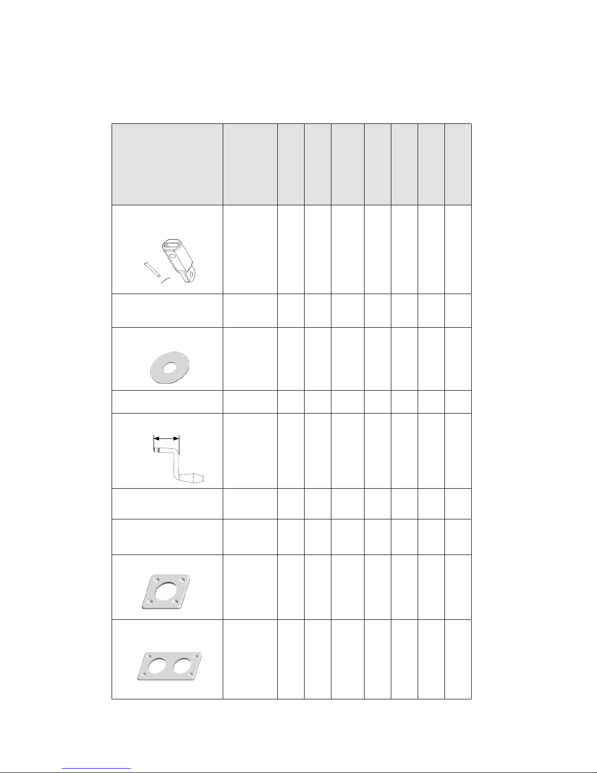
Short crank, emergency,
L=100 mm
533-922 x x x x x x x
Long crank, emergency,
L=32 5 mm
533-923 x x x x x x x
SEL-Bus Converter (for
custom control buttons)
532-827-01 x x x x x x x
Panel, 1 push button 540-461-01 x x x x x x x
Panel, 2 push buttons 540-462-01 x x x x x x x
2.4 Optional parts
Parts that adapt your installation to your individual boat.
L
12
2.5 Technical specification
Electrical specication
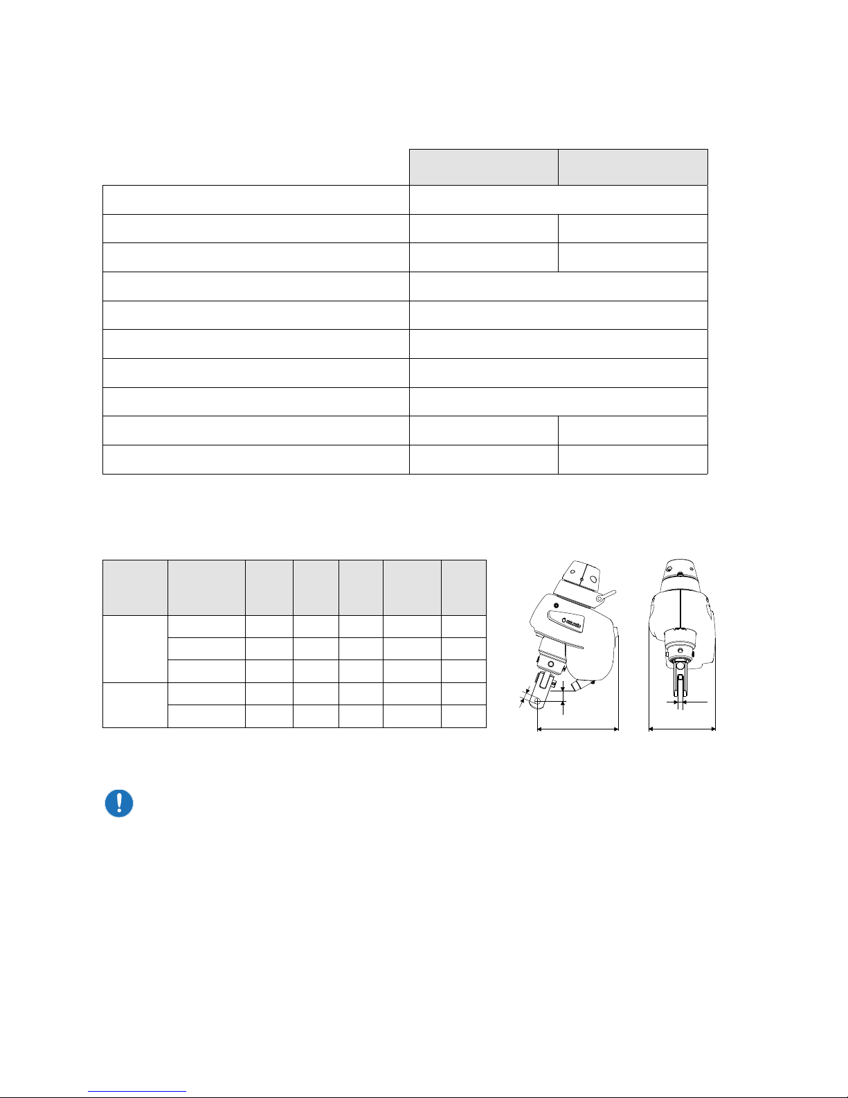
Extension links are available if necessary to provide clearance below the unit, as listed in
chapter ”2.4 Optional parts”.
Furlex Electric 200/204 Furlex Electric 300/304
Input Voltage to motor control unit 42V
Peak Torque 60Nm 90Nm
Peak Current Consumption [42V] 18A 26A
Total Gear Ratio 122:1
Low Speed (unloaded) 30 rpm
High Speed (unloaded) 50 rpm
Efciency (Motor Control Unit + Drive Unit) 30%
Cable Size Motor Control Unit - Motor 6 mm2
Weight, Motor Unit approx 7 kg approx 7 kg
Weight, Motor Control Unit approx 1 kg approx 1 kg
Type Forestay
diameter LHW W2 D2 H2
mm mm mm mm mm mm
204E Ø 6 180 175 12 Ø 10,5 -16
Ø 7 180 175 14 Ø 12,5 -16
Ø 8 183 175 14 Ø 14,5 -7
304E Ø 8 192 175 14 Ø 14,5 23
Ø 10 191 175 16 Ø 16,5 21,5 L
HW
W2
H2
D2
L
HW
W2
H2
D2
Main dimensions, above deck installation:
13
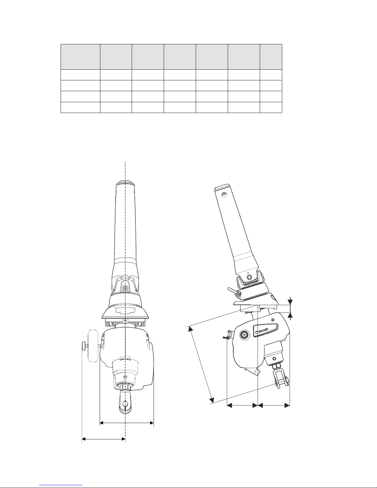
Type A F L1 L2 HW HW1
mm mm mm mm mm mm
200TD 290-450 20 115 114 175 170
204TD 250- 415 20 115 114 175 170
300TD 330-490 18 116 113 175 170
304TD 300-500 30 110 120 175 170
Main dimensions, below deck installation:
F
L2L1
A
HW
HW1

14
3 Motor Unit installation
3.1 Installation preparations Furlex Electric (above deck)
Space requirements
Please check so that there is enough space for the installation. The dimensions are given in the
section ”2.5 Technical Specication”.
Consider space for an anchor. Extension links are available if more space is needed below the
furler, listed in section ”2.4 Optional parts”.
Strength of the forestay attachment
Furlex Electric above deck uses a reinforced toggle capable of handling the torque load.
The forestay attachment needs to have sucient strength to handle the torque loads, with
dimensions according to the table below:
Forestay Dimension, mm
Toggle Ø6 Ø7 Ø8 Ø10
Art No 539-680-01 539-681-01 539-682-01 539-683-01
Length (H) 45 45 55 55
Ø Clevis pin (D1) 12 12 14 16
Fork Width (W1) 10,7 10,7 14,2 14,2
Ø Clevis pin (D2) 10 12 14 16
Fork Width (W2) 12 14 14 16
Forestay Dimension, mm
Extension link Ø6 Ø7 Ø8 Ø10
Art No 517-115 - 01 517-115 - 01 517-116 - 01 517-116 - 01
Length (H) 90 90 130 130
Ø Clevis pin (D1) 12 12 16 16
Fork Width (W1) 10,2 10,2 13,7 13,7
Eye (D2) 12,5 12,5 16,5 16,5
Thickness (W2) 10 10 13,5 13,5
H
W2
W1
D2
D1
W3
D1
W1
HW2
D2

15
3.2 Installation preparation for Furlex TD Electric (Through deck)
Space requirements
Please check so that there is enough space for the installation. The dimensions are given in the
section “2.5 Technical Specication”.
Make sure that there is space for the emergency line driver.
Torque bracket installation
When reefed or under full sail, the furling prole is exposed to a twisting load from the sail.
The forestay attachment of the Furlex TDE is not designed to handle this torque load.
For this reason, the Furlex TDE has a bracket at the rear part of the housing. A torque stay shall
be tted from this bracket to the side of the hull.
Without the torque stay the forestay tting may break, possibly resulting in rig failure.
3.3 Installation of the furling system excluding the electric
motor unit
For complete or retrot installation on Furlex 204/304 systems, please see:
Above deck installation: User manual 597-132 “Furlex 204S&304S”
Below deck installation: User manual 597-418 “Furlex 204TD/304TD”
For retrot installation on Furlex 200/300 systems, please see:
Above deck installation: User manual 595-104 “Furlex 200S&300S”
Below deck installation: User manual 595-231 “Furlex 200TD&300TD”

16
3.4 Step by step assembly 204E/304E
Prior to installation, follow steps in chapter 1.4-3.5 in manual 597-132. Note
that more references are made to this manual during the assembly. Protect
the drum unit and motor unit by working on a clean and soft surface. 597-132-E
1.
Slide the swivel over the terminal. Fit the
adaptor halves and connect the lu extrusion
according to point 4-5 in chapter 3.5, manual
597-132.
2.
Remove the clevis pin and split pin from
the motor unit and t the motor unit over
the hub so that the bronze gear engages
with the carriers in the hub.
3.
Note that the motor unit can be turned 90°
depending on the direction of the forestay
tting in the boat.
Align the holes in the terminal, shaft and
holder.
Fit the clevis pin and split pin.

17
4.
Fit the toggle and, if required, the optional
extension link.
5.
Attach the Furlex Electric system to the
boat by following the steps in chapter 4.3
(stepped mast) or 4.4 (un-stepped mast),
manual 597-132.
Use only Furlex Electric torque toggle
and optional extension link.
18
3.5 Step by step assembly 204TDE/304TDE
Prior to installation, follow steps in chapter 1.4-3.2 and chapter 4 in manual
597-418. Note that more references are made to this manual during the assembly.
Protect the drum unit and motor unit by working on a clean and soft surface. 597-418-E
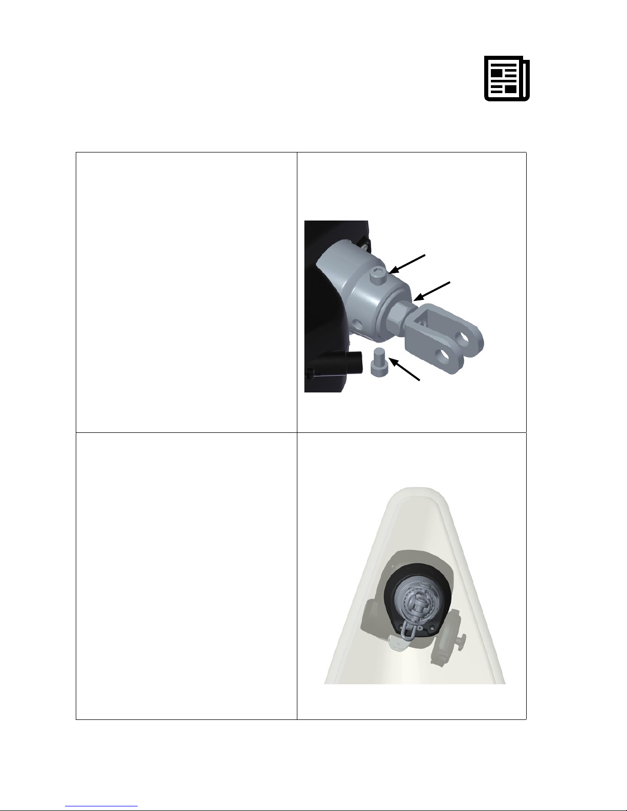
1.
Check that motor unit ts over hub.
Check that the two locking screws (F) t.
Note that motor unit can be turned 90°
depending on the direction of the forestay
tting in the boat. Verifying what holes are
to be used at this point will help facilitate
assembly in the boat.
Finer adjustment can be made by loosening
the locking nut (N) of the fork terminal and
turning the fork. This adjustment also aects
the distance between deck and forestay
attachment - see point 2.
Remove screws and motor unit.
2.
Fit the swivel in the boat without the motor
unit to control following points:
a) Distance between forestay tting and
deck. The distance between tack ring and
deck tting should be approx. 5mm at the
front when the eye of tack-ring is pulled
upwards. If the distance needs to be
adjusted, follow the instructions in chapter
3.2, manual 597-418
b) The position of the motor unit relative to
the fork, which determines the position of
the motor unit in the boat.
Example: if the motor unit is turned
towards portside, access to the emergency
socket will improve.
F
F
N

19
3.
Fit the swivel through the deck tting and
motor unit.
Check that the emergency line driver can be
tted.
Fit the two locking screws (F).
Use locking adhesive.
4.
Fit clevis pin and split pin.
F

20
5.
Determine the position of the torque bracket.
Bracket should be perpendicular to the drive
unit and tted to the port side.
Clean and key the surface. Bond the
torque-bracket to the hull. Use a structural
adhesive.
After curing, assemble the torque stay to the
bracket in the hull.
Turn the drive unit side to side to nd the
neutral position.
Mark the torque stay at (A)
Remove stay and drill ø6.5mm hole for the
clevis pin
Cut-o excess length of the torque stay
leaving => 10mm material to the ø6.5mm
hole.
Round any sharp edges and assemble the
torque stay.
6.
Attach the Furlex Electric system to the
boat by following the steps 6-9 in chapter
5.1 “Rigging”, manual 597-418.
A
New generation 204TDE/304TDE has
no torque handling capacity and a
torque stay is therefore essential for
these models.
Maximum working load on
torque bracket:
Furlex 204TDE: 2100N
Furlex 304TDE: 3600N
Table of contents


