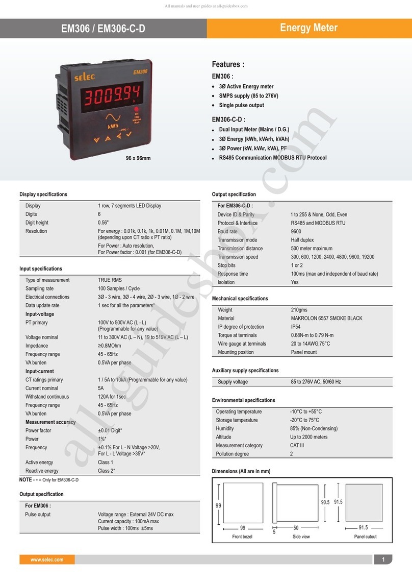
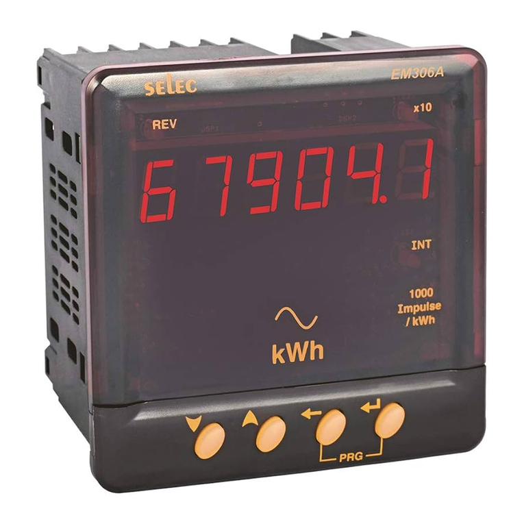
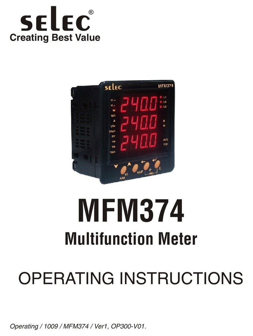
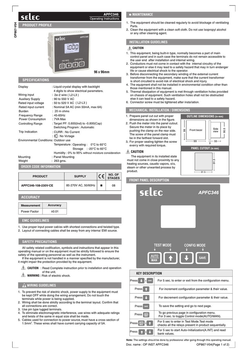
Selec PIC352 User manual

Process Indicator
Selec Controls Pvt. Ltd., India
Tel.: +91-22-4141 846 / 452, Fax: +91-22-41418 408
Website: www.selec.com
Email: [email protected]
PIC352
OPERATING INSTRUCTIONS
Doc. name: OP INST PIC352 OP3023-V01

CONTENTS
Page no.
8. Level 5-lockout module 20
E) CALIBRATION CERTIFICATE 21
7. Level 4-Communication module 19
6. Level 3-Analog o/p & special function module.... 17
5. Level 2-Alarm module (Alarm 2) 15
2. Terminal connections 8
A) OVERVIEW.
1. Features 1
2. Ordering information 2
3. Level 0-Input parameters 13
2. Key's description 12
B) SPECIFICATIONS 3
1. Function menu 11
D) PROGRAMMING.
1. Safety Information 6
4. Level 1 Alarm Module (Alarm 1) 14
C) INSTALLATION.
3. Sensor input wiring 9
4. Output wiring 9

www.selec.com
1
OVERVIEW
96x96mm
SALIENT FEATURES
vOutputs:
0 to 20mA, 4 to 20mA, 0 to 10V & 0 to 5V for Retransmission & Manual output
vUniversal I/O:
Inclusion of all possible inputs and outputs in a single product with high precision sensing & low temperature
drift
vSpecial Features:
vCustomized Upper 4 Digit Alpha-Numeric Display:
User can edit each digit as per requirements
ŸProgrammable backlight as per Alarm
Ÿ24V, 100mA sensor supply for transmitter modules
Ÿ2 SPDT Relays for Alarm Actuation
ŸSingle key Auto / Manual switching
vSensor break indication
vDigital filtering
v90 to 270 VAC/DC supply
vDual 4 digit display
Others
vSensor error compensation
vProgrammable parameter lockouts
vIP65 front panel protection
vRS485 MODBUS communication
Optional Features
vCompliance -

OVERVIEW
2. ORDERING CODE
PIC352-11-U-C-1
1) Universal Input
2) 2 Number of SPDT Relays
3) Analog Output Current & Voltage
4) RS485 Slave Communication
PIC352-11-U-X-1
1 85-270 VAC/DC
2 12-24 VAC/DC
C RS485 Slave Communication
0 No RS485 Slave Communication
0 LED
1 LCD
0 Standard
1 Precision I/O
PIC352-11-U-0-1
1) Universal Input
3) Analog Output Current & Voltage
2) 2 Number of SPDT Relays
1. TECHNICAL SPECIFICATIONS
1. DISPLAY
Display
PIC352 - 96X96- 4 digit Alphanumeric and 4 digit 7-Seg LCD with Selectable Multicolor Backlight as per user
requirements.
Led Status Annunciators OUT1, OUT2, MAN (Manual)
www.selec.com
2

SPECIFICATION
www.selec.com
3
Input
Thermocouple : J, K, T, R, S, C, E, B, N, L, U, W, Platinel II.
RTD : PT100, PT1000
Signal inputs : -5 to 90mV,0 to 10VDC,0 to 20mA DC
(Programmable scale type)
Sampling time 60 ms.
Resolution 1 / 0.1° for TC / RTD.
1 / 0.1 / 0.01 / 0.001 for Analog input. (Decimal point position)
Indication accuracy
Current : 0.1% at 25°C
TC Input : 0.1% of span at 25°C
R&S Input : 0.25% of span at 25°C
RTD Input : 0.1% at 25°C
Voltage : 0.1% at 25°C
Digital filtering OFF, 1 to 99 sec.
Relay contact output Relay 1, Relay 2 : 10A@250VAC or 28VDC
Life expectancy : 50000 cycles at maximum load rating
2. INPUT
3. ALARM OUTPUT
3.1. RETRANSMISSION OUTPUT
Resolution 2uV approx for AOV and 2uA approx for A01
Current output
Range : 0 / 4-20mA
Action : Retransmission
Update rate : 100ms,Maximum output load resistance : 500E
Voltage output
Range : 0-5 / 10V
Action : Retransmission
Update rate : 100msec
Minimum output load resistance : 10k
1. TECHNICAL SPECIFICATIONS
1. DISPLAY
Display
PIC352 - 96X96- 4 digit Alphanumeric and 4 digit 7-Seg LCD with Selectable Multicolor Backlight as per user
requirements.
Led Status Annunciators OUT1, OUT2, MAN (Manual)

SPECIFICATION
www.selec.com
4
Interface standard RS485
Communication address 1 .... 99, maximum of 32 units per line
Transmission mode Half duplex
Transmission protocol MODBUS RTU
Transmission distance 500m maximum
Transmission speed 115200,57600,38400,19200,9600,4800,2400 bits/sec.
Parity None, Odd, Even
Stop bits 1 or 2
Response time 100ms (max and independent of baud rate)
5. SERIAL COMMUNICATION
Operating range
Storage range
Storage humidity
0.....55°C
-20.....75°C
85% max. RH (non condensing) from 0 to 50°C
6. ENVIRONMENTAL CONDITIONS
Power supply 90.....270VAC / DC
Frequency 50 / 60Hz
Power consumption 8VA max
7. POWER SUPPLY
Auto / Manual Concept
User can switch from manual analog 0/P to retransmission mode
by pressing A/M key for 5sec. when in online mode.
NOTE : User must feed the manual output % in HAND level 3
4. FUNCTION
Alarms
Modes : Alarm high, Alarm Low, Band, Serr
Hystersis : Programmable
Annunciator : Programmable
Reset Action : Programmable-Automatic or latched
Standby(Hold) : Programmable-Enable or disable
Pdly : Power ON delay
Rdly : Restart time delay

SPECIFICATION
www.selec.com
8
Sensor type Range
J -200 to 750°C E -200 to 750°C
K -200 to 1350°C B +149 to 1820°C
T -200 to 400°C N -200 to 1300°C
R 0 to 1750°C L -200 to 600°C
S 0 to 1750°C U -200 to 900°C
C 0 to 2300°C W 0 to 2300°C
Platinel II 0 to 1390°C PT100 -200 to 850°C
PT1000 -200 to 850°C
Signal inputs:
WEIGHT : PIC352-11-U-X-1 : 200gms
10. HOUSING : Flame retardant engineering plastic
11. INPUT SENSOR RANGES (for 1°C resolution)
Sensor type Range
Input type Range
Linear mV -5 to 90mV
Voltage 0 to 10VDC
Current 0 to 20mA
Compliance CE
LVD As per BS EN 61010
EMC As per BS EN 61326
Panel sealing IP65
9. SAFETY AND EMC STANDARDS
AC line w.r.t. all inputs and outputs 2500Volts
All other inputs and outputs w.r.t. Relay contacts 2500VAC
8. ISOLATION BREAKDOWN RATINGS

INSTALLATION
SAFETY SUMMARY
This manual is meant for the personnel involved in wiring, installation, operation, and routine
maintenance of the equipment. All safety related codifications; symbols and instructions that appear in this operating
manual or on the equipment must be strictly followed to ensure the safety of the operating personnel as well as the
instrument. If the equipment is not handled in a manner specified by the manufacturer it might impair the protection
provided by the equipment.
CAUTION : Read complete instructions prior to installation and operation of the unit.
CAUTION : Risk of electric shock.
1. SAFETY INFORMATION
INSTALLATION INSTRUCTION
CAUTION :
3. Circuit breaker or mains switch must be installed between power source and supply terminals to facilitate
power 'ON' or 'OFF' function. However this switch or breaker must be installed in a convenient position
normally accessible to an A operator.
2. Conductors must not come in contact with the internal circuitry of the equipment or else it may lead to a
safety hazard that may in turn endanger life or cause electrical shock to the operator.
1. This equipment, being built-in-type,normally becomes a part of the main control panel and in such case
the terminals do not remain accessible to the end user after installation and internal wiring.
MAINTENANCE
1. The equipment should be cleaned regularly to avoid blockage of ventilating parts.
2. Use soft cloth for cleaning. Do not use isopropyl alcohol or any other organic cleaning agent.
4. Thermal dissipation of equipment is met through ventilation holes provided on chassis of equipment. Such
ventilation holes shall not be obstructed else it can lead to a safety hazard.
5. The output terminals shall be strictly loaded to the manufacturer specified values/range.
1. The equipment shall not be installed in environmental conditions other than those specified in this manual.
2. Fuse Protection - The equipment does not contain built-in fuse. Installation of external fuse for electrical
circuitry is highly recommended. Recommended rating of such fuse shall be 275VAC/1 Amp.
3. Since this is a built-in type equipment (finds place in main control panel), its output terminals get connected
to host equipment. Such equipment shall also comply with basic EMI/EMC and safety requirements like BS
EN 61326-1 and BS EN 61010 respectively.
CAUTION :
www.selec.com
6

INSTALLATION
WIRING INSTRUCTION
1. To prevent the risk of electric shock power supply to the equipment must be kept OFF while doing the
wiring arrangement.
2. Terminals and electrically charged parts must not be touched when the power is ON.
3. Wiring shall be done strictly according to the terminal layout with shortest connections. Confirm that all
connections are correct.
4. Use lugged terminals to meet M3.5 screws.
5. To eliminate electromagnetic interference use of short wire with adequate ratings and twists of the
same in equal size shall be made.
6. Cable used for connection to power source, must have a cross section of 1 or greater. These wires
shall have insulation capacity made of at least 1.5KV.
CAUTION :
2. Remove the clamp from the controller.
3. Push the controller into the panel cutout. Secure the controller in its place by pushing the clamp
from the rear side.
The equipment in its installed state must not come in close proximity to any heating sources, caustic
vapors, oils, steam, or other unwanted process by-products.
ELECTRICAL PRECAUTIONS DURING USE
Electrical noise generated by switching of inductive loads can create momentary disruption, erratic display,
latch up, data loss or permanent damage to the instrument.
To reduce noise :
A) Use of MOV across supply of temperature controller & snubber circuits across loads are recommended.
Part number are as follows :
1. Snubber : APRC-01
B) Use separate shielded wires for inputs.
C) The unit should preferably be shielded from the contactor
INSTALLATION GUIDELINES
Mechanical Installation :
For installing the controller
1. Prepare the panel cutout with proper dimensions as shown.
OVERALL DIMENSIONS (All dimensions in mm)
Panel Cutout
99
99 45.5
64
4
10
55 90.5
90.5
CAUTION :
www.selec.com
7

INSTALLATION
PIC352-11-U-C-1
1. Use proper input power cables with shortest connections and twisted type.
2. Layout of connecting cables shall be away from any internal EMI source.
EMC Guidelines :
2. TERMINAL CONNECTIONS
Digital input
Sensor supply
NPN / PNP
24VDC, 80mA Analog input
PIC352-11-U-0-1
www.selec.com
8

www.selec.com
9
INSTALLATION
3. SENSOR INPUT WIRING
PIC352-11-U-X-1
TC - Thermocouple (J, K, T, R, S, C, E, B, N, L, U, W, Platinel II).
V - Voltage Input (0 to 10 V DC).
mA - Current Input (0 to 20mA DC)
RTD - PT100 / PT1000
Fig 1. Analog Output - Linear voltage Analog Output - Linear current
PIC352-11-U-X-1 PIC352-11-U-X-1
NOTE : 1) Refer input type selection in level 0 of programming menu.
3) For 2 Wire RTD short terminals 6 & 7.
4. OUTPUT WIRING

www.selec.com
10
INSTALLATION
PIC352-11-U-X-1
PIC352-11-U-X-1
Fig. 2. Alarm Output - Relay to drive contactor (For single phase)
Fig. 3. External Key Connection
For Relay Drive
Contactor Drive
This function is available when keys is selected in
DIN (Digital input) in level 3
NOTE: Use snubber as shown above to increase life of internal relay of temperature controller.
Fig. 4. Transmitter input wiring
PIC352-11-U-X-1

www.selec.com
11
PROGRAMMING
1. FUNCTIONS MENU

www.selec.com
12
PROGRAMMING
2. KEY DESCRIPTION
Process-value (PV) Display the process temperature value.
Custom display User selectable display
OUT1 Indication for Alarm 1
1
3
OUT2 Indication for Alarm 2
4
MAN Indication for Manual output
5
Functions Key press
To enter or exit program mode + together for 3 seconds
To change levels + till Level is displayed. + / to increase or
decrease the level number.
To view function on the same level and to display
the current option. or key once to view the next / previous function.
To increase or decrease the value of a particular
function.
+ to increase and + to decrease the
function value.
For switching from manual analog 0/P to
retransmission mode Press A/M key for 5sec
Alarm acknowledgement Press + / + to select Alarm1or 2 then
Press + or + to acknowledge
NOTE : The unit will auto exit program mode after 30 seconds of inactivity.
INDICATIONS AND DISPLAY
2

www.selec.com
13
PROGRAMMING
PROGRAMMING OF LEVELS
3. LEVEL 0 - INPUT PARAMETERS
Display Name & Description Range Display condition Default
value
Resolution
Not prompted
for R, S, and B
type thermocouple
Temperature unit TC / RTD inputs
Set point high limit
Set point low limit to
max. sensor range
value. set Point low
limit To 9999 for
Analog input.
Set point low limit
Min. range of sensor
to Set point high
Limit.-1999 to Set
point high limit for
Analog input.
Fixed 1°C resolution for R, S, B type thermocouple.
Input type
Select input type as
Thermocouples : J, K, T, R, S, C, E, B, N,
L,U,W. Platinel II.
RTD : PT100, PT1000
Signal Inputs : Linear mV (-5 to 56mV),
Voltage (0 to 10V), Current (4 to 20mA).
Refer table on page 6 for input ranges.
TC */ RTD
Analog input
#1
Display value scaling point1
Feed the value of the display required
at the lower value of analog input
Analog Input
Input value scaling point1
Feed the lower value of the analog
input signal.
#1
Display value scaling point2
Feed the value of display required at the
higher value of Analog input.
Input value scaling point2
Feed the higher value of the analog
input signal.
Reverse scaling Display scaling points
can be reversed.
To Display
value scaling point 2
Analog Input
As per
input type
selected.
mA / mV / V
to Input value scaling
point 2
Display value scaling
point 1 to Analog Input
Analog Input
As per
input type
selected.
Input value scaling
point 1 to mA /
mV / V
Analog Input

PARAMETER EXPLANATION :
• Temperature Unit :
The temperature unit is selectable between °C and °F. when temperature unit is changed, the temperature ranges will
also be changed according to the present selection of unit. if changed, be sure to check all parameter.
• Resolution :
The resolution is selectable between 1 and 0.1 for TC and RTD inputs whereas it is Selectable between 1, 0.1, 0.01,
0.001 for analog inputs. If changed, be sure to check all parametres.
To scale the controller, two scaling points are necessary.
Each scaling point has a coordinate pair of Display
Values and Input Values. It is recommended that the two
scaling points be at the low and high ends of the input
signal being measured. Process value scaling will be
linear between and continue past the entered points to
the limits of the input range. (Factory settings example
will display 0.0 at 0 mA input and display 9999 at
20.00 mA input.)
• SCALING FOR ANALOG INPUT :
Reverse acting indication can be accomplished by
setting reverse scaling parameter as YES. In this
case referring the above eg. for 0.00 mA input the
display will show 9999 and 20.00 mA input the display
will show 0.0
NOTE : This change will not be visible in the
programming menu.
• SET POINT LIMIT VALUES :
The controller has programmable high and low set point limit values to restrict the setting range of the set point.
Set the limit values so that the temperature set point value cannot be set outside the safe operating area of the
process.
Note : 1. Whenever resolution is changed from 1 to 0.1 SPLL and SPHL is limited to -199 and 999 respectively.
2. #1- Display is with fixed 1° resolution for TC / RTD and as per decimal point selected for analog input.
Backlight Red / Green / Orange /
White / light green / Clr / Ann White
Backlight Normal ANN White
Backlight High ANN Orange
Backlight Low ANN Green
www.selec.com
14
PROGRAMMING
Display Name & Description Range Display condition Default
value

ŸBKL (Backlight) :
It's an special function where user can select his desired colour display else clear display (no colour)
NOTE : This application can be used only during ANN
Here user can assign specific Annunciator colour for the following ranges High, Low, Normal.
BL--N : Backlight Normal
BL--H : Backlight High
BL--L : Backlight Low
Ann : It's an special function where user can assign a specific colour for both High/Low range which are
displayed at it's respective o/p ranges.
For Eg : lf, BL--H = Red
BL--N = White
BL--L = Lgreen
Then If, PV≥HA DSPBKL=BL--H
PV≤LA DSPBKL=BL--L
PV is in between HA & LA then DSP=BKL-N
• ALARM DISPLAY WITH ACTIVE BACKLIGHT
PROGRAMMING
4. LEVEL1 & LEVEL 2 - ALARM MODULE
High Alarm
Low Alarm
LA to SPHL (Band Mode)
SPLL to SPHL (HA Mode)
SPLL to HA (Band Mode)
SPLL to SPHL (LA Mode)
Hystersis
Hystersis bias
0.1 to 99.9 (For TC/RTD);
0.1 to 99.9 (For Analog Input)
TC / RTD: -9.9 to 9.9 Analog
I / P: -9.9 to 99 As per decimal
point
This parameter
is not prompted
If alarm mode
is of f
Display Name & Description Range Display condition Default
value
www.selec.com
15

PROGRAMMING
Power ON delay 0.00 to 99.59min
Restart time delay 0.00 to 99.59min
Alarm Mode
Alarm latch
Hold Alarm
Relay status for Alarm1
Alarm Annunciator
Display Name & Description Range Display condition Default
value
This parameter
is not prompted
If alarm mode
is of f
PARAMETER EXPLANATIONS :
• ALARM MODE :
ŸBAND ALARM : The alarm is turned ON when PV rises above or Falls below a preset value.
ŸLOW ALARM : The alarm is turned ON when PV falls below Preset value.
ŸHIGH ALARM : The alarm is turned ON when PV falls below Preset value.
HIGH ALARM : LOW ALARM : BAND ALARM :
Fig. A Fig. B Fig. C
ŸSENSOR BREAK ALARM :
The alarm is turned ON in case of :
A) Measurement value exceeds range
B) Sensor reverse condition (applicable for TC/RTD)
www.selec.com
16

PROGRAMMING
ŸALARM LATCH :
When Latch is ON, the alarm once activated remains activated even when the error is removed. to deactivate
the alarm, it has to be acknowledged by selecting AL-NO from the front online options and pressing + .
ŸALARM ANNUNCIATOR :
The annunciator can be disabled by selecting function ANN as OFF.
Backlight blinks at the rate of 0.2sec.
BKL blinking : Display flashing b/w PV and message at 1sec.
ŸRESTART TIME DELAY :
The Restart Time delay is the time it takes to reactivate internal relays once they have been deactivated.
ŸPOWER ON DELAY :
Power ON delay is a delay that allows the main controller in a panel to synchronise the system without the
indicator sounding an alarm.
ŸHOLD ALARM :
When HOLD is ON, in any alarm mode, it prevents an alarm signal On power-up. the alarm is enabled only if
the process temperature is within the alarm range.
Display Name & Description Range Display condition Default
value
5. LEVEL 3 - ANALOG O/P AND SPECIAL FUNCTION MODULE
Custom display
MANL, Temp, °C, °F, PSI,
Amps, Volt Watt, Kg, GMS,
Hz, DB, Blank
Digital input None/Keys
Analog output
Hand percentage
4-20; 0-20; 0-5V; 0-10;
Analog low scaling
Analog High scaling
This parameter is
not prompted Only
if manual Is OFF
4-20
Sensor error level
Incase of sensor failure.
The output can be set to
high or low value of range
PV bias (Display Of fset)
-999 To +999 for TC(RTD) &
-999 To +999 for AIN models
decimal point as per selected.
/ 0 .00
to 100.0%
Filter time constant
Rounding
OFF,1 to 99 seconds
0.1 to 10.0 for TC / RTD
display As per decimal Point
selected For analog input
TC / RTD with
resolution = 1°C
or Analog
www.selec.com
17

Display Name & Description Range Display condition Default
value
PROGRAMMING
Standby mode
Reset
PARAMETER EXPLANATIONS :
ŸHAND OUTPUT PERCENTAGE :
This parameter can be used when a fixed percentage of output is desired. For eg. if 4-20mA analog output is
being used and the desired output is 12mA,the hand percentage can be programmed as 50%.this will ensure
that the analog output available is fixed 12mA i.e. 50%.
NOTE : if Hand Output % is set as OFF Unit is in Retransmission Mode.
ŸCUSTOM DISPLAY :
User can select any of the default Upper Display contents or can create its own 4 digit customized upper
Display.
ŸANALOG RETRANSMISSION :
In case of analog retransmission only the following parameters will be promoted :
1) A-LO : Analog low scaling.
2) A-HI : Analog high scaling.
3) S.ERR : Sensor error level.
Display is with fixed 1° resolution for TC / RTD and as per decimal point selected for analog input.
ŸSENSOR ERROR LEVEL :
This parameter determines the analog retransmission output level in case sensor failure. For eg : ln case of
4-20mA retransmission output, if the sensor error level is set to High, 20mA will be Available at the output at all
times incase of input sensor failure.
ŸPV BIAS : (DISPLAY OFFSET) This function is used to adjust the PV value in cases where it is necessary for
PV value to agree with another recorder or indicator or when the sensor cannot be Mounted in correct location.
ŸFILTER TIME CONSTANT : The filter is an adaptive digital filter that discriminates between measurement noise
and actual process changes.if the input signal is increasing too greatly due to measurement noise, increse the
filter value.if accurate control is desired,increse the filter time constant whereas if the fastest controller response
is required,decrese the filter time constant.
ŸROUNDING INCREMENT : This feature can be used to round off the display to a higher value than "1" in cases
Where the process input and in turn the display is fluctuating. Rounding selections other than 1 cause the
process value to round to the nearest rounding selected. For Example: A rounding increment value of 5 causes
122 to round to 120 & 123 to round to 125.This parameter is not applicable when the resolution is
0.1(forTC/RTD) Set point values, set point limits, Alarnn values, input scalling values, and Analog scalling
values are not affected by rounding. The rounding increment is for controller Display only and does not
affect(improve or degrade)the control accuracy of the unit.
ŸSTANDBY MODE : This feature is useful during machine wiring. if standby mode is selected as YES, the
Following condition exist :
a. All displays are OFF.
b. All outputs are OFF i.e.OUT1,OUT2,MAN & LED's are OFF.
c. Analog output is limited to the lower range.
d. All front keys are disabled.
e. Access to configuration enabled.
The STND status is preserved on power OFF.
www.selec.com
18
This manual suits for next models
1
Table of contents
Other Selec Measuring Instrument manuals
Popular Measuring Instrument manuals by other brands

PCE Health and Fitness
PCE Health and Fitness PCE-S 41 user manual

Elma Instruments
Elma Instruments 2500A HandyAmp manual

ENCARDIO RITE
ENCARDIO RITE EAN-26 user manual

PCE Instruments
PCE Instruments PCE-HT 70-ICA user manual

LumaSense
LumaSense IS 50-LO plus manual

Gems Sensors
Gems Sensors DM21 Series Technical manual