manuals.online logo
Brands
  1. Home
  2. •
  3. Brands
  4. •
  5. Selec
  6. •
  7. Measuring Instrument
  8. •
  9. Selec MFM374 User manual

Selec MFM374 User manual

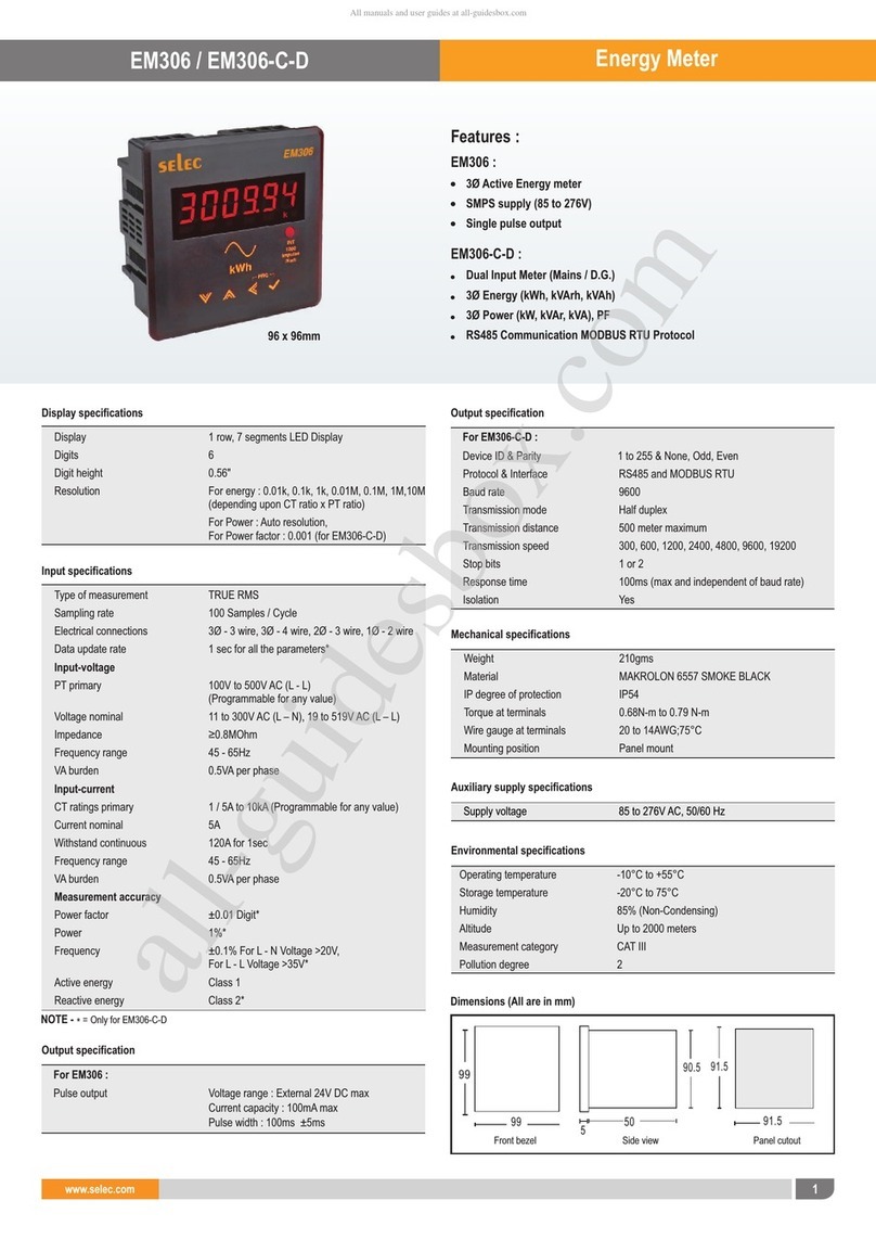
MFM374
Multifunction Meter
OPERATING INSTRUCTIONS
Operating / 1009 / MFM374 / Ver1, OP300-V01.
selec
Creating Best Value
selec
1. INTRODUCTION
1.1 About MFM374.............................................................................................. 01
1.2 Overview........................................................................................................ 02
1.3 Technical Overview........................................................................................ 04
1.4 Installation Guide........................................................................................... 08
1.5 Wiring Guide.................................................................................................. 11
2. HUMAN MACHINE INTERFACE (HMI)............................................................. 15
3. CONFIGURATION.............................................................................................. 21
4. APPLICATIONS................................................................................................. 29
5. COMMUNICATION
5.1 Modbus Parameter....................................................................................... 30
6. USER GUIDE..................................................................................................... 38
7. CONFIG RECORD SHEET................................................................................ 39
Note selec
01
Introduction
ABOUT MFM374
A suitable meter for the measurement of parameters such as voltage, current, power
factor, frequency, power and energy. Features such as pulse output, communication
are available thereby providing a complete solution for many measurement needs.
APPLICATIONS:
1. Electric Automation SCADA System:
MFM374 can be used as Remote Terminal Unit (RTU) for monitoring purpose in a
SCADA System. All measured data is available through RS485 communication
ports with the Modbus Protocol.
2. Energy Management System / Building Management System:
MFM374 can be used to monitor power and energy parameters of an organizations
which can be transmitted to main control room through RS485
3. Heavy Industries:
MFM374 is a suitable meter for heavy industries because of its ability to function
even in rough conditions.
4. Power Transmission and Distribution field
5. Power System Protection Field
6. Industry Automation
7. Large UPS System
Note: Please read this manual carefully & completely before installing /
operating MFM374.
Specifications are subject to change as development is a continuous process
selec
Introduction
02
Ø 3 rows of 4 digits
Ø Network supported: 1Ø-2 wire, 2Ø-3 wire, 3Ø-3 wire, 3Ø-4 wire
ØUser programmable network selection
Ø 7-segment red LED display
Ø Auto / manual page scrolling
ØUser programmable page sequence for page displayed in auto mode
Ø Measures all electrical parameters (True RMS Voltage, True RMS Current, Active
power, Reactive power, Apparent power, Power factor, Frequency,
Active energy, Reactive energy & Apparent energy )
Ø Programmable CT/ PT primary, CT/PT secondary
Ø Memory retention for ten years
Ø Potential free Pulse output for energy
Ø 85 to 270V AC auxiliary supply
Ø RS485 communication (MODBUS Protocol), (Optional)
ØProtection covering for terminal screws
SALIENT FEATURES
ORDER CODE:
Overview
2) MFM 374-C (With communication version)
1) MFM 374
Introduction
Display & Key description
1. 3 lines of seven segment digits in
metering area
Display parameters such as Voltage,
Current, Power factor, Power &
Frequency, Energy
2. Unit (V, A, PF, Hz, kW, kVAr, kVA)
Indicates unit of parameter displayed
Overview
Voltage: V, kV | Current: A, kA
Active Power: kW, MW | Reactive power: kVAr, MVAr
Apparent power: kVA, MVA | Frequency: Hz,
Active energy: kWh, MWh | Reactive energy: kVArh, MVArh
Apparent energy: kVAh, MVAh
3. Keypad: keypad with four dual function keys (HMI or Programming)
4. Display: Bright red LED display for best vision
5. Phase (1, 2, 3, 1-2, 2-3, 3-1) : Display phase to neutral or phase to phase values
selec
03
5
4
1
2
3
selec
7 segment bright red LED display
3 lines, 4 digits per line to show electrical parameters
1 sec for all parameters
LED indication for all electrical parameter such as V, I, PF,
Hz, kW, kVA, kVAr, kWh, kVAh, kVArh, k (kilo), M(mega),
avg, tot, L1, L2, L3
1 Ø-2 wire, 2 Ø-3 wire, 3 Ø-3 wire, 3 Ø-4 wire
Programmable 1A or 5A
100V to 500kV (Programmable for any value)
100 to 500V AC (L-L) Programmable for any value
0.5 VA per phase @ 5A
11 to 300V AC max phase to neutral
19 to 519V AC max phase to phase
Nominal 5A AC (11mA minimum)
6A max (External CT is advised to connect)
1A or 5A to 10,000A (Programmable for any value)
Note: 1A or 5A depends upon the CT secondary
Customized page selection from available standard pages
(selection via configuration menu)
Introduction
04
Description
Display update time
MFM374
Display
LED Indications
Functional Descriptions
Technical Overview
Input Point Electrical Specification
Electrical input type
CT Secondary
Rated input voltage
Rated input current
CT Primary
PT Primary
PT Secondary
Burden
Display Scrolling
Online Pages
Auto / Manual
Frequency range 45 to 65 Hz
selec
Introduction
05
Interface standard &
protocol MODBUS RTU protocol over RS485
General Specification
Pulse Output
Auxiliary Supply
Pulse Output (type)
Operating frequency
Pulse Voltage
Pulse Current
Pulse Width
Power Consumption
Temperature
Humidity
Mounting
Weight
85 to 270V AC/DC
Opto-Isolated
50/60Hz
24V DC max.
100mA max.
100 ms ± 50 ms.
0.5 VA max.@5A per phase
o
Operating temperature: 0 to +50 C
o
Storage temperature: -20 to +75 C
85% RH
Panel mounting
320 gms
Communication address
Transmission mode
Data types
Transmission distance
Transmission speed
Parity
Stop bits
Response time
1 to 255
Half duplex
Float and Integer
500 m maximum
300, 600,1200, 2400, 4800, 9600,19200 (in bps)
None, Odd, Even
1 or 2
100 ms (Independent of baud rate)
Serial Communication (Optional)
selec
Measured values Unit
kW , kW , kW and Total kW
1 2 3
kW
kVA , kVA , kVA and Total kVA
1 2 3
kVA
V
A
Individual and average
-
Hz
kWh
kVAr , kVAr , kVAr and Total kVAr
1 2 3 kVAr
kVArh
kVAh
V1N, V2N, V3N, V12, V23, V31,
Vavg L-N, Vavg L-L
1) For voltage, Current, Power, resolution is automatically adjusted
2) For power factor, resolution is 0.001
Frequency of available phase
Total of all phases
Total of all phases
Total of all phases
kWh Pulse
0.01K
0.1K
1K
0.01M
0.1M
1M
0.01K
0.1K
1K
0.01M
0.1M
1M
Introduction
06
Parameter Measured / Calculated
Parameters
Voltage
I, I, I,I
1 2 3 AVG
Current
Apparent Power
Power Factor
Active Power
Frequency
Reactive Power
Active Energy
Reactive Energy
Apparent Energy
NOTE:
Resolution Table
PT Ratio x CT Ratio
<15
<150
<1500
<15000
<150000
≥1500000
Introduction
Measurement
Voltage VL-N
Voltage V
L-L
Frequency
Active Power
Apparent power
Power factor & Avg Pf
Active energy
Reactive energy
Apparent energy
Current
Average current
Average Voltage L-N
Average Voltage L-L
Reactive Power
Toll free: 1800 227 353
Phone: 91-22-28471 1882 / 4039 4200 / 4039 4202
Email: [email protected]
Accuracy
07
selec
Accuracy
±0.01 PF
Class 1
Class 1
Class 1
Class 1
Class 1
Class 1
±0.5% of F.S. +1 digit
±0.1% for V>20V (L-N)
±0.1% for V>35V (L-L)
selec
Introduction
08
All safety related codifications, symbols and instructions that appear in this operating
manual or on the equipment must be strictly followed to ensure the safety of the
operating personnel as well as the instrument.
If the equipment is not handled in a manner specified by the manufacturer it might impair
the protection provided by the equipment.
CAUTION: Read complete instructions prior to installation and operation
of the unit.
CAUTION: Risk of electric shock.
WIRING GUIDELINES
WARNING:
1. To prevent the risk of electric shock power supply to the equipment must be kept OFF
while doing the wiring arrangement.
2. Wiring shall be done strictly according to the terminal layout. Confirm that all
connections are correct.
3. Use lugged terminals.
4. To eliminate electromagnetic interference use of wires with adequate ratings and
twists of the same in equal size shall be made.
2
5. Cable used for connection to power source, must have a cross section of 1.5mm .
These wires shall have current carrying capacity of 6A.
6. The following safety earth symbol is used in this user’s manual:
Safety Precautions
Installation Guide
Introduction
1. The equipment should be cleaned regularly to avoid blockage of ventilating parts.
2. Clean the equipment with a clean soft cloth. Do not use Isopropyl alcohol or any
other cleaning agent.
Maintenance
CAUTION:
1. This equipment, being built-in-type, normally becomes a part of main control panel
and in such case, the terminals do not remain accessible to the end user after
installation and internal wiring.
2. Conductors must not come in contact with the internal circuitry of the equipment or
else it may lead to a safety hazard that may in turn endanger life or cause electrical
shock to the operator.
3. Circuit breaker or mains switch must be installed between power source and supply
terminals to facilitate power 'ON' or ‘OFF’ function. However this switch or breaker
must be installed in a convenient position normally accessible to the operator.
4. Before disconnecting the secondary of the external current transformer from the
equipment, make sure that the current transformer is short circuited to avoid risk of
electrical shock and injury.
Installation Guidelines
CAUTION:
1. The equipment shall not be installed in environmental conditions other than those
mentioned in this manual.
2. The equipment does not have a built-in-type fuse. Installation of external fuse of
rating 275V AC/1Amp for electrical circuitry is highly recommended.
09
selec
selec
91.5
90.5
50 91.5
Panel CutoutSide view
For installing the controller
1. Prepare the panel cutout with proper dimensions as shown.
EMC Guidelines:
1. Use proper input power cables with shortest connections and twisted type.
2. Layout of connecting cables shall be away from any internal EMI source.
2. Push the meter into the panel cutout. Secure the meter in its place by
pushing the clamp on the rear side. The screws, of the pane of the clamp,
must be in the farthest forward slot.
3. For proper sealing, tighten the screws evenly with required torque.
Tightening torque for clamp: 0.1Nm
CAUTION:
The equipment in its installed state must not come in close proximity to any
heating sources, caustic vapors, oils, steam, or other unwanted process by-
products.
This device contains no user serviceable parts and requires special equipment and
specialized engineers for repair.
NO WARRANTY ON UNIT DAMAGED DUE TO WRONG INPUT / OUTPUT
WIRING CONNECTION.
10
Introduction
99
99
5
Front bezel
Mechanical Installation
EMC Guidelines
SERVICE DETAILS
Introduction
3 PHASE 4-WIRE (COMMONLY USED) WIRING DIAGRAM
3 Ø - 4 wire, 3 CT’s
S2S1 S2S1 S2S1 N
L
N
PULSE
O/P
+
-
+
-
RS485
V2 V3
LN
++
Wiring guide
I1I2I3
V1
MFM374
Terminal Diagram
S2S1S2S1S2S1
N
I1
L1
L2
L3
I2I3
PULSE O/P
L
N
+
11
selec
LOAD
LINE L1
L2
L3
N
N V1
L
O
A
D
V2 V3
RS485
+
12
selecIntroduction
Wiring Guide
3 Ø - 4 wire, 3 CT’s & 3 PT’s
S2S1 S2S1 S2S1 N
L
N
PULSE
O/P
+
-
+
-
RS485
LOAD
LINE L1
L2
L3
N
LN
++
3 PHASE 3-WIRE WIRING DIAGRAM
3 Ø - 3 wire, 2 CT’s & 2 PT’s
S2S1 S2S1 S2S1 V1N
L
N
PULSE
O/P
+
-
+
-
RS485
V2 V3
LOAD
LINE L1
L2
L3
LN
++
I1I2I3
V1 V2 V3
I1I2I3
MFM374MFM374
13
selec
Introduction
Wiring Guide
S2S1 S2S1 S2S1 V1N
L
N
PULSE
O/P
+
-
+
-
RS485
V2 V3
LOAD
LINE L1
L2
N
LN
++
2 Ø - 3 wire, 2 CT’s & 2 PT’s
I1I2I3
S2S1 S2S1 S2S1 V1N
L
N
PULSE
O/P
+
-
+
-
RS485
V2 V3
LOAD
LINE L1
L2
N
LN
++
I1I2I3
MFM374
MFM374
2 PHASE 3-WIRE WIRING DIAGRAM
2 Ø - 3 wire, 2 CT’s
14
selec
Introduction
Wiring Guide
COMMUNICATION WIRING DIAGRAM ( only for MFM374-C )
Master
RS485 to RS232
CONVERTER
+
SHIELDED CABLE
Suggested Terminating resistor
(120 ohm, ¼ watt)
RS485-RS232 Converter
Part no.- AC-RS485-RS232-01
S2S1 S2S1 S2S1 V1N
L
N
PULSE
O/P
+
-
+
-
RS485
V2 V3
LOAD
LINE L1
N
LN
++
1 PHASE 2-WIRE (COMMONLY USED) WIRING DIAGRAM
1 Ø - 2 wire, 1 CT
I1I2I3
MFM374
MFM374
VI
A / M
VAF PE
PRG
K
M
L1
L2
L3
AVG
TOT
VAr
VArh
VL-N
VL-L
Hz
PF
A
W
Wh
VA
VAh
MFM374
VI
A / M
VAF PE
PRG
K
M
L1
L2
L3
AVG
TOT
VAr
VArh
VL-N
VL-L
Hz
PF
A
W
Wh
VA
VAh
MFM374
VI
A / M
VAF PE
PRG
K
M
L1
L2
L3
AVG
TOT
VAr
VArh
VL-N
VL-L
Hz
PF
A
W
Wh
VA
VAh
MFM374
VI
A / M
VAF PE
PRG
VAr
VArh
VL-N
VL-L
Hz
PF
A
W
Wh
VA
VAh
K
M
L1
L2
L3
AVG
TOT
02
03
HMI
Online Page Description
There are 4 dedicated keys labelled as VI, VAF, P, E. Use these 4 keys to read
meter parameters. Simply press these keys to read the parameters.
X1
Press VI ( ) button, the second screen shows:
[ L-L voltage (V 1-2, V 2-3,V 3-1)
X3
Press VI ( ) button, the third screen shows:
[ Current (I1, I2, I3)
Note: In 3Ø-3 wire system only L-L voltage
(V 1-2, V 2-3,V 3-1 ) current (I 1-2, I 2-3, I 3-1 )
&
will be displayed
01
Press VI ( ) button, the first screen shows:
[ L-N Voltage (V1, V2, V3) of all three phases
Note: LED’s of the corresponding parameters on
display, will glow automatically.
MFM374
VI
A / M
VAF PE
PRG
K
M
L1
L2
L3
AVG
TOT
VAr
VArh
VL-N
VL-L
Hz
PF
A
W
Wh
VA
VAh
MFM374
VI
A / M
VAF PE
PRG
K
M
L1
L2
L3
AVG
TOT
VAr
VArh
VL-N
VL-L
Hz
PF
A
W
Wh
VA
VAh
X2
15
selec
MFM374
VI
A / M
VAF PE
PRG
16
selec
HMI
Online Page Description
X3
X2
X1
04
05
06
MFM374
VI
A / M
VAF PE
PRG
K
M
L1
L2
L3
AVG
TOT
VAr
VArh
VL-N
VL-L
Hz
PF
A
W
Wh
VA
VAh
MFM374
VI
A / M
VAF PE
PRG
K
M
L1
L2
L3
AVG
TOT
VAr
VArh
VL-N
VL-L
Hz
PF
A
W
Wh
VA
VAh
K
M
L1
L2
L3
AVG
TOT
VAr
VArh
VL-N
VL-L
Hz
PF
A
W
Wh
VA
VAh
Press VAF ( ) button, the first screen shows:
[ Voltage (L-N), Current of first phase (V1, I1) &
Frequency (Hz)
Note: In 3 Ø-3 wire system only L-L voltage, L-L
current (V 1-2, I 1-2) & Frequency (Hz) will be
displayed
Press VAF ( ) button, the second screen shows:
[ Voltage (L-N), Current of second phase (V2, I2)
& Frequency (Hz)
Note: In 3 Ø-3 wire system only L-L voltage, L-L
current (V 2-3, I 2-3) & Frequency (Hz) will be
displayed
Press VAF ( ) button, the third screen shows:
[ Voltage (L-N), Current of third phase (V3, I3) &
Frequency (Hz)
Note: In 3 Ø-3 wire system only L-L voltage, L-L
current
(V 1-3, I 1-3) & Frequency (Hz) will be displayed
MFM374
VI
A / M
VAF PE
PRG
MFM374
VI
A / M
VAF PE
PRG
MFM374
VI
A / M
VAF PE
PRG
HMI
Online Page Description
X5
X4
X1
08
09
07
K
M
L1
L2
L3
AVG
TOT
VAr
VArh
VL-N
VL-L
Hz
PF
A
W
Wh
VA
VAh
K
M
L1
L2
L3
AVG
TOT
VAr
VArh
VL-N
VL-L
Hz
PF
A
W
Wh
VA
VAh
K
M
L1
L2
L3
AVG
TOT
VAr
VArh
VL-N
VL-L
Hz
PF
A
W
Wh
VA
VAh
Press VAF ( ) button, the fourth screen shows:
[ Average Voltage (L-N), Current of three
phase (V , I ) & Frequency (Hz)
AVG AVG
Note: In 3Ø-3 wire system only AVG L-L voltage,
AVG L-L current, & power factor will be displayed
Press VAF ( ) button, the fifth screen shows:
[ Average Voltage (L-L), Current of three
phase (V , I ) & power factor
AVG AVG
Press P ( ) button, the first screen shows:
[ Power factor of all three phases (PF1, PF2, PF3).
Note: In 3 Ø-3 wire system only AVG power factor
will be displayed
17
selec

Other Selec Measuring Instrument manuals

Selec MX300-1-C-CE User manual

Selec

Selec MX300-1-C-CE User manual

Selec EM306 User manual

Selec

Selec EM306 User manual

Selec MFM376 Series User manual

Selec

Selec MFM376 Series User manual

Selec EM306A User manual

Selec

Selec EM306A User manual

Selec PIC352 User manual

Selec

Selec PIC352 User manual

Selec APFC346 User manual

Selec

Selec APFC346 User manual

Selec MV Series User manual

Selec

Selec MV Series User manual

Selec EM306A User manual

Selec

Selec EM306A User manual

Selec APFC146 User manual

Selec

Selec APFC146 User manual

Popular Measuring Instrument manuals by other brands

Extech Instruments lcr200 user guide

Extech Instruments

Extech Instruments lcr200 user guide

Microchip Technology MCP3901 user guide

Microchip Technology

Microchip Technology MCP3901 user guide

Labgear DAT103 operating manual

Labgear

Labgear DAT103 operating manual

Hama 179555 operating instructions

Hama

Hama 179555 operating instructions

Chauvin Arnoux C.A 1224 user manual

Chauvin Arnoux

Chauvin Arnoux C.A 1224 user manual

Klein Tools ET110 instruction manual

Klein Tools

Klein Tools ET110 instruction manual

Brolight BIM-7001 user manual

Brolight

Brolight BIM-7001 user manual

RR Mechatronics STARRSED TL installation manual

RR Mechatronics

RR Mechatronics STARRSED TL installation manual

London Electronics MAXI-INT2-L Mk.2 manual

London Electronics

London Electronics MAXI-INT2-L Mk.2 manual

Precision Digital Corporation ProtEx PD6870-SS instruction manual

Precision Digital Corporation

Precision Digital Corporation ProtEx PD6870-SS instruction manual

Xylem SI Analytics Lab 955 operating manual

Xylem

Xylem SI Analytics Lab 955 operating manual

Brooks Instrument 0154 Installation and operation manual

Brooks Instrument

Brooks Instrument 0154 Installation and operation manual

Ecom EN3 operating instructions

Ecom

Ecom EN3 operating instructions

Anritsu Spectrum Master MS2720T user manual

Anritsu

Anritsu Spectrum Master MS2720T user manual

Minipa MC-154 instruction manual

Minipa

Minipa MC-154 instruction manual

TSI Incorporated DUSTTRAK DRX 8533 Operation and service manual

TSI Incorporated

TSI Incorporated DUSTTRAK DRX 8533 Operation and service manual

Dillon AP installation instructions

Dillon

Dillon AP installation instructions

FLS FlowX3 F9 Series instruction manual

FLS

FLS FlowX3 F9 Series instruction manual

manuals.online logo
manuals.online logoBrands
  • About & Mission
  • Contact us
  • Privacy Policy
  • Terms and Conditions

Copyright 2025 Manuals.Online. All Rights Reserved.