Selkirk CF User manual
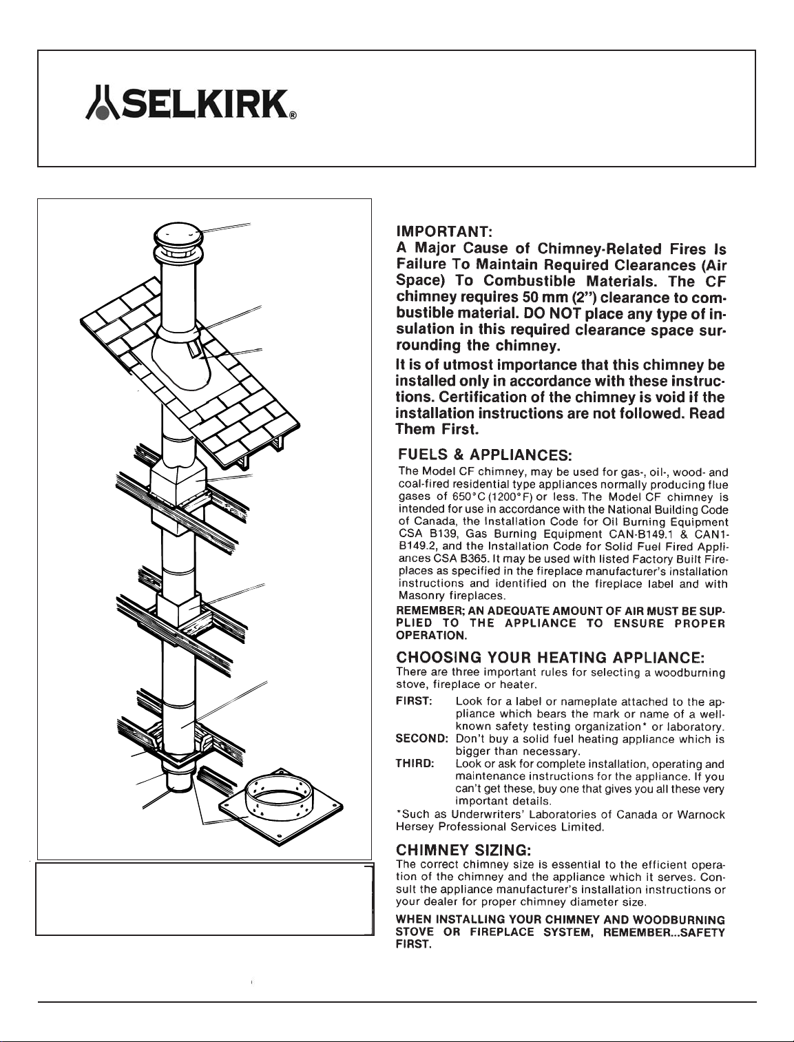
Intermediate Joist
Shield
Any Chimney
Length
Ceiling Support Assembly
Base Cap
Assembly
Lower Bucket
Round Top
Storm Collar
Flashing
Attic Insulation
Shield/Firestop
Spacer
These installation requirements are based on complete tests of the Model CF Chimney
in accorance with the Standard for 650 deg. C Factory-Built Chimneys
CAN/ULC-S629-M87.
Selkirk chimney parts are produced under the Listing Program of Underwriers
Laboratories of Canada. Each ULC Listed part carries the label specified in their
“List of Equipment and Materials”.
Manufactured by Selkirk Canada Corp. - Hamilton, Ontario
Installation Instructions for
MODEL CF
CEILING SUPPORTED
CHIMNEY
880063LT-rev.0711
GENERAL INSTALLATION RULES:
1. Situate the chimney in the structure so that it can be installed
without cutting joists, sills, plates or load bearing partitions or
members.
2. Each wood or coal appliance should have its own chimney.
DON’T INTERCONNECT.
3. There should be no draft regulators on solid fuel equipment
and smoke pipes and cleanout caps should be tight.
4.Aminimum smoke pipe length of 1 m (3 ft.) between appliance
and chimney is recommended.
5. Continuous operating flue gas temperature should not exceed
650°C (1200°F).
CREOSOTE AND SOOT FORMATION AND NEED
FOR REMOVAL:
When wood is burned slowly, it produces tar and other organic vapors,
which combine with expelled moisture to form creosote. The creosote
vapors condense in the relatively cool chimney flue of a slow-burning
fire. As a result, creosote residue makes an extremely hot fire.
With coal, which can burn with a smoky fire, this smoke also condenses
in the chimney to form soot.
The chimney should be inspected at least once every 2 weeks during
the heating season to determine if a creosote or soot buildup has
occurred.
If creosote has accumulated, it should be removed to reduce the risk of
chimney fire.
If you see deposits more than 1/16 inch thick, clean all of the chimney
parts mechanically. This means using brushes, scraping or equivalent.
Don’t start a chimney fire! With only slight deposits, try a hot fire to see
if the black deposits change to light ash, or fall down the chimney and
the inside of the appliance for deposits. Do not use chemical cleaners,
they may corrode the inside of the chimney. They may or may not
prevent or remove creosote. When they are used together with a hot
fire, it is probably the fire that is doing the work.
Depending on the rate of buildup, as you learn what is going on in the
chimney, you can adjust your cleaning schedule.
If you have any doubts about your ability to clean the chimney, of if the
deposits are very heavy and hard to remove, call a professional
chimney sweep. Do not try to burn them off.
It doesn’t matter how careful you are with loading, fuel wood selection
or draft control, you should observe the above precautions with any
wood stove or chimney installation.
CHIMNEY FIRES
AND WHAT TO DO ABOUT THEM
Your Selkirk Model CF Chimney is not intended or designed
for use as a combustion or fire chamber. It is very easy to overfire
your woodburning appliance with kindling, scrap lumber, brush or
any fast burning fuel. This can produce flames and high
temperatures all the way up the chimney, and may cause chimney
damage.
If you see your appliance or the smoke pipe glowing red, you are risking
chimney damage, or a fire. The creosote may be burning inside the
chimney. If you see flames coming out of the top, you are either
overfiring or there is a chimney fire.
If the fire in your heater has gotten out of control, or if you suspect a
chimney fire for any reason, follow these steps:
1. Immediately close all dampers and/or air entrance openings to your
appliance. This includes doors on Franklin type stoves. Block off
fireplace openings.
2. Alert your family to the possible danger.
3. Inspect your appliance and chimney surroundings for possible fire. If
in doubt, alert your fire department.
4. Do not continue to use your appliance until it and your chimney have
been thoroughly inspected. Overheating can cause metal parts to
expand, buckle and crack. If you are not certain, have a qualified
heating man disassemble all parts so they can be inspected and
replaced.
5. Do not use salt or water on the fire in your appliance. Salt is corrosive
and water will cause a danger steam explosion. You might be able to
control the fire by using ashes, sand or baking soda, since baking soda
is an ingredient used for dry chemical fire extinguishers.
6. After a chimney fire, when it is safe to do so, check internal locations
such as the attic and under the roof and keep watching for two or three
hours. There may be delayed smoldering and subsequent ignition,
even if the fire inside the chimney has been controlled.
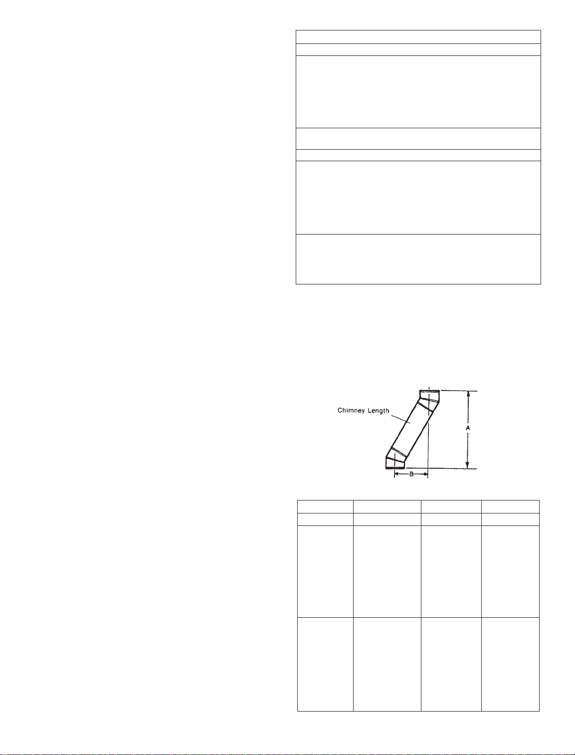
CHIMNEY OFFSETS:
One pair of (2) 15° or 30° elbows can be used to provide a sloped
offset. The maximum permissible angle with solid fuel installation is 30
degrees.
An offset data table is supplied to determine the offset desired and the
offset height.
Table 1. Framing and Support Table
Model CF Chimney
Inside Diameter 6” 7” 8”
Outside Diameter 267mm (10-1/2”) 299mm (11-3/4”) 330mm (13”)
Enclosure Framing
(Square) 369mm (14-1/2”) 400mm (15-3/4”) 432mm (17”)
* Ceiling Support
Framing (Square) 362mm (14-1/4”) 362mm (14-1/4”) 362mm (14-1/4”)
Approx. weight
kg/m (lbs/ft.) 11.5 (8) 13.5 (9) 15.5 (10.5)
Maximum Height for all supporting methods
Ceiling Support Package 12m (40’)
Interior Resupport Assembly/
Offset Support 9 m (30’) All Sizes
Wall Support Package 12 m (40’)
Roof Support 9 m (30’)
Minimum Clearance to combustibles 50 mm (2” ) all sizes
* The clearance to combustibles obtained with a correctly installed Ceiling
Support Assembly in the framed opening specified has been tested. The 2”
clearance does not apply at this location.
}
Table 2.
6” Dia 7” Dia 8” Dia
Elbow Length A B A B A B
2 x 15° 9” 76mm 457mm 473mm 400mm 473mm 483mm
(3¾”) (18½”) (3-5/8”) (18-7/8”) (3-5/8”) (19¼”)
2 x 15° 12” 102mm 191mm 105mm 508mm 112mm 530mm
(4½”) (20-3/8”) (4-1/8”) (20¾”) (4-1/8”) (20-7/8”)
2 x 15° 18” 143mm 714mm 127mm 660mm 127mm 660mm
(5-5/8”) (28-1/8”) (5¾”) (26½”) (5¾”) (26¾”)
2 x 15° 36” 264mm 1114mm 254mm 1121mm 254mm 1118mm
(10-3/8”) (43-7/8”) (10½”) (44-1/8”) (10½” (44½”)
2 x 30° 9” 187mm 495mm 203mm 537mm 200mm 543mm
(7-3/8”) (19-1/2”) (8”) (21-1/8”) (7-7/8”) (21-3/8”)
2 x 30° 12” 225mm 559mm 235mm 600mm 238mm 608mm
(8-7/8”) (22”) (9-1/4”) (23-5/8”) (9-3/8”) (23-7/8”)
2 x 30° 18” 302mm 695mm 311mm 737mm 314mm 743mm
(11-7/8”)
(27-3/8”) (12-1/4") (29”)
(12-3/8”) (29-1/4”)
2 x 30° 36” 530mm 1089mm 540mm 1130mm 543mm 1137mm
(20-7/8”) (42-7/8”) (21-1/4”) (44-1/2”) (21-3/8”) (44-3/4”)
Page 3
A
B
Attic
Insulation Shield/
Firestop Spacer
Attic Insulation
Shield/ Firestop Spacer Intermediate
Joist Shield
50mm (2")
Clearance
Enclosure Walls
Smoke
Pipe Ceiling Support Assembly
with Base Cap Assembly
Ceiling Support Assembly
with Base Cap Assembly
Smoke
Pipe Smoke
Pipe
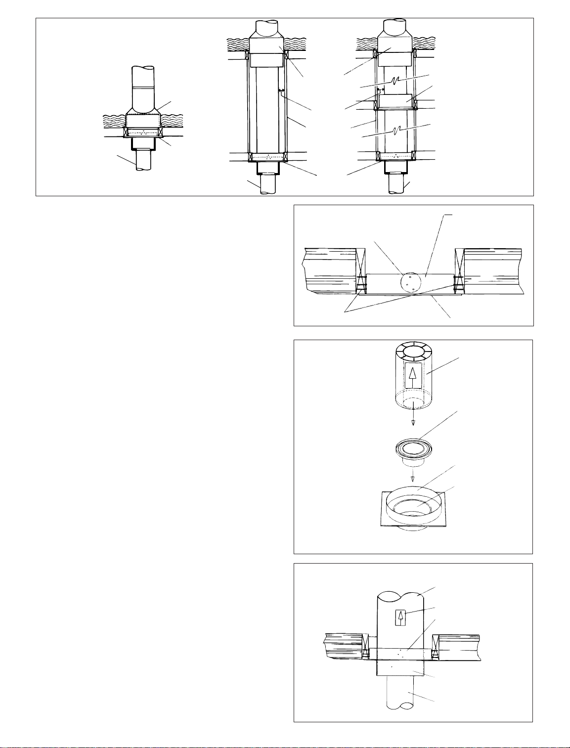
CEILING SUPPORT ASSEMBLY (See Figure 4)
1. Totally frame (all 4 sides) a level square opening with inside
dimensions 362mm (14 1/4”) square.
2. With the Lower Bucket removed, place the Ceiling Support
Assembly into the framed opening from below.
3. Drive one nail, 1-1/2” common or spiral, part way into each of
the four (4) nailing areas of the support. Check that the trim
plate is level and flush. (Figure 5)
4. Finish nailing through all pre punched holes. (12 nails total)
5. Replace the Lower Bucket. Insert the Basecap Assembly in
the bottom of the first chimney length (Figure 6).
6. Lower the first chimney length into the Lower Bucket. Ensure
the Basecap Assembly is located inside the base of the
chimney and the chimney length rests on the Lower Bucket.
(Figure 6 & 7)
NOTE: Any length of CF Chimney can be used. There is no
special “starter” length required with this Ceiling Support.
7. Additional chimney lengths may now be installed above this
support to a total height of 12 m (40”).
8. Continue the chimney installation as specified in the CF
Chimney Installation Instructions.
Ceiling Support Assembly
Trim Plate
Nails
Prepunched Hole Area
Chimney Length
Basecap Assembly
Installed in Bottom
of first chimney length
and then lowered into
the lower bucket
Ceiling Support
Assembly
Lower Bucket
Figure 5.
Figure 4.
Typical Ceiling Supported
Installations
Figure 6.
Figure 7. Chimney
Length
Label
Ceiling Support Assembly
Lower
Bucket
Smoke
Pipe
Method of assembly showing how the first chimney length is installed in the
ceiling support.
Page 4
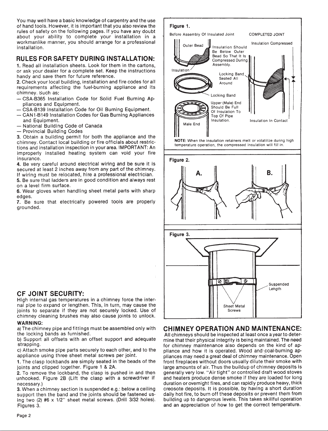
SMOKE PIPE ADAPTER INSTALLATION:
1. The stub end of the adapter is intended to fit inside of the smoke
pipe from a solid fuel appliance, thus preventing condensate drips
at the chimney connection. See Figure 8.
2. Secure the smoke pipe from the appliance to the smoke pipe
adapter using 3 sheet metal screws per joint.
IMPORTANT: CF chimney ceiling supports have been
temperature tested using a vertical single wall connector. Ceiling
surface temperatures within and around the support were within
limits allowable in accordance with ULC Standard S629. These
tests establish that connector clearances to combustible may be
less than those permitted for untested connector installations.
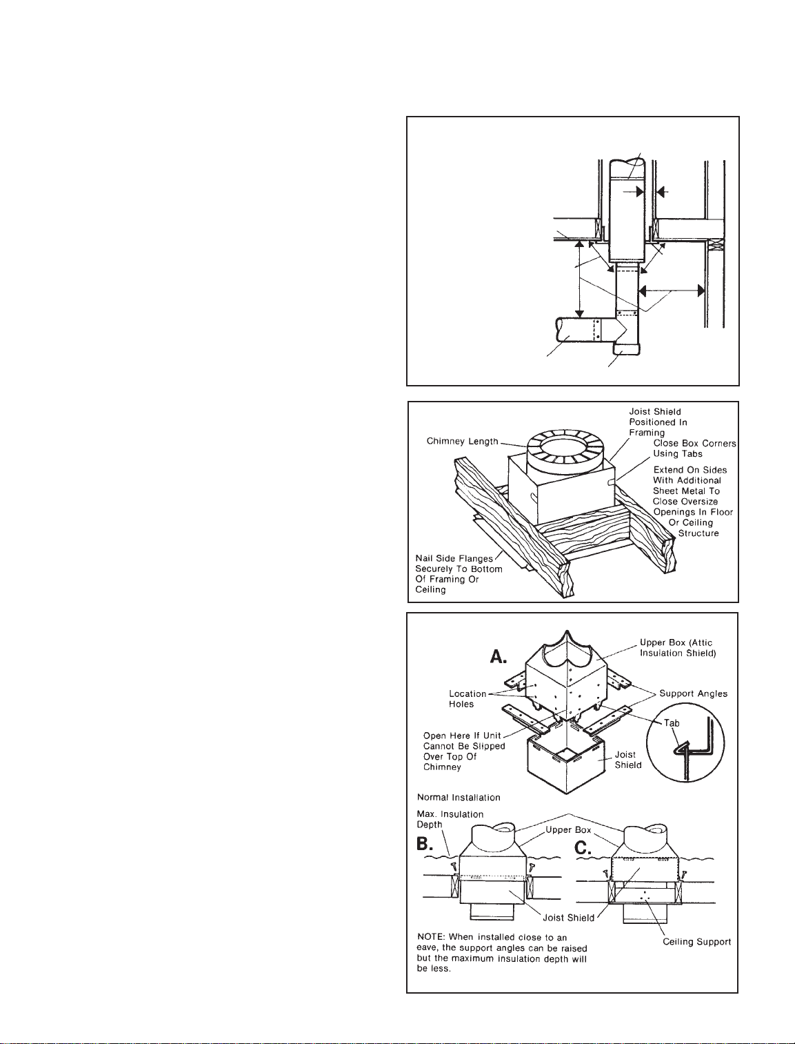
INTERMEDIATE JOIST SHIELD
INSTALLATION (See Figure 9)
This shield protects and firestops the floor joist of a house where
there is no insulation resting above the floor nor any intention of
insulation being put in.
1. Fully frame a level square opening (all four sides) for 50 mm (2”)
clerance from the outside of the chimney to the inside of the
frame. 6” – square opening 369 mm (14 1/2”)
7” – square opening 400 mm ( 15 3/4”)
8” – square opening 432 mm (17”)
2. Place the joist shield up into the framed opening.
3. Nail the side flanges into the framing or ceiling for stability.
4. If the framed opening is larger than necessary, the joist shield
outer edges must be extended by appropriate means (attaching
metal plates, 28 gauge galvanized steel or heavier) to completely
block the framed opening from any vertical air flow around the
chimney (chase installation).
5. Ceiling material can be placed over the joist shield edges,
provided 50 mm (2”) minimum clearance is maintained from the
chimney pipe.
6. Enclose the chimney when accessible to prevent any accidental
contact with the chimney.
INSTALLATION OF THE ATTIC INSULATION
SHIELD/FIRESTOP SPACER:
This sheild has three main components and is very versitile, as will
be illustrated below. The shield must be used at a ceiling level
entering an attic to prevent insulation from coming into contact
with the chimney. It also firestops this level and because it is a
firestop, DO NOT CUT the upper box.
1. Fully frame a level square opening (all four sides) for 50 mm (2”)
clearance from the outside of the chimney to the inside of
the frame.
6” – square opening 369 mm (14 1/2”)
7” – square opening 400 mm ( 15 3/4”)
8” – square opening 432 mm (17”)
2. Remove the joist shield from the inside of the attic insulation
shield (upper box).
3. Attach the joist shield to the inside tabs of the upper box. Bend
the tabs up to secure the two together.
4. Place the support angles in the most convenient set of holes
provided (with overlapping edges up, Figures 10A & B) and lower
the complete assembly over the chimney. If necessary, unscrew
the assembly to surround the chimney.
5. Nail securely into place on all four sides.
6. If the attic insulation shield (upper box) is to be used over a
ceiling support, leave the joist shield inside the upper box. The
support angles can then be installed as shown in Figure 10C.
NOTE: It is mandatory that an attic insulation shield be used.
Use locking bands at
every joint
2” min.
[50mm]
See
Note 2
See Note 1
Connector (or smoke pipe)
Drip free cap on cleanout tee
NOTE:
1. Refer to installation codes for
clearances to single wall pipe.
(Normally 450 mm (18”)
minimum cearance is required.
2. The purpose of the diagonal
arrows is to show that the
450mm (18”) clearances DOES
NOT APPLY to the vertical
connector entering a Ceiling
Support.
Ceiling
Figure 8. Connection to Lower End
Of Ceiling-Supported Chimney
Figure 9. Intermediate Joist Shield
Installation
Figure 10.
Any Chimney Length
Page 5
Round Top
Chimney Lengths
Locking Band
Storm Collar
Roof Flashing
50 mm (2") Minimum
Clearance To
Combustible Material
Roof Brace Kit
Additional Lateral Support For
Chimneys More Than 1.8 m (6')
Above Roof
Attic
Figure 12.
Page 6
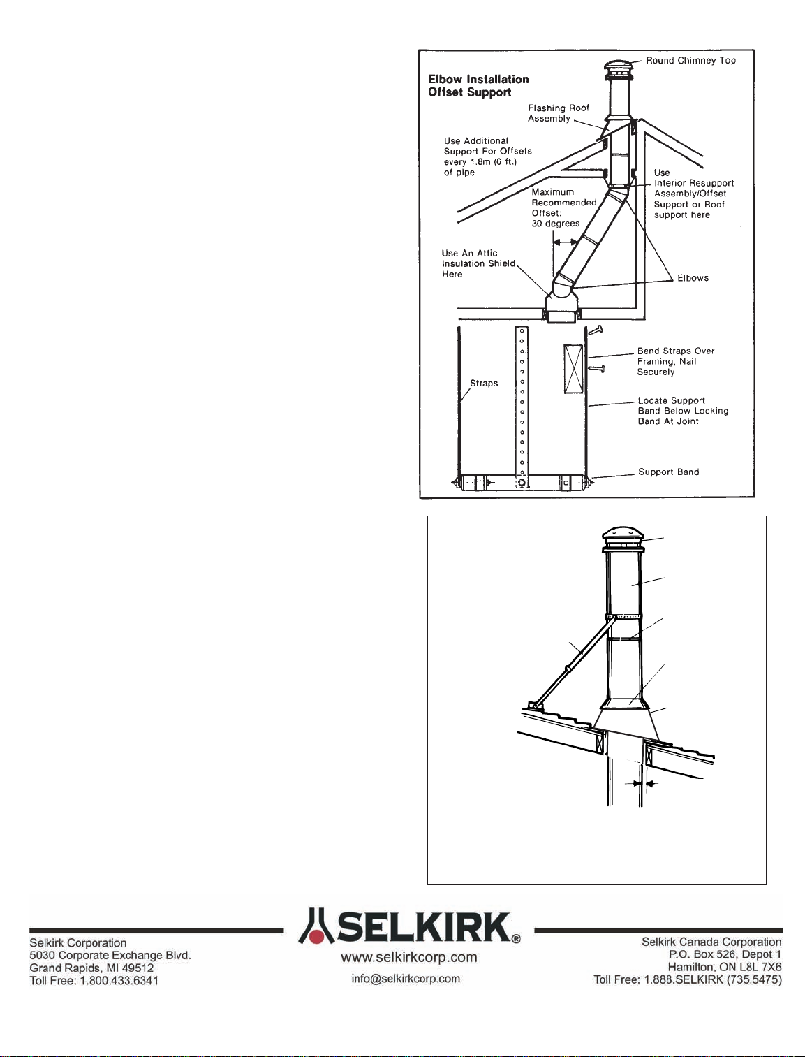
INSTALLED ELBOWS & INTERIOR
RESUPPORT ASSEMBLY / OFFSET SUPPORT
INSTALLATION (See Figure 11)
Two pairs of (four) 15 or 30 degree elbows may be used to provide
an offset in order to avoid cutting of joists and to clear other
obstructions. Offsets are within the house envelope only.
The Maximum Permissible Angle With Solid Fuel Installation is 30
Degrees.
1. The last vertical run of chimney above an offset must be
resupport using an Interior Resupport Assembly/Offset Support.
2. Securely clamp it to the pipe just above a locking band.
3. The straps are then run along the OUTSIDE of the joists and
nailed to them using 1 1/2"nails, 2 per strap.
The weight carrying capacity of the support, which depends on the
angle of the straps, and the security of attachment is adequate for
9 m (30') of Model CF Chimney pipe.
ENCLOSURE OF CHIMNEY:
The chimney must be enclosed when installed in an accessible
area to prevent damage and personal contact.
Enclosure walls should have a fire rating equal to or greater than
that required for the floors or ceilings through which the chimney
passes except in single or two family dwellings. Remember to
maintain a 50 mm (2") minimum air space clearance to any
combustible material.
ROOF FLASHING
INSTALLATION (See Figure 12)
1.Onceyouhavemarkedwherethechimneywillpenetratethrough
the roof, center, position and prepare the roof area.
2. Frame a RECTANGULAR opening to suit the pitch of the roof
and ensure that a 50mm (2") clearance is maintained to all
combustibles.
3. Finish the chimney off to its proper height. Chimneys are
required to extend at least 900 mm (3') above the highest point
where they pass through the roof of a building and at least 600
mm (2') higher than any portion of a building within 3 m (10').
4. Place the roof flashing suitable for the roof pitch over the
chimney casing and nail (1 1/2"common or spiral nails) securely
to the roof, top end (nearest roof peak) UNDER shingles, lower
end OVER shingles to provide a watershed.
5. Apply a 1/4"bead of suitable grey or white caulking compound
just above the top of the flashing cone on the chimney casing.
Slide the storm collar downward through the applied compound
and into position to ensure a waterproof joint. Apply additional
caulking compound above the storm collar as required.
6. If the chimney extends more than 1.8 m (6') above the roof, a
roof brace kit is required. See installation instructions packaged
with it.
7. Install a round top (see instructions packaged with the round
top). The round top prevents entry of moisture which might lead to
premature deterioration of the chimney.
8. The chimney may be painted with a heat resistant paint. To
improve adhesion to the Model CF chimney, degrease, dry and
follow the paint manufacture's application instructions. Refer to
their Paint Warranty (if applicable).
Figure 11.
Table of contents


