SellEton Scales PS-IN202SS User manual
Version 2013.08
PS-IN202SS
Weight Indicator
User’s Manual

PS-IN202SS Indicator - 1 - V2015.05
Contents
FRONT VIEW OF THE INDICATOR
CHAPTER 1 CONNECTIONS
1.1 WHAT'S IN THE BOX
1.2CONNECTING TO THE WEIGH PLATFORM
1.3CONNECTION TO A PRINTER OR COMPUTER
1.4CONNECTION TO THE POWER SUPPLY
CHAPTER 2 CONFIGURATION
2.1 SET UP (“P”) MENU
2.2 Setup Menu Chart
2.3 Exiting the setup menu
2.4 USER (“S”) MENU
2.5 User Menu Chart
2.6 Setup Menu Descriptions
2.7 User Menu Descriptions
CHAPTER 3 CALIBRATION
3.1 Zero Calibration
3.2 Span Calibration
3.3 View calibration values
3.4 Key-in zero calibration value
3.5 Key-in span calibration value
CHAPTER 4 OPERATION
4.1 Display
4.2 Display Details
4.3 Keyboard
4.4 Weighing
4.5 Tare Function
PS-IN202SS Indicator - 2 - V2015.05
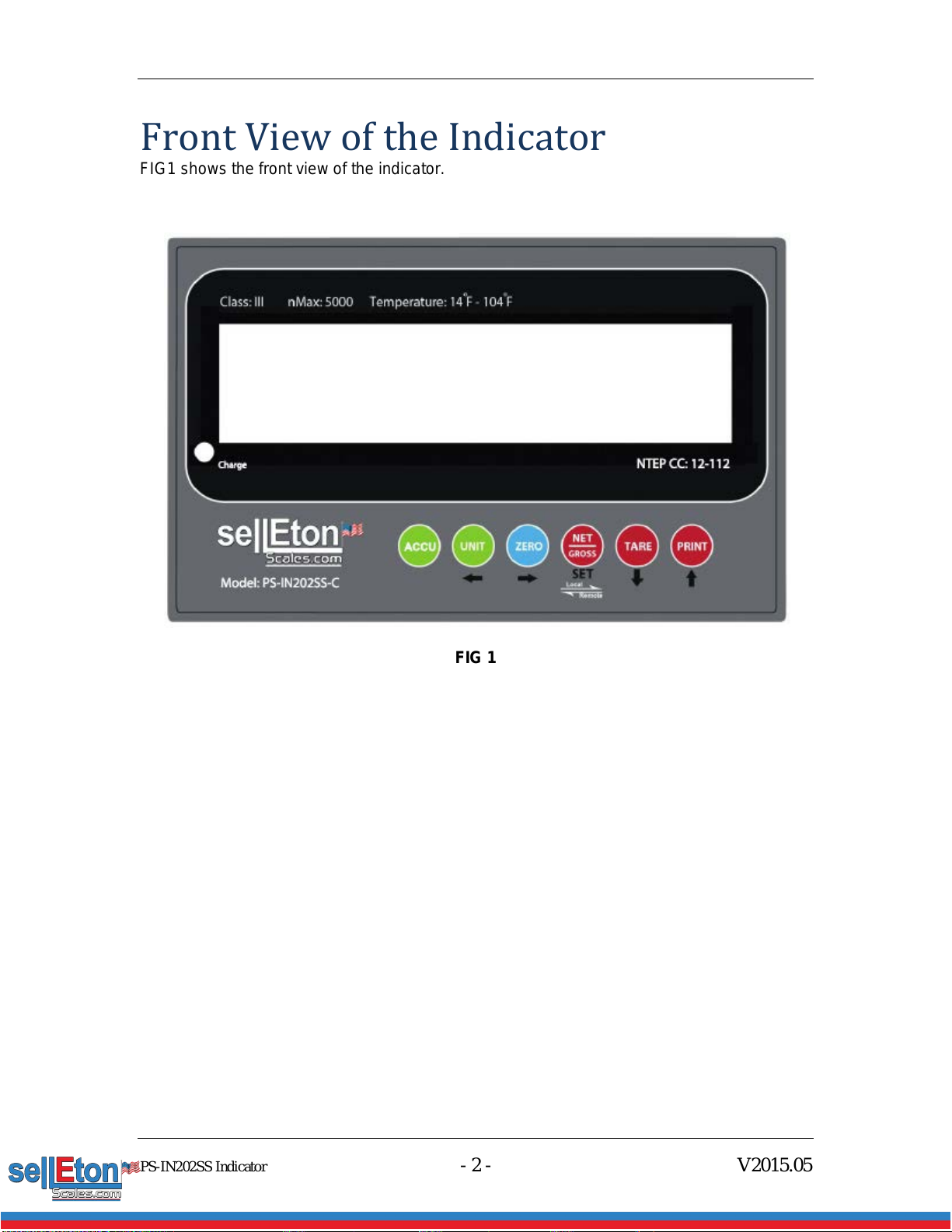
Front View of the Indicator
FIG1 shows the front view of the indicator.
FIG 1

PS-IN202SS Indicator - 3 - V2015.05
Chapter 1
Connections
1.1 WHAT'S IN THE BOX
The box contents are as follows:
Indicator
Screws and knobs
Wall Mount Bracket
15 ft cable
This Manual
The indicator is supplied with a 15 ft shielded load cell cable to interface to weigh platform’s
load cell(s) or junction box.
1.2 CONNECTING TO THE WEIGH PLATFORM
a. Open the back cover of the indicator and you will find two channel connectors as shown
below in FIG 2. Assemble the cables with the pin assignments shown in FIG 2:
FIG 2
1.3 CONNECTION TO A PRINTER OR COMPUTER
The indicator contains a standard full duplex RS-232 serial port, designed for connection to
either a PC or a serial printer. Connect the serial cable as instructed in FIG 2.
Pin No. Pin Name
1.4 CONNECTION TO THE POWER SUPPLY
The indicator comes with a power cable attached to the indicator. When the power cable is
plugged in, the built-in battery is being recharged. The “recharge” light will be on. We
strongly recommend recharging the indicator for at least 12 hours before the first-time use.

PS-IN202SS Indicator - 4 - V2015.05
Chapter 2
Configuration
The indicator contains two main setup menus:
The Setup (“P”) menu
This configures the indicator to the weigh platform
The User (“S”) menu
This configures the serial communication port and enables some user options.
The Setup and User menus consist of several menu selections, each with its own sub-menu.
To set up the indicator, first select the appropriate menu mode. Keys [UNIT], [ZERO],
[TARE] and [PRINT] become direction navigators (as indicated by the arrows above them)
to move around the menus and the [NET/GROSS] key is used to save or SET the
selections.
2.1 SET UP (“P”) MENU
a. Switch off the indicator.
b. On the rear panel, move the Calibration/Setup Switch to the “Setup” position. Up is the
calibration mode, down is the weighing mode.
c. Switch on the indicator. The indicator will display “P 1” to indicate that it is in Setup P
menu mode.
d. Choose the channel you are working on. The default channel is 1. You can press and
hold [NET/GROSS] to switch between Channel 1 and 2. When it is on Channel 2 mode,
there is a “2” shown on the right upper corner of the screen.
Use the direction keys to navigate around in the Setup Menu Chart.
a. To move to a new “P” heading, use the [TARE] (down) or [PRINT] (up) key to navigate
the Setup Menu Chart.
b. To move to the selection level, press the [ZERO] (right) key once. The current saved
selection is shown.
c. To view the available selections for the current “P” heading, use the [TARE] (down) or
[PRINT] (up) key to navigate through the selection field.
d. To save a new selection, press the [NET/GROSS] (Set) key .To exit without saving, press
the [UNITS] (left) key to return to the current “P” heading.
e. Repeat Steps 1 through 4 until the Setup Menu is programmed.

PS-IN202SS Indicator - 5 - V2015.05
FIG 3
2.2 Setup Menu Chart
FIG 4
The User (“S”) sub-menus appear when scrolling left or right from the “P” menu. Some
selections shown are not available on some versions.
2.3 Exiting the setup menu
a. Switch off the indicator.
b. On the rear panel, move the Calibration/Setup Switch to the “Calibration” position. Up is
the calibration mode. Down is the weighing mode.
c. Switch on the indicator. The display will go through a digit check then go into Normal
Operating mode. All front panel keys will now return to their normal mode of operation.
d. Choose the channel you are working on. The default channel is 1. You can press and
hold [NET/GROSS] to switch between Channel 1 and 2. When it is on Channel 2 mode,
there is a “2” shown on the right upper corner of the screen.
2.4 USER (“S”) MENU
a. Enter the Setup (“P”) menu.
PS-IN202SS Indicator - 6 - V2015.05
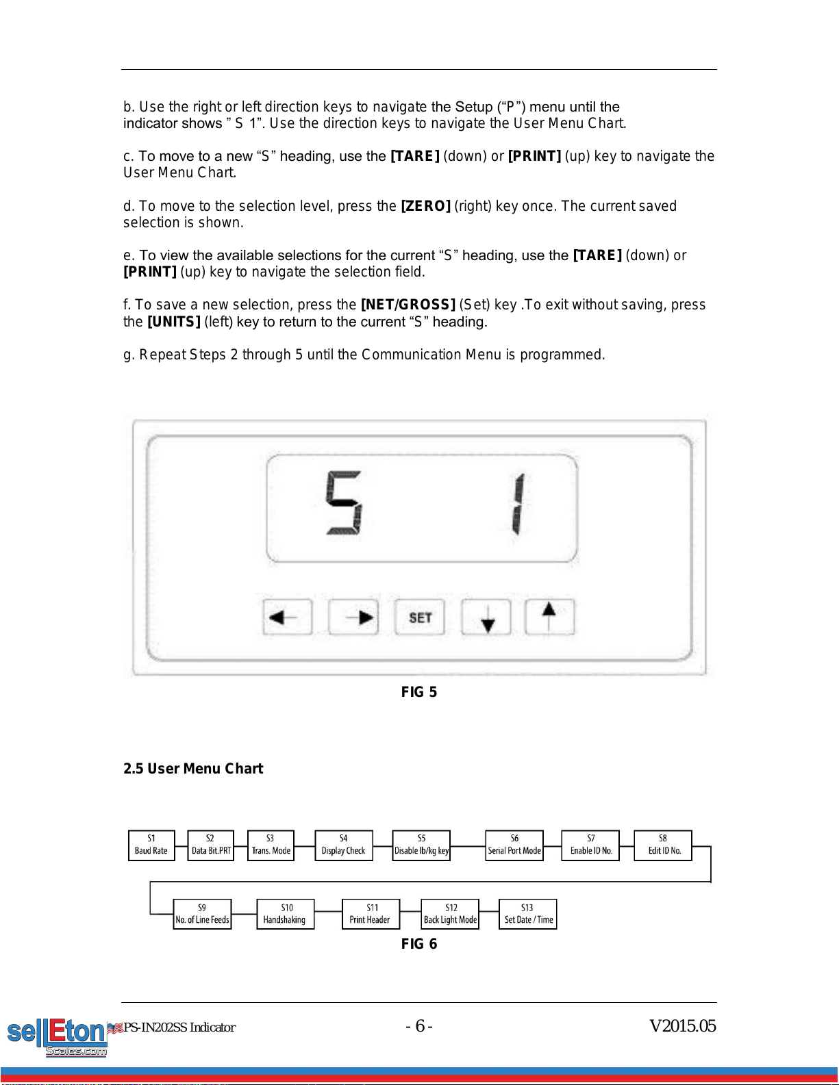
b. Use the right or left direction keys to navigate the Setup (“P”) menu until the
indicator shows ” S 1”. Use the direction keys to navigate the User Menu Chart.
c. To move to a new “S” heading, use the [TARE] (down) or [PRINT] (up) key to navigate the
User Menu Chart.
d. To move to the selection level, press the [ZERO] (right) key once. The current saved
selection is shown.
e. To view the available selections for the current “S” heading, use the [TARE] (down) or
[PRINT] (up) key to navigate the selection field.
f. To save a new selection, press the [NET/GROSS] (Set) key .To exit without saving, press
the [UNITS] (left) key to return to the current “S” heading.
g. Repeat Steps 2 through 5 until the Communication Menu is programmed.
FIG 5
2.5 User Menu Chart
FIG 6

PS-IN202SS Indicator - 7 - V2015.05
2.6 Setup Menu Descriptions
This section provides a more detailed description of the selections found in the Setup Menu
Chart. Factory-set defaults are shown in bold with a checkmark (√).
NAME/CODE
DESCRIPTION
CODE/VALUE
P1
Capacity
Full capacity of the scale. Value should be consistent with legal
requirements and environmental limits on the useful system resolution.
6.0000√
P2
Accuracy
Accuracy of the scale. Value should be consistent with legal requirements
and environmental limits on the useful system resolution.
Dynamic
P3
Span
Span Gain is related to the A/D integration time. The larger the span, the
higher the internal resolution, but the slower the update speed. Note that
the scale must be recalibrated whenever this parameter is altered. See
Appendix C for more information.
10√
80
P4
Zero Track
Band
Selects the range within which the scale will automatically zero. Note that
the scale must be in standstill to automatically zero. Selections are in
Display Divisions.
0d
0.5d√
1d, 3d, 5d
P5
Zero Range
Selects the range within which the scale may be zeroed. Note that the
indicator must be in standstill to zero the scale.
100%√
1.9%, 2%, 20%
P6
Power on
Zero Range
Set the zeroing range after the indicator powers on.
0 means deactivate Power On Zeroing
0, 2%, 3%,
20% √100%
P7
Motion Band
Sets the level at which motion is detected by comparing the present
display update with the previous one. If motion is not detected for two
seconds or more, the scale is in standstill and can process a Print or Zero
command. Maximum value varies depending on the local regulations.
1d√
3d,
5d
10d
P8
Digital Filter
Averages weight readings to produce higher stability. The higher the filter
setting the greater the stability but the slower the indicator’s response
time. Choose Med unless a very fast response is needed
FAST
MED√
SLOW
P9
Overload
Limit
Selects the desired formula which determines the point at which the
indicator shows overload. All selections are based on the primary unit
selected in P8
“FS” = Full Scale in primary units
FS
FS+ 2%√
FS + 1d
FS + 9d
P10
Calibration
Unit
Selects the primary base unit to be used in the calibration process. Also
the default unit for normal operation.
“1” = calibration unit is lb “2” = calibration unit is kg
1√
2
P11
Zero
Calibration
Places the indicator into the zero calibration routine. Scrolling down with
the [ZERO] key one level begins the procedure
Press [ZERO] key to
begin sequence
P12
Span
Calibration
Places the indicator into the span calibration routine. Scrolling down with
the [ZERO] key one level begins the procedure
Press [ZERO] key to
begin sequence
P13
View
Calibration
Actuates the function that allows the user to view both the zero and span
calibration value. The values displayed in this function are valid only after
calibration (P11 and P12) have been successfully completed. Scrolling
down with the [ZERO] key one level begins the procedure
Press [ZERO] key to
begin sequence
P14
Key-in Zero
Allows the user to key in a known zero calibration value in case of memory
loss in the field. Scrolling down with the [ZERO] key one level begins the
procedure
Press [ZERO] key to
begin sequence
P15
This sub menu will reset all parameters in the “P” and “S” menu to the
default setting. USE WITH CAUTION!
Press [ZERO] key twice
to begin sequence
PS-IN202SS Indicator - 8 - V2015.05
Factory
Reset
P16
Normal/Slave
Mode Setting
Set the indicator to be normal or slave mode. “n” means normal; “s”
means slave. Connect the indicator through RS232 with another indicator
to be used an additional display for “slave mode”.
N√
S
P17
Counting
Mode setting
Activate / deactivate the counting mode. “1” is ON, “0” is OFF
0
1√
P18
Animal Mode
Set the divisions for animal weighing hold function
XXd
P19
Accumulation
(SS Only)
Set accumulation modes: Automatic or Manual
In Automatic mode, it saves weights automatically when it is stable.
Auto
Man√
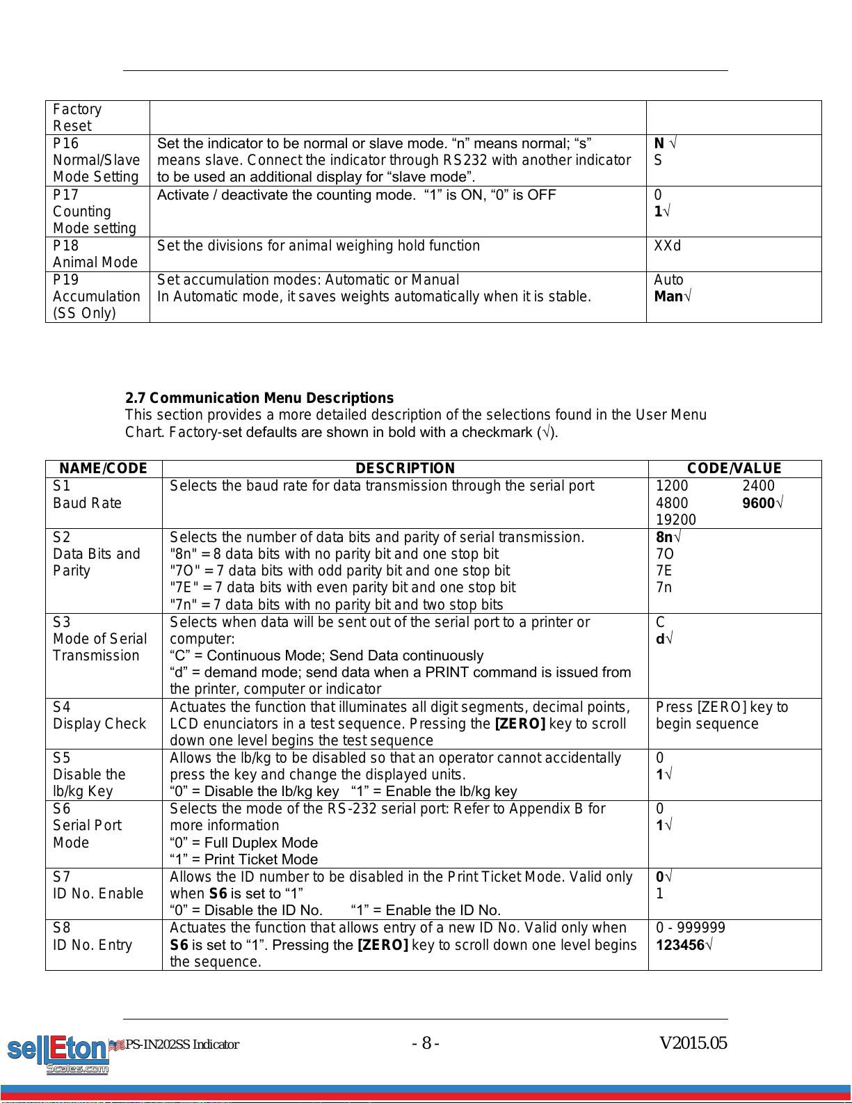
2.7 Communication Menu Descriptions
This section provides a more detailed description of the selections found in the User Menu
Chart. Factory-set defaults are shown in bold with a checkmark (√).
NAME/CODE
DESCRIPTION
CODE/VALUE
S1
Baud Rate
Selects the baud rate for data transmission through the serial port
1200
4800
19200
2400
9600√
S2
Data Bits and
Parity
Selects the number of data bits and parity of serial transmission.
"8n" = 8 data bits with no parity bit and one stop bit
"7O" = 7 data bits with odd parity bit and one stop bit
"7E" = 7 data bits with even parity bit and one stop bit
"7n" = 7 data bits with no parity bit and two stop bits
8n√
7O
7E
7n
S3
Mode of Serial
Transmission
Selects when data will be sent out of the serial port to a printer or
computer:
“C” = Continuous Mode; Send Data continuously
“d” = demand mode; send data when a PRINT command is issued from
the printer, computer or indicator
C
d√
S4
Display Check
Actuates the function that illuminates all digit segments, decimal points,
LCD enunciators in a test sequence. Pressing the [ZERO] key to scroll
down one level begins the test sequence
Press [ZERO] key to
begin sequence
S5
Disable the
lb/kg Key
Allows the lb/kg to be disabled so that an operator cannot accidentally
press the key and change the displayed units.
“0” = Disable the lb/kg key “1” = Enable the lb/kg key
0
1√
S6
Serial Port
Mode
Selects the mode of the RS-232 serial port: Refer to Appendix B for
more information
“0” = Full Duplex Mode
“1” = Print Ticket Mode
0
1√
S7
ID No. Enable
Allows the ID number to be disabled in the Print Ticket Mode. Valid only
when S6 is set to “1”
“0” = Disable the ID No. “1” = Enable the ID No.
0√
1
S8
ID No. Entry
Actuates the function that allows entry of a new ID No. Valid only when
S6 is set to “1”. Pressing the [ZERO] key to scroll down one level begins
the sequence.
0 - 999999
123456√
PS-IN202SS Indicator - 9 - V2015.05
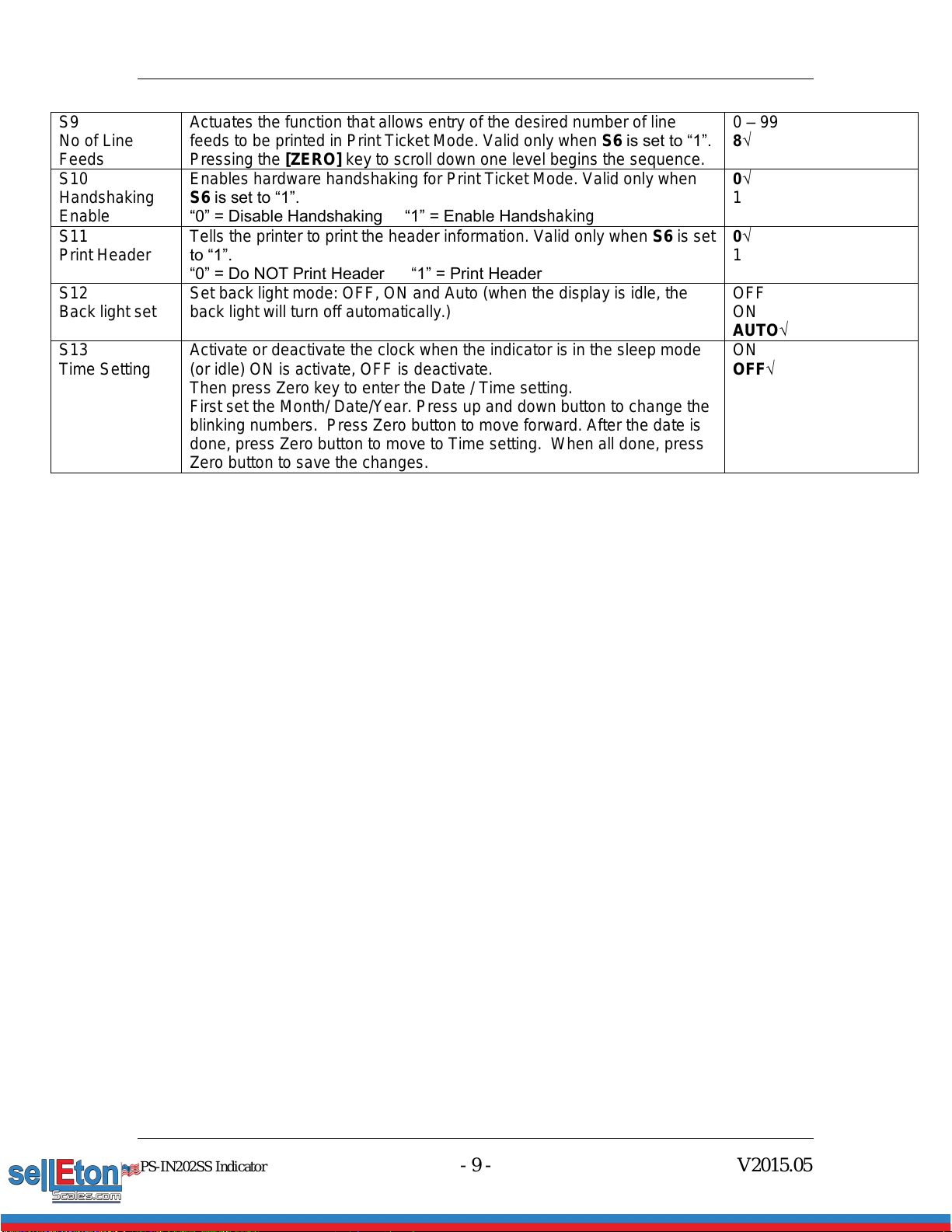
S9
No of Line
Feeds
Actuates the function that allows entry of the desired number of line
feeds to be printed in Print Ticket Mode. Valid only when S6 is set to “1”.
Pressing the [ZERO] key to scroll down one level begins the sequence.
0 –99
8√
S10
Handshaking
Enable
Enables hardware handshaking for Print Ticket Mode. Valid only when
S6 is set to “1”.
“0” = Disable Handshaking “1” = Enable Handshaking
0√
1
S11
Print Header
Tells the printer to print the header information. Valid only when S6 is set
to “1”.
“0” = Do NOT Print Header “1” = Print Header
0√
1
S12
Back light set
Set back light mode: OFF, ON and Auto (when the display is idle, the
back light will turn off automatically.)
OFF
ON
AUTO√
S13
Time Setting
Activate or deactivate the clock when the indicator is in the sleep mode
(or idle) ON is activate, OFF is deactivate.
Then press Zero key to enter the Date / Time setting.
First set the Month/ Date/Year. Press up and down button to change the
blinking numbers. Press Zero button to move forward. After the date is
done, press Zero button to move to Time setting. When all done, press
Zero button to save the changes.
ON
OFF√

PS-IN202SS Indicator - 10 - V2015.05
Chapter 3
Calibration
The indicator is calibrated by following the procedures embedded in P11 (Zero) and P12
(Span) of the Setup Menu. Each procedure enters a value into the indicator's non-volatile
memory:
P11 is the zero value (deadweight)
P12 is the span value (test weight).
The minimum test weight that can be used is 1% of the full-scale capacity. After the two
calibration procedures are executed successfully, a record should be made of both
calibration values in the Calibration Table below using the P 18 View procedure. NOTE: This
chapter assumes that the indicator is in Setup (“P”) Menu mode.
Calibration Table
Indicator
Zero Calibration
Span Calibration
Serial Number
3.1 Zero Calibration
a. While in the Setup mode, scroll to "P 11", then scroll down once using the [ZERO] key to
enter the zero calibration menu. The display will momentarily show "C 0" followed by a value.
This value is the internal A/D count and is useful when trying to troubleshoot setup problems.
b. Ensure there are no test weights on the platform and press the [ZERO] key again to zero
out the displayed value.
c. Press the [NET/GROSS] key to save the zero point value. The display will show "End C0"
momentarily then revert back to P11. Proceed to the P12 span calibration to complete the
indicator calibration.
3.2 Span Calibration
a. While in the Setup mode, scroll to "P 12", then scroll down once using the [ZERO] key to
enter span calibration menu.
b. The display will momentarily show "C 1" for the span calibration, followed by a value
with one flashing digit. This value will be zero with the Decimal Point parameter as selected
in P10. Place the test weight on the weighing mechanism.
c. Use the four direction keys to adjust the displayed value to the actual test weight value.
Increment the flashing digit by pressing the [UNITS] key. Decrement the flashing digit by
pressing the [ZERO] key. Pressing the [PRINT] key or the [TARE] key will change the
position of the flashing digit.
d. After setting the exact value, press the [NET/GROSS] key to save the value.

PS-IN202SS Indicator - 11 - V2015.05
e. If the calibration was successful, the display will show "EndC1" momentarily, then go to
“C2”.
f. Repeat Steps b-e using different test weights then proceed to Step “C3”.
g. Repeat Steps b-e using different test weights. Proceed to P12.
h. If the calibration was not successful, one of the error messages below will appear. Take
the indicated action to correct the problem then perform a new calibration.
"Err0" - The calibration test weight or the adjusted keyed-in weight is larger than the
full capacity of the scale. Change the calibration test weight or check the input data.
"Err1" - The calibration test weight or the adjusted keyed-in weight is smaller than 1%
of the full capacity of the scale. Change the calibration test weight or check the input
data.
"Err2" - The internal resolution of the scale is not high enough to accept the calibration
value.
3.3 View calibration values
Note: The values displayed in this procedure are valid only after a successful calibration has
been performed using P11 and P12.
a. While in the Setup mode, scroll to "F 18", then scroll down once using the [ZERO] key to
enter view calibration menu.
b. The display will momentarily show "CAL 0" followed by a value. This value is the zero
calibration value and should be recorded in the table below. Press any key to continue.
c. The display will momentarily show "CAL 1" followed by another value. This value is the
span calibration value and should also be recorded in the table below. Press any key to
return to upper level (P13).
3.4 Key-in zero calibration value
Note: This procedure is intended for emergency use only in the case of non-volatile memory
loss. A valid zero calibration value, obtained from a successful P11 calibration procedure,
must be used.
a. While in the Setup mode, scroll to "P14" then scroll down once using the [ZERO] key.
b. The display will momentarily show "CAL 0", followed by a flashing zero. Use the four
direction keys (shown in FIG 1) to adjust the displayed value to the zero calibration value.
c. After setting the exact value, press the [NET/GROSS] key to save the value.
d. The display will show "E CAL 0" momentarily then revert back to P14.
3.5 Key-in span calibration value
Note: This procedure is intended for emergency use only in the case of non-volatile memory
loss. A valid span calibration value, obtained from a successful P12 calibration procedure,
must be used.
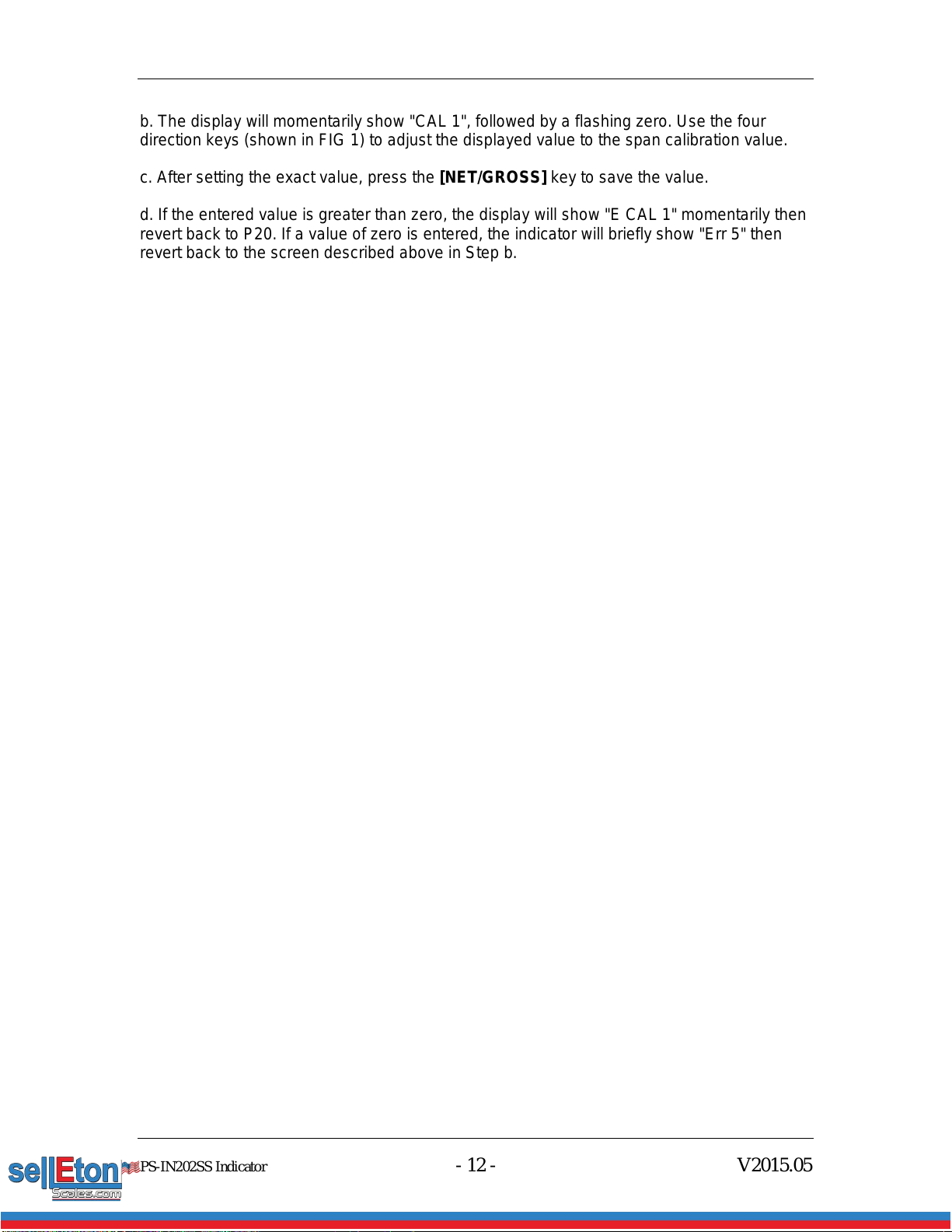
a. While in the Setup mode, scroll to "P15", then scroll down once using the [ZERO] key.
PS-IN202SS Indicator - 12 - V2015.05
b. The display will momentarily show "CAL 1", followed by a flashing zero. Use the four
direction keys (shown in FIG 1) to adjust the displayed value to the span calibration value.
c. After setting the exact value, press the [NET/GROSS] key to save the value.
d. If the entered value is greater than zero, the display will show "E CAL 1" momentarily then
revert back to P20. If a value of zero is entered, the indicator will briefly show "Err 5" then
revert back to the screen described above in Step b.

Version 2013.08
Chapter 4
Operation
4.1 Display
FIG 7
4.2 Display Details
LCD
Enunciator
LED Enunciator
Meaning
ZERO
Centre Zero enunciator. This light is illuminated
whenever the displayed weight is within ±0.25
divisions of true zero
N
NET
The indicator is displaying the net weight
G
GROSS
The indicator is displaying the gross weight
T
TARE
The tare weight has been established in the
system
lb/kg/oz/PCS
lb, kg, oz, PCS
Indicates the unit of the displayed weight. PCS =
pieces
STABLE
This light is illuminated whenever the scale is
stable
4.3 Keyboard
FIG 8
[ACCU] Accumulation function adding up the weights.
[UNITS] Toggles the indicator between the available weight units if enabled in the
User (“S”) menu. Available weight units are lb, oz and kg.
[ZERO] Sets the indicator to display zero provided the following conditions are met:

PS-IN202SS Indicator - 14 - V2015.05
a. The indicator is displaying Gross weight.
b. The displayed weight is within the zero reset range that is programmed in
P4 of the Setup (“P”) Menu.
c. The scale is not in motion or in overload.
[NET/GROSS] Toggles the indicator between Gross weight and Net weight only if a Tare
has been established.
[TARE] Used to establish a Tare provided the following conditions are met:
a. The indicator is not at or below Gross zero.
b. The scale is not in motion or overload.
[PRINT] Used to send weight information out to the serial port provided the scale is
not in motion or overload.
4.4 Weighing
a. Select the desired weighing unit by pressing the [UNITS] key until the desired unit is
indicated on the display.
b. If necessary, press the [ZERO] key to obtain a weight reading of zero.
c. Place the object to be weighed on the scale’s platter and allow the weight indication to
stabilize. If the item weight exceeds the scale’s weight capacity, it displays “❐❐❐❐❐❐”.
d. Read the weight shown on the display.
4.5 Tare Function
To weigh an item in a container, the weight of that container must first be subtracted from the
overall weight to obtain an accurate weight reading. This is known as taring.
a. Select the desired weighing unit by pressing the [UNITS] key until the desired unit is
indicated on the display.
b. If necessary, press the [ZERO] key to obtain a weight reading of zero.
c. Place the empty container on the scale’s platter and allow the weight indication to
stabilize.
d. Press the [TARE] key. The display shows zero weight and turns the NET indication on.
e. Place the material to be weighed in the container and allow the weight indication to
stabilize.
f. Read the weight shown on the display.
e. The display can be toggled between gross weight and net weight by pressing the
[NET/GROSS] key.
4.6 Counting Function
Please first make sure counting function is activated in parameter setting P17. If it is
activated, you can access counting by switching weighing units. When you see “PCS”, it is
in counting mode. It will start with sampling and you will see “5 –“ on the screen. Keep
pressing [UNITS] you will find the number changes to “10 –“, “20 – “…”100 -”. Place the
PS-IN202SS Indicator - 15 - V2015.05
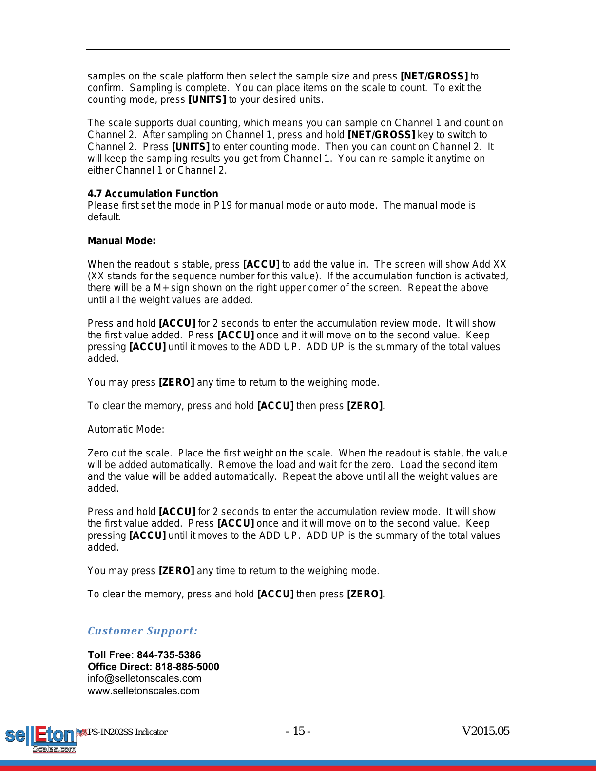
samples on the scale platform then select the sample size and press [NET/GROSS] to
confirm. Sampling is complete. You can place items on the scale to count. To exit the
counting mode, press [UNITS] to your desired units.
The scale supports dual counting, which means you can sample on Channel 1 and count on
Channel 2. After sampling on Channel 1, press and hold [NET/GROSS] key to switch to
Channel 2. Press [UNITS] to enter counting mode. Then you can count on Channel 2. It
will keep the sampling results you get from Channel 1. You can re-sample it anytime on
either Channel 1 or Channel 2.
4.7 Accumulation Function
Please first set the mode in P19 for manual mode or auto mode. The manual mode is
default.
Manual Mode:
When the readout is stable, press [ACCU] to add the value in. The screen will show Add XX
(XX stands for the sequence number for this value). If the accumulation function is activated,
there will be a M+ sign shown on the right upper corner of the screen. Repeat the above
until all the weight values are added.
Press and hold [ACCU] for 2 seconds to enter the accumulation review mode. It will show
the first value added. Press [ACCU] once and it will move on to the second value. Keep
pressing [ACCU] until it moves to the ADD UP. ADD UP is the summary of the total values
added.
You may press [ZERO] any time to return to the weighing mode.
To clear the memory, press and hold [ACCU] then press [ZERO].
Automatic Mode:
Zero out the scale. Place the first weight on the scale. When the readout is stable, the value
will be added automatically. Remove the load and wait for the zero. Load the second item
and the value will be added automatically. Repeat the above until all the weight values are
added.
Press and hold [ACCU] for 2 seconds to enter the accumulation review mode. It will show
the first value added. Press [ACCU] once and it will move on to the second value. Keep
pressing [ACCU] until it moves to the ADD UP. ADD UP is the summary of the total values
added.
You may press [ZERO] any time to return to the weighing mode.
To clear the memory, press and hold [ACCU] then press [ZERO].
Customer Support:
Toll Free: 844-735-5386
Office Direct: 818-885-5000
www.selletonscales.com

PS-IN202SS Indicator - 16 - V2015.05
Table of contents


