manuals.online logo
Brands
  1. Home
  2. •
  3. Brands
  4. •
  5. Panasonic
  6. •
  7. Accessories
  8. •
  9. Panasonic LS-H A Series User manual

Panasonic LS-H A Series User manual

CAUTIONS
3
This product has been designed to meet the specifications when it is used
along with the optional exclusive amplifier. If an amplifier other than the
exclusive amplifier is used, not only the specifications may not be met, but
it may also be a cause for malfunction or break down. Hence, please
ensure to use this product along with the optional exclusive amplifier.
●
●
●
●
●
●
●
●
●
●
●
●
●
●
●
This product has been developed / produced for industrial use only.
Always use the sensor with the connector to be joined to the amplifier.
Make sure that the power is off while wiring to the amplifier.
In case noise generating equipment (switching regulator, inverter motor
etc.) is used in the vicinity of this product, connect the frame ground
(F.G.) terminal of the equipment to an actual ground.
If power is supplied from a commercial switching regulator, ensure that
the frame ground (F.G.) terminal of the power supply is connected to an
actual ground.
Do not use the sensor during the initial transient time (0.5 sec.) just after
the power supply is switched on.
Do not run the wires together with high-voltage lines or power lines or put
them in the same raceway. This can cause malfunction due to induction.
Take care that the sensor head is not directly exposed to fluorescent
lamp from a rapid-starter lamp or a high frequency lighting device, as it
may affect the sensing performance.
The sensor head cable cannot be extended.
Make sure that stress is not applied directly to the sensor head cable
joint.
This sensor is suitable for indoor use only.
Do not allow any water, oil fingerprints, etc., which may refract light, or
dust, dirt, etc., which may block light, to stick to the emitting / receiving
surfaces of the sensor head. In case they are present, wipe them with a
clean, soft cloth or lens paper.
Do not use the sensor in vaporous, dusty or corrosive gas atmospheres.
Take care that the sensor does not come in contact with water, oil,
grease or organic solvents, such as, thinner, etc.
Make sure that the power is off while cleaning the emitting / receiving
windows of the sensor head.
SPECIFICATIONS
2
Notes: 1)
2)
3)
The model No. with suffix '-C5' stands for the 5m cable length type.
(e.g.) LS-H91A-C5
The model No. of retroreflective type sensor with the suffix '-Y' is the sensor without the RF-330
reflector. Arrange the reflector separately.
(e.g.) LS-H91-A-Y
Configure the mode settings in the applicable amplifier LS-400 series.
Diffuse reflective type
30 to 150mm
30 to 150mm
30 to 250mm
30 to 500mm
LS-H21-A
Connector for amplifier: 1 pc.
Warning label: 1 pc. (Chinese)
Type Coaxial retroreflective type
Sensing
range
(Note 3)
0.1 to 1mH-SP mode
0.1 to 1mFAST mode
0.1 to 3mSTD mode
0.1 to 5mU-LG mode
LS-400 seriesApplicable amplifier
Model No. (Note 1)
Item LS-H91-A (Note 2)
Connector for amplifier: 1 pc.
RF-330 (Reflector): 1 pc.
Warning label: 1 pc. (Chinese)
Accessories
30g approx.Weight
0.1mm2shielded cable, 2m longCable
Enclosure: PBT (Attachment: PEI), Lens cover: AcrylicMaterial
Red semiconductor laser Class 1 (IEC / JIS / GB standard)
(Max. output: 1mW or less, Peak emission wavelength: 655nm)
Emitting element
-10 to +55℃(No dew condensation or icing allowed), Storage: -20 to +70℃
35~85% RH, Storage: 35~85% RH
Ambient humidity
Ambient temperature
Green LED (Lights up when laser is emitted)Laser emission indicator
Orange LED (Lights up when amplifier output is ON)Operation indicator
●
●
●
●
Never use this product as a sensing device for personnel protection.
In case of using sensing devices for personnel protection, use
products which meet laws and standards, such as OSHA, ANSI or IEC
etc., for personnel protection applicable in each region or country.
Although this product corresponds to a Class 1 laser product, it is
dangerous to see the laser beam which has been passed through a
viewing optical system such as a lens etc. Hence, please avoid this.
Use of control or adjustment or performance of procedures
other than those specified in this instruction manual may
result in hazardous radiation expose.
WARNING
FOR SAFE USE OF A LASER PRODUCT
1
●
・
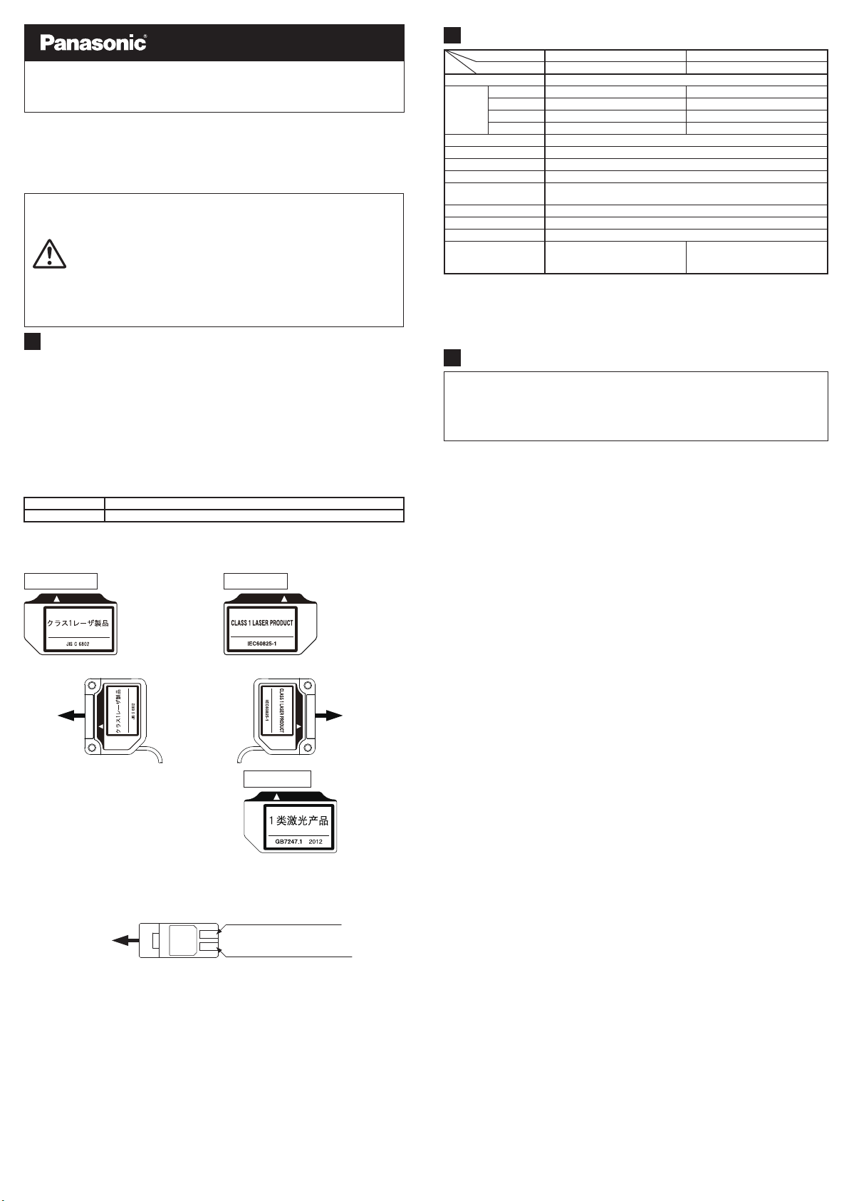
The following label is affixed on this product in accordance with the
Safety of laser product.
Warning label
<Label position>
In Japanese
(Based on JIS C 6802) In English (Based on IEC 60825-1)
LS-H□-A
Laser Sensor Head
INSTRUCTION MANUAL
MJE-LSHA No.0075-18V
●In order to prevent the accident by laser product and protect the users,
JIS C 6802-2014 “Safety of laser products” was established based on the
regulation of IEC (International electrotechnical Commission). This
regulation classifies laser products according to the level of hazard, and
provides the safety measures for respective classes.
This product are classified as “Class 1 laser products” according to
IEC 60825-1-2014 (JIS C 6802-2014) “Safety of laser products”.
●Laser hazardous class
Classification according to IEC 60825-1-2014 (JIS C 6802-2014)
Safe under reasonably foreseeable conditions of operationClass 1
Description of hazardous evaluationClass
・Laser emission indicator (green)
While laser is emitted, the laser emission indicator (green) of the sensor
head lights up.
This indicator is visible even when wearing laser protective glasses.
Operation indicator (Orange)
Laser emission indicator (Green)
Direction of
laser emission
In Chinese
(Based on GB 7247.1
-2012
)
●When this product is used in China,
affix the Chinese warning label (acces-
sory) on the label in the product.
Direction of
laser emission
Direction of
laser emission
Thank you very much for purchasing Panasonicproducts.
Read this Instruction Manual carefully and thoroughly for the correct and
optimum use of this product.
Kindly
keep this manual in a convenient place for quick reference.
PRINTED IN JAPAN © Panasonic Industrial Devices SUNX Co., Ltd. 2021
●When placing the sensor horizontally or vertically, the reflector must also
be positioned horizontally or vertically as shown in Fig. 1 below. If the
sensor is placed horizontally or vertically but the mirror is tilted as shown
in Fig. 2 below, the reflection amount will decrease, which may cause
unstable detection.
<Fig. 1 Proper positioning>
Mount the reflective mirror horizontally or vertically toward LS-H□-A.
<Fig. 2 Improper positioning>
The reflective mirror must not be tilt toward the LS-H□-A.
Good
Not good
MOUNTING
4
●The tightening torque should be 0.5N・
m or less. M3 (length 12 mm)
screw with washers
Sensor bracket
(optional)
SPOT-SIZE ADJUSTER (Only for LS-H21-A)
6
●The diffuse reflective type (LS-H21-A) incorporates the spot-size
adjuster to adjust the size of spot diameter.
DescriptionSpot-size adjuster
Turn the spot-size adjuster clockwise or counterclockwise to adjust the
spot diameter at your desired detecting distance.
However, if the adjuster is over turned, it may be damaged.
●
In principle, the coaxial retroreflective type (LS-H91-A) may be unable to
detect a mirror object or an object which easily diffuses the receiving light
at a short sensing distance since the polarized light becomes unstable.
In this case, take the following measures.
●The receiving light intensity may change depending on the surface
condition of the reflector. When a threshold value is set with the applica-
ble amplifier LS-400 series, sufficient margin should be taken into
account.
COAXIAL RETROREFLECTIVE TYPE
(Only for LS-H91-A)
5
・
・
・
Lower the sensitivity of M.G.S. function of the amplifier.
Change the response time.
Make the distance between the sensor head and the sensing object
farther.
<Measures>
WIRE CONNECTION
7
①Use a flat-head screwdriver (Blade width: 2mm or less) to
push the operating lever (white) located at the wire inlet
and remove the wire.
Releasing procedure
Blade width
2mm or less
●The cable of sensor head can be shortened to your desired length.
However, it cannot be extended.
<Connector for amplifier connection>
STRIP GAUGE
Strip gauge
Wire inlet
Operating lever (white)
1234
Wire inlet Releasing slot
Operating lever
(white)
④Place the head of a flathead
screw-driver underneath the
operating lever (white) through the
releasing slot, and lift the screw-
driver head.
If you hear a snap, the operating
lever (white) is returned and the
wire is fixed.
Wire connecting procedure
①Process the core length to 7 to 8 mm in accordance with 'STRIP
GAUGE' indicated on the side of this unit, and twist the core several
times.
When using shielded wires,
twist the wire until obtaining
the diameter of φ1.2 mm or
less.
STRIP GAUGE
Core length:
7 to 8 mm
Connector
for amplifier
Wire
②Use a flathead screwdriver (Blade
width: 2 mm or less) to push the
operating lever (white) located at
the operating area until it is
locked.
⑤Lightly pull the wire to ensure that
wire is not loose. When using
shielded wires, also check that
they do not contact each other.
③Insert the wire to the innermost of
the wire inlet.
Check that the shielded wire is
properly inserted into the wire inlet
as well as that the core end has
passed through the wire connection
area as shown in the right figure.
Operating
area
Flathead screwdriver
Blade width:
2mm or less
Cable color:
Black
Conductive core: Brown
Shielded wire
Cable color:
Gray
Conductive core: Yellow
Shielded wire
①
②
③
④
Terminal No.
Connecting cable
Operating lever
(white)
Releasing slot
Shielded wires
Wire
connection
area
Wire
inlet
Core end
Shielded
wire
INTENDED PRODUCTS FOR CE MARKING
8
●The models listed under 'SPECIFICATIONS' come with
CE Marking. As for all other models, please contact our office.
2

This manual suits for next models

2

Other Panasonic Accessories manuals

Panasonic MA3J1470G User manual

Panasonic

Panasonic MA3J1470G User manual

Panasonic ECONAVI CZ-CENSC1 User manual

Panasonic

Panasonic ECONAVI CZ-CENSC1 User manual

Panasonic AW-PB306 User manual

Panasonic

Panasonic AW-PB306 User manual

Panasonic MA3S132DG User manual

Panasonic

Panasonic MA3S132DG User manual

Panasonic HG-C1000L Series User manual

Panasonic

Panasonic HG-C1000L Series User manual

Panasonic AY-PB2002 User manual

Panasonic

Panasonic AY-PB2002 User manual

Panasonic KX-HNS107 User manual

Panasonic

Panasonic KX-HNS107 User manual

Panasonic MA24D52 User manual

Panasonic

Panasonic MA24D52 User manual

Panasonic MA3X788 (MA788) User manual

Panasonic

Panasonic MA3X788 (MA788) User manual

Panasonic KX-HNS105C User manual

Panasonic

Panasonic KX-HNS105C User manual

Panasonic Grid-EYE AMG88 Series User manual

Panasonic

Panasonic Grid-EYE AMG88 Series User manual

Panasonic KX-HNS107 User manual

Panasonic

Panasonic KX-HNS107 User manual

Panasonic Light Emitting Diodes LN217RPH User manual

Panasonic

Panasonic Light Emitting Diodes LN217RPH User manual

Panasonic MA3SE02 User manual

Panasonic

Panasonic MA3SE02 User manual

Panasonic MAS3795EG User manual

Panasonic

Panasonic MAS3795EG User manual

Panasonic D-IMager EKL3104 User manual

Panasonic

Panasonic D-IMager EKL3104 User manual

Panasonic HG-S Series User manual

Panasonic

Panasonic HG-S Series User manual

Panasonic MA2ZD14 User manual

Panasonic

Panasonic MA2ZD14 User manual

Panasonic MA6X124 (MA124) User manual

Panasonic

Panasonic MA6X124 (MA124) User manual

Panasonic MA4S111 User manual

Panasonic

Panasonic MA4S111 User manual

Panasonic MA3S133 (MA133) User manual

Panasonic

Panasonic MA3S133 (MA133) User manual

Panasonic HL-G1 Series User manual

Panasonic

Panasonic HL-G1 Series User manual

Panasonic GP-X SERIES User manual

Panasonic

Panasonic GP-X SERIES User manual

Panasonic WX-LA20 Guide

Panasonic

Panasonic WX-LA20 Guide

Popular Accessories manuals by other brands

GE Learn Mode Shock Sensor installation instructions

GE

GE Learn Mode Shock Sensor installation instructions

Omron B5W-LB21 Series user manual

Omron

Omron B5W-LB21 Series user manual

Honeywell QuadBand Triple IR FS24X Installation and operating manual

Honeywell

Honeywell QuadBand Triple IR FS24X Installation and operating manual

ULTIMATE SPEED UPK 10 C1 Operation and safety notes

ULTIMATE SPEED

ULTIMATE SPEED UPK 10 C1 Operation and safety notes

Salta EXCELLENT GROUND Assembly instructions

Salta

Salta EXCELLENT GROUND Assembly instructions

Joolz Geo3 Mono instruction manual

Joolz

Joolz Geo3 Mono instruction manual

Verilux CleanWave VH17 manual

Verilux

Verilux CleanWave VH17 manual

Craftsman 358.792442 instruction manual

Craftsman

Craftsman 358.792442 instruction manual

PASCO PS-3202 Replacement instructions

PASCO

PASCO PS-3202 Replacement instructions

SLOC SPR-203 Initial setup

SLOC

SLOC SPR-203 Initial setup

UniPi Technology IAQ RxW-THx quick start guide

UniPi Technology

UniPi Technology IAQ RxW-THx quick start guide

Buki BB Board Directions for use

Buki

Buki BB Board Directions for use

Balluff BTL7-V50D-M C003 Series Condensed guide

Balluff

Balluff BTL7-V50D-M C003 Series Condensed guide

Omron ZJ-SD Series user manual

Omron

Omron ZJ-SD Series user manual

Senect Oxygen Sensor O2S manual

Senect

Senect Oxygen Sensor O2S manual

Honeywell AURORA Installation instructions manual

Honeywell

Honeywell AURORA Installation instructions manual

VWR International 3025 Installation and operator's manual

VWR International

VWR International 3025 Installation and operator's manual

ASA Electronics versalogic VersaHIT Mono Manual instructions

ASA Electronics

ASA Electronics versalogic VersaHIT Mono Manual instructions

manuals.online logo
manuals.online logoBrands
  • About & Mission
  • Contact us
  • Privacy Policy
  • Terms and Conditions

Copyright 2025 Manuals.Online. All Rights Reserved.