SELMI TANK 200 Troubleshooting guide

A

B
C
PREFAZIONE
SELMI S.r.l. would like to thank you for purchasing our "TANK".
This manual is to be considered an integral part of the machine
and its purpose is to allow use of the machine throughout its
life, from delivery until demolition. Therefore, we suggest that
your read it carefully. Everyone working with the machine must
read this manual. It is also necessary to keep the manual in a
place accessible to operators at all times.
In the event of loss or damage of this manual, please ask
SELMI S.r.l. to send you a replacement copy.
The technical information contained in this manual belongs to
SELMI S.r.l. and must be considered proprietary.
The total or partial reproduction of the graphic design, text and
illustrations is forbidden
With a view to constant technical improvement, the company
reserves the right to make any necessary amendments to the
content of the manual, to the machine or to parts thereof.
Consequently, some of the illustrations may differ slightly from
your machine.
This document is an integral part of the “TANK”, as described in
section 1.7.4 of annex I of directive 2006/42/EC.
The Italian edition of this manual contains the original
instructions. The foreign language editions are to be considered
as translations of the original instructions.
© Copyright SELMI S.r.l.
Edition September 2019
EC DECLARATION OF CONFORMITY
The manufacturing company SELMI S.r.l., with main office in S. Vittoria D'Alba (CN) Italy – Via Statale, 151, in its capacity as manufacturer, declares, under its own
responsibility, that the machine named:
“TANK”
Serial number:
is compliant with all the provisions contained in the following directives: 2006/42/EC (machine directive), 2014/30/UE (electromagnetic compatibility) 2014/35/UE (low
voltage directive) and EC regulation 1935/2004 (contact with foodstuffs).
The norms adhered to that are used as a reference for the design, realization and testing of the machine are listed in the technical files archived at Selmi Srl.
The manufacturer also wishes to inform you that the technical file may, in the cases envisaged by the directive, be put together by the manufacturing company.
Year of construction:
Date: The liable person

TANK
0
1. General information 1
1.1. Structure of the manual 1
1.2. Messages Used 1
1.3. Aim and contents 1
1.4. Preservation of the manual 1
1.5. External components 2
1.6. Internal components 3
1.7. Details of the manufacturer 10
1.8. Identification plate of the machine 10
1.9. Identification plate of the CE marking 10
1.10. Inteded use 10
1.11. Operating environment 10
1.12. Noise level 10
1.13. Technical characteristics 9
1.14. Dimensions 9
1.15. Storage 12
1.16. Disposal 12
1.17. Warranty 12
1.18. person qualified to operate 13
2. Safety section 14
2.1. Safety information 14
2.2. Safety limitations 14
2.3. Safety symbols and plaques 15
2.4. Safety and protection devices 15
2.5. Client’s safety measures 17
2.6. Personal protection equipment 17
2.7. Residual risks 18
2.8. Applied Directives 19
2.9. Harmonized technical norms 19
3. Moving and transportation section 19
3.1. General norms 19
3.2. Packaging 19
3.3. Transportation 20
3.4. Removal of the packaging 20
4. Installation section 21
4.1. Positioning 22
4.2. Electrical connections 22
4.3. Installation of the machine 18
4.4. Commissioning 18
5. Operation section 22
5.1. Description of the controls 22
5.2. Functions of the buttons 22
5.3. Using the machine 22
5.4. Position of the user 22
6. Maintenance section 28
6.1. General information 30
6.2. General safety practice 30
6.3. Cleaning external parts
6.4. Emptying and cleaning the machine 48
7. Technical diagrams section 50
7.1. Electrical circuit diagram 50
7. Technical diagrams section 40

TANK
1
1. General information
1.1. Structure of the manual
To simplify t he reading and under standing of the
information contained in this manual and to make
searches quicker, it has been divided into sections, each
dedicated to a specific subject.
1.2. Messages used
Attention
This type of message is used to draw the reader’s
attention to more delicate or particular procedures
which, if not carried out correctly, may pose a risk
to the safety of the operator and cause damage to
parts of the machine.
Warning
This type of message is used to draw the reader’s
attention to procedures which, if not carried out
correctly or at pre-set intervals, may cause damage
to the machine or its parts, as well as to the product
being processed.
Environment
Messages relating to the environment draw the
operator’s attention to the rules to be followed to
prevent the risk of environmental damages
deriving, directly or indirectly, from use of the
machine.
Note
These messages highlight instructions, advice and
notes that can be particularly helpful during the
various uses of the machine.
1.3. Aim and contents
This manual has been drawn up in consideration of the
requirements of directive 2006/42/EC and paying
particular attention to describing all the procedures
necessary to obtain the best working conditions for the
machine and its operators, without neglecting product
quality:
The aim of this manual is, therefore, to provide the user
with all the information necessary for the correct use and
maintenance of the machine. Consequently it is absolutely
necessary:
- to meticulously follow the instructions given in the
manual during every phase of the machine’s life,
from transportation to demolition;
- for every machine operator to thoroughly read the
contents of this manual;
- for the company’s safety officer to make sure that all
machine operators have clearly understood how the
machine works
Attention
In case of doubts on the correct interpretation of
the instructions please contact the manufacturer to
obtain the necessary clarifications. All those
carrying out any kind of operation on the machine
must have thoroughly read and understood the
contents of this instruction manual.
Warning
If this manual is damaged or lost, please ask the
manufacturer or the authorised distributor in the
country where the machine is being used for
another copy.
1.4. Preservation of the manual
The instruction manual is an integral part of the machine
and must be used to train and inform professional figures
operating on the machine. Consequently, it is necessary to
follow certain simple instructions regarding its
preservation, as follows:
- store the manual in areas protected from humidity and
heat, so as not to jeopardise the quality or legibility of
any part of the publication;
- keep the manual is an easily accessible place known
to the machine operators;
- avoid handling the manual with dirty or greasy hands;
- if you think it is necessary to highlight important steps
of the manual, use non-permanent systems, to
preserve its legibility;
- do not remove, rip or rewrite any parts of the manual
for any reason.
TANK
2
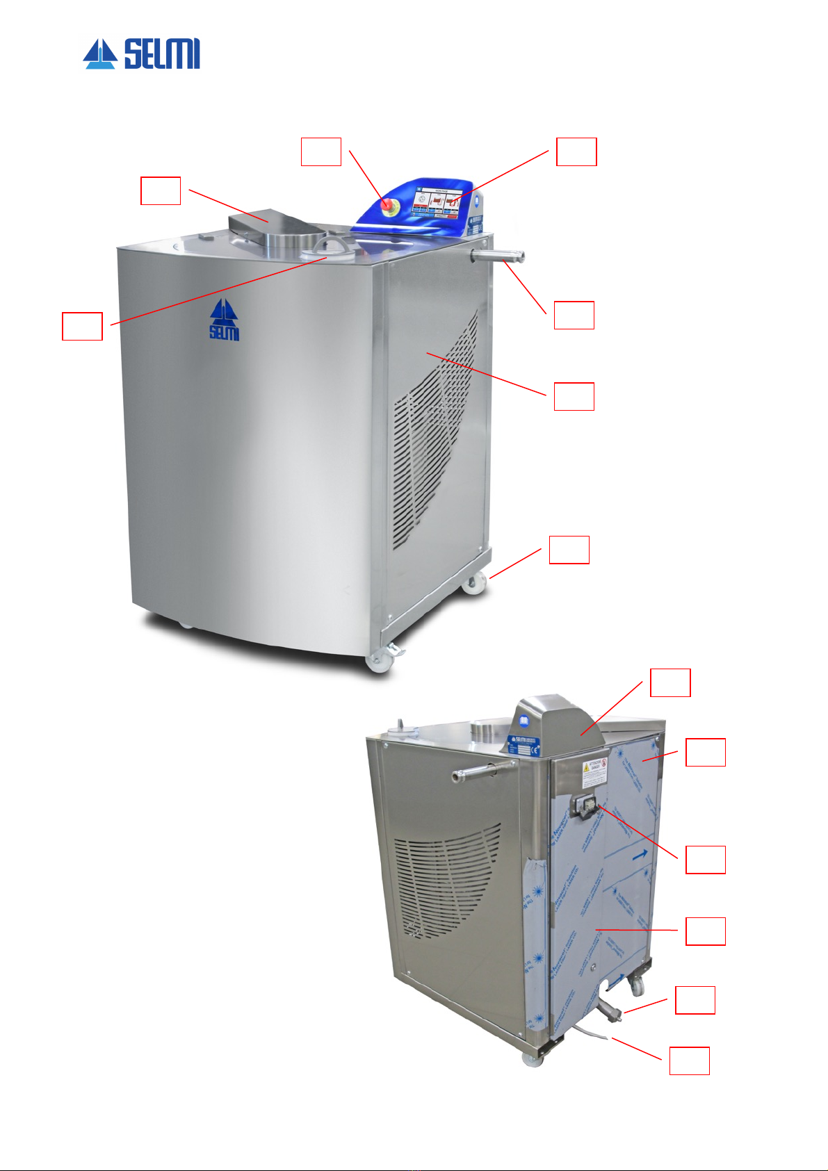
1.5. External Components
1. Touch screeen
2. Product exit point
3. Right protection panel
4. Sviwelling wheels
5. Handle fro the tank cover opening
6. Cover for the mixer transmission chain
7. Emergency button
8. Rear cover for the control panel
9. Rear protection panel
10. Pedal connection point
11. Electrical panel door
12. Unload/cleaning point
13. Electrical main connection cable
1
5
8
3
6
7
4
2
9
12
13
10
11
TANK
3
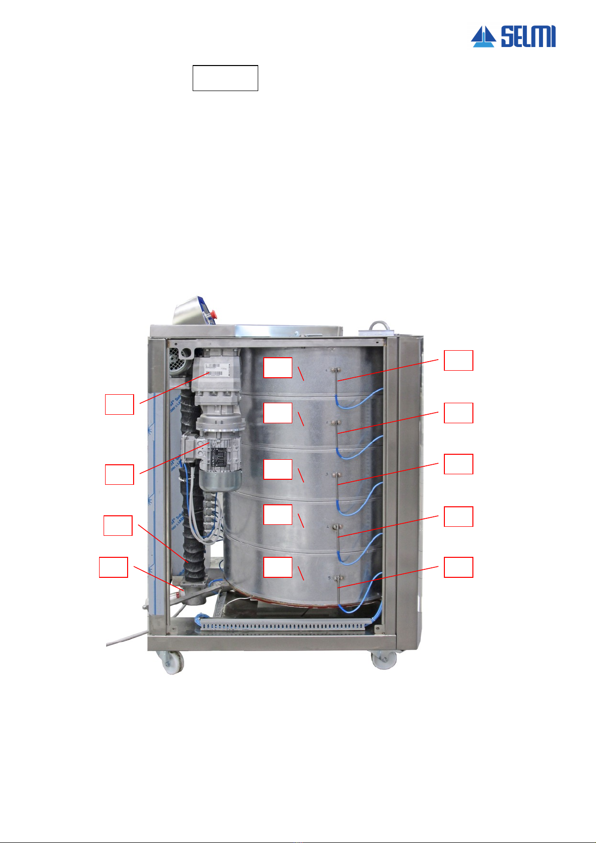
1.6. Internal Components TANK 400
1 - Mixer reducer
9 - Tank band resistance n°5
2 - Mixer motor
10 - Resistance temperature probe n° 1
3 - Column for product exit point
11 - Resistance temperature probe n° 2
4 - Unload / cleaning point
12 - Resistance temperature probe n° 3
5 - Tank band resistance n°1
13 - Resistance temperature probe n° 4
6 - Tank band resistance n°2
14 - Resistance temperature probe n° 5
7 - Tank band resistance n°3
8 - Tank band resistance n°4
10
5
2
3
4
11
12
13
14
6
7
8
9
1

4
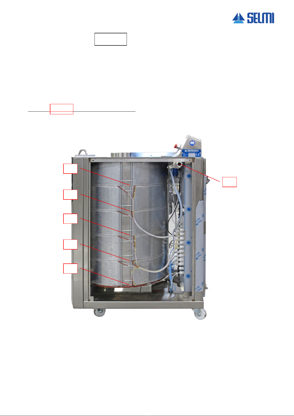
1.6. Internal Components TANK 200
1 - Mixer reducer
2 -Column for product exit point
3 - Mixer motor
4 - Unload / cleaning point
5 - Tank band resistance n°1
6 - Tank band resistance n°2
7 - Tank band resistance n°3
8 - Resistance temperature probe n° 1
9 - Resistance temperature probe n° 2
10 - Resistance temperature probe n° 3
8
5
3
9
10
6
7
1
2
4
TANK
5
1.6. Internal Components TANK 400
FOR THE TANK 200 ONLY 3 BAND RESISTANCES
1 - Tank band resistance n° 1
2 - Tank band resistance n° 2
3 - Tank band resistance n° 3
4 - Tank band resistance n° 4
5 - Tank band resistance n° 5
6 - Product exit point
1
2
3
4
5
6
6
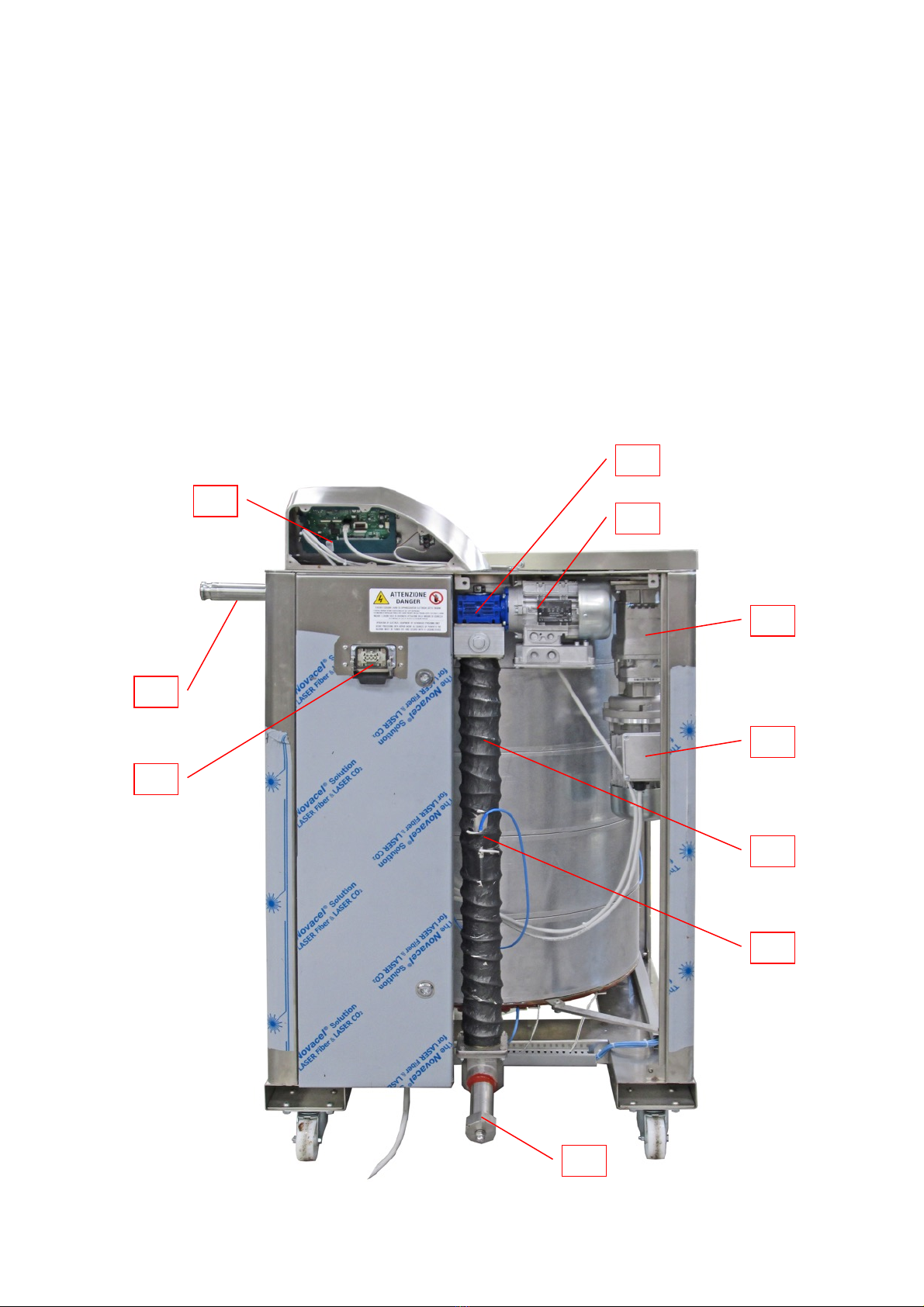
1.6. Internal Components
1. Toush screen
2. Product exit point
3. Pedal connection
4. Unload / cleaning point
5. Temperature probe for the column resistance
6. Column with resistance
7. Mixer motor
8. Mixer reducer
9. Product exit pump
10. Reducer
8
7
9
10
1
2
3
6
5
4
TANK
7
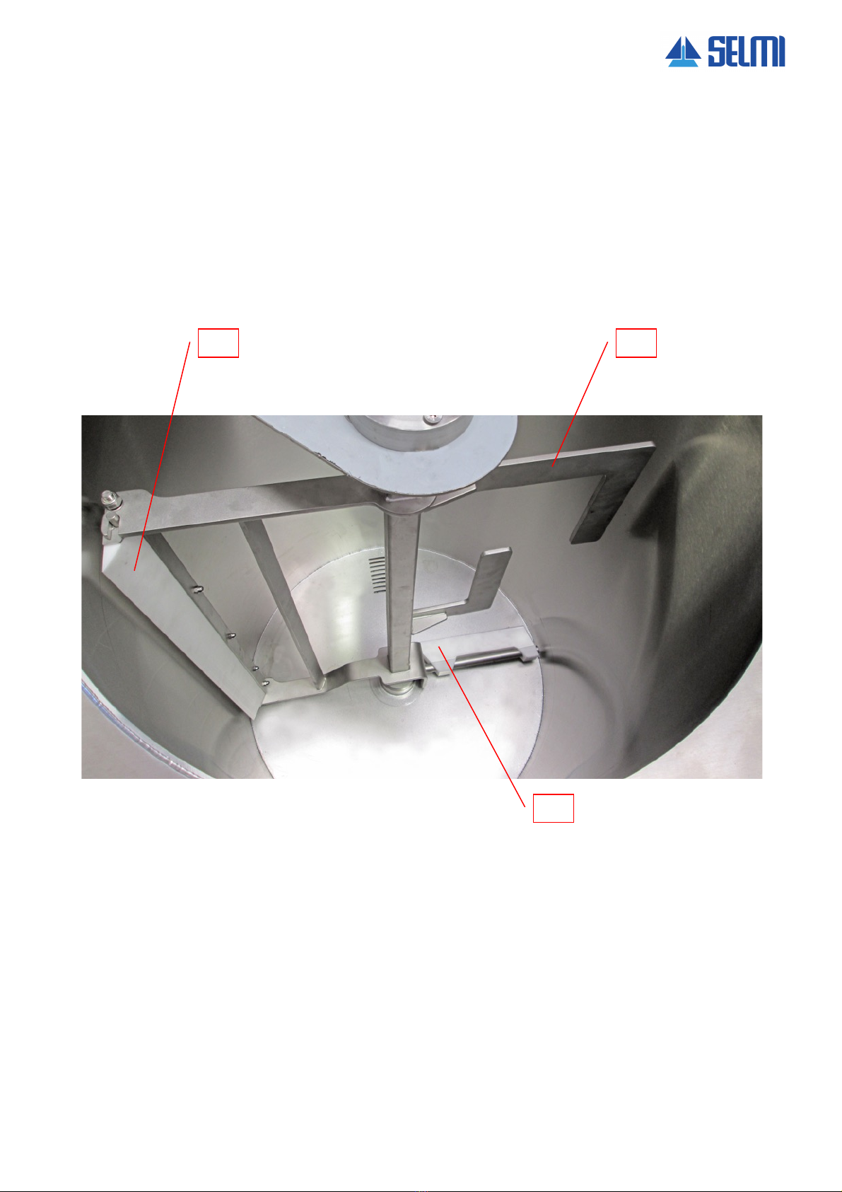
1.6. Internal Components
1. Mixer elements
2. Food grade plastic elements / scrapers for teh tank side
3. Food grade plastic elements / scrapers for teh tank bottom
1
2
3
8
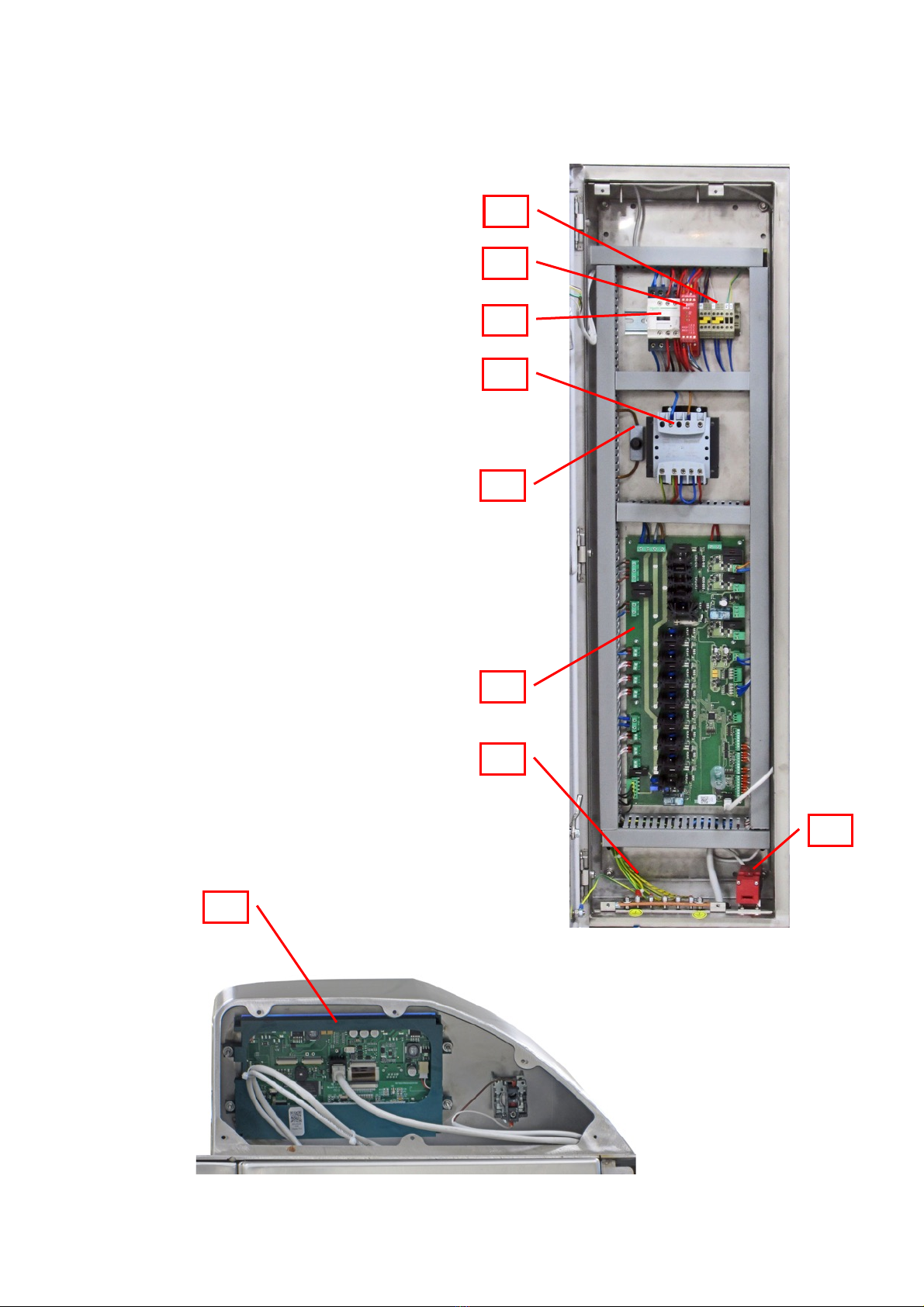
Electrical panel
1. Power board
2. Safety module
3. Main contactor
4. Transformer
5. Fuse holder
6. Power board
7. Ground connection
8. Micro security electrical panel door
9. Touch screen
9
1
5
4
3
2
6
7
8
TANK
9
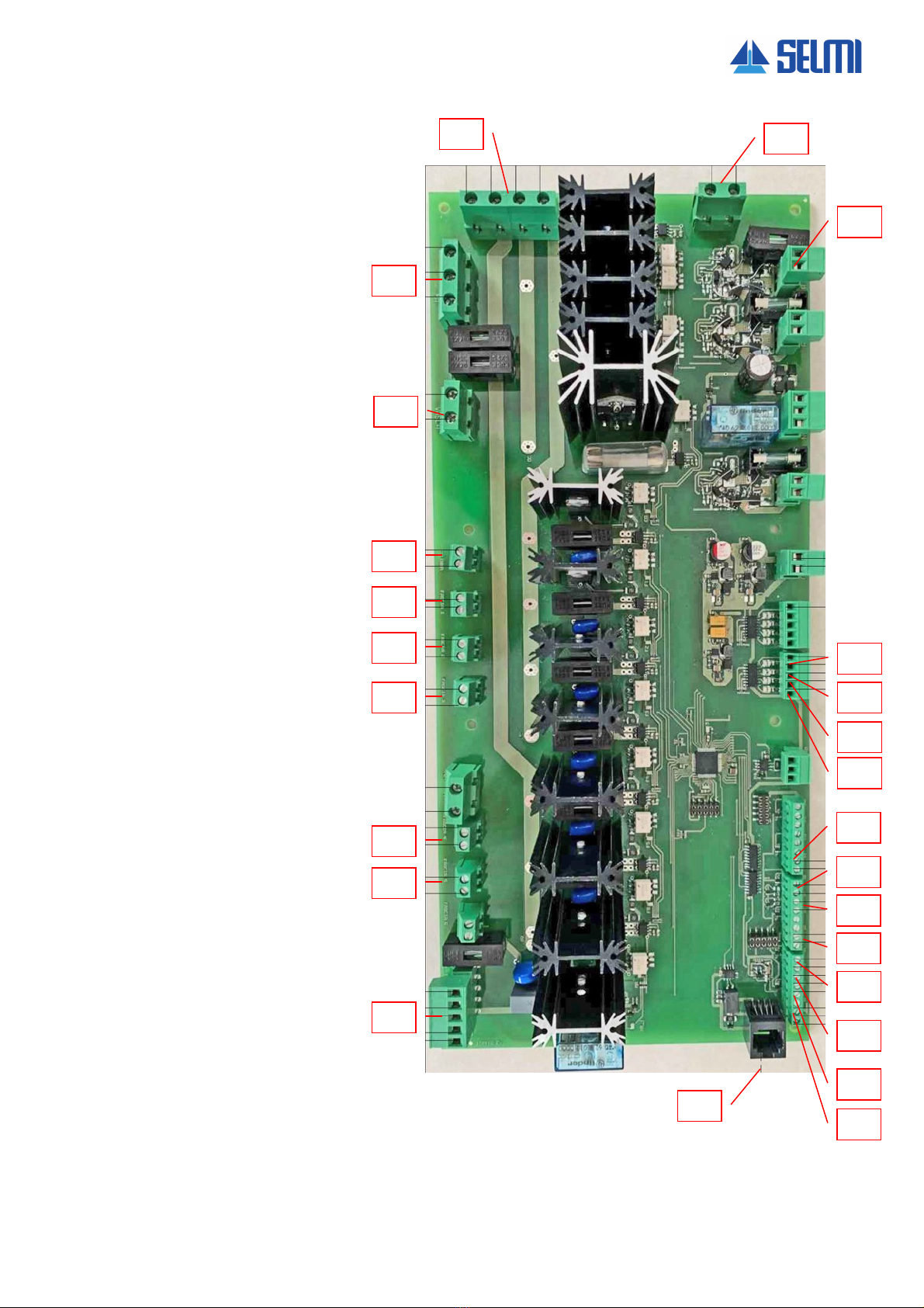
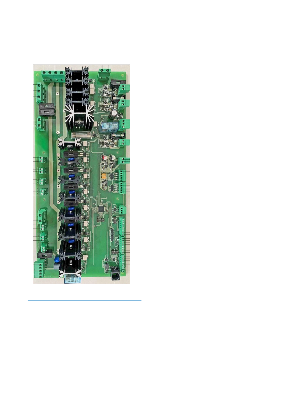
1.9. Power board
1 - Supply line 380V
2 - Mixer motor
3 - Tank bottom resisitance
4 - Column resistance
5 - Tank band resistance n° 1
6 - Tank band resistance n° 2
7 - Tank band resistance n° 3
8 -Tank band resistance n° 4
9 -Tank band resistance n° 5
10 - Pump motor
11 - Flat cable connection
12 - Probe n° 1
13 - Probe n° 2
14 - Probe n° 3
15 - Probe n° 4
16 - Probe n° 5
17 - Column probe
18 - Tank bottom probe
19 - Product exit probe
20 - Pedal
21 - Emerngency button
22 - Level sensor feed
23 - Safety level sensor
24 - Exit product pipe resistance
25 -Power board supply 24 ac
2
3
4
5
6
7
8
9
10
11
12
20
25
1
16
13
14
15
17
18
19
21
22
23
24
TANK
10
1.7. Details of the manufacturer
The machine described in this instruction manual was built
by:
SELMI S.r.l.
Via Statale, 151 – 12069 – S. Vittoria D’Alba (CN) Italia
Tel. 0172.479273 - 0172.479275 - Fax 0172.477814
www.selmi-group.it - info@selmi-group.it
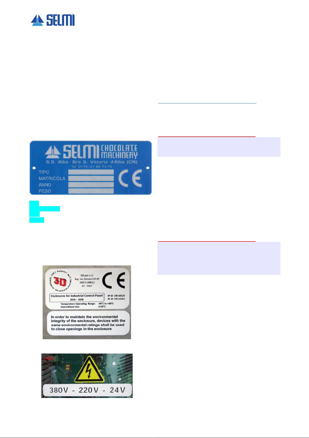
1.8. Identification plate of the machine (CE marketing)
There is a plate, similar to the one shown here, on the
machine, indicating details of the manufacturer, the CE
conformity mark and the machine’s serial number. Always
state this number when communicating with the
manufacturer.
Example of identification plate on the machine structure
TYPE
SERIAL NUMBER
YEAR
WEIGHT
1.9. Identification plate of the CE marking electric panel
(low voltage)
Example of identification plate on electrical panel. The correct
data shown in the section on the machine’s technical
specifications.
1.10. Inteded use
Chocolate mixers and melters TANK 400 Continuous
chocolate mixer and melter. Entirely built in stainless steel
AISI 304. The mixer can be operated in a continuous or
intermittent mode with programmable temperatures and
timed mixing. The heating of the tank and of the exit conduit
are separately thermoregulated. Integrated pump for the
supply of the relevant machines.
Warning
A use other than that specified is considered
improper. The machine is intended for professional
use only.
Attention
Do not place any small objects near the control panel
or the tank: they could fall and enter the tank, which
would contaminate the product.
1.11. Operating environment
To guarantee proper funct ioning the machine must be
protected from atmospheric agents. Its ambient operational
temperature should be between 15C° and 25C° with relative
humidity not exceeding 70%.
The working environment must be clean, sufficiently
illuminated and away from an explosive environment.
The environmental characteristics of the installation site are
specified in section 4.
Attention
The machine’s fixed guards have a variety of
openings to allow the internal units to cool. When the
machine is running, make sure that these openings
are not covered by cloths or objects that obstruct
proper air flow.
1.12. Noise level
The phonometric tests carried out on this specific machine
model show an acoustic pressure lower than 70 dB(A).
TANK
11
1.13 Electrical and tachnical charateristics
Total weight
300 kg
Total power installed
9 kW
Voltage
380 V
Phases
3
Frequency
50Hz or 60 Hz
Protection
IP 65
Tank capacity
200 or 350 kg
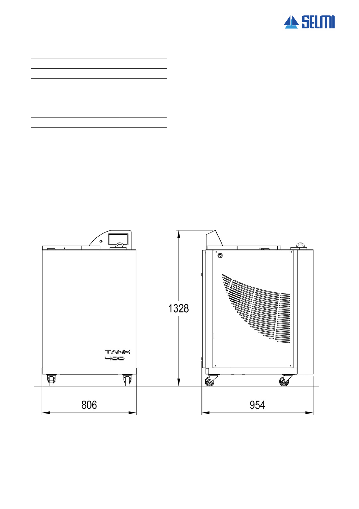
1.14 Dimensions
* This data may change according to the installation
conditions required under the contract. For the
correct data please refer to the label located inside
the electrical panel.

12
1.15. Storage
Remove the remaining product left in the machine
following the instructions in the appropriate section.
Stop the machine using the main switch and
disconnect it from the electricity main. Move it to a
spacious place (it is necessary to work all around the
machine).
Clean the tank, the removable components (i.e. screw
pump, mixer, nozzle) and the pipes as described in the
appropriate section.
Attention
It is absolutely necessary to follow the
instructions in order to insure the safety of the
operators and to avoid damaging the machine’s
removable parts.
Use a brush to cover the movable components and the
mechanical moving parts with a thin layer of food grade
lubricant. This can later be removed with an alkaline
de-greaser (Sodium Hydroxide) if the machine needs
to be re-installed.
Carry out the same operation on the machine surfaces,
taking care of avoiding the heating elements located in
the inner part of the machine.
Gather the parts (use as reference the delivery packing
list) and put them in the original packaging. Place
packets of hygroscopic salt based on silica gel in the
packaging.
Store all the parts in a sheltered place away from
atmospheric agents and in temperatures from 0° C to
40° C. Cover the parts with nylon in order to prevent
the accumulation of dust.
1.16. Disposal
Disposal will occur at the end of the working life of the
machine, which under normal conditions of use and
maintenance will be over ten years.
In the case of disposal all the components of the
machine will have to be disposed of in adequate waste
yards according to the legislation in force.
Before disposal it will be necessary to separate the
plastic or rubber parts and the electrical and electronic
material.
Environment
Parts made solely of plastic, aluminium and steel
can be recycled in the appropriate collection
centres.
According to the RoHS regulations electronic
boards and electric material should be recycled
separately in authorised collection centres.
1.17. Warranty
The manufacturer offers a warranty on this machine
model for a period of 24 months from the purchase
date, as shown on the fiscal document issued at the
time the machine is delivered.
The warranty will be void if the machine is repaired by
a third non authorized party or if fixtures and
accessories not supplied by or recommended or
approved by the manufacturer are used.
The warranty will also be void upon removal or
alteration of the plate showing the serial number and
other data.
Within the warranty period the manufacturer will repair
or replace, free of charge, parts that are faulty due to
manufacturing.
In case the repair has to take place at the
manufacturer’s site, the machine will have to be sent to
the manufacturer in its original packaging.
Transportation expenses will be covered by the
manufacturer during the warranty period.
The warranty does not cover the cleaning of the
functioning parts.
Defects not clearly attributed to the material or the
manufacturing will be examined. If the claim should
turn out to be unjustified all repair expenses, changed
parts and transportation will be charged to the buyer.
The warranty does not cover damage caused by the
following:
• accidental damage during transportation
• damage due to lack of care or procedures carried
out incorrectly
• damage due to improper use not conforming to the
warnings of the user and service manual
• components subject to wear and tear; a detailed list
is available in the components section.
Structural damage, modifications, improper alterations
or repairs can affect the functioning of the safety
mechanisms, thus making the declaration of conformity
and warranty void. Alterations on the machine can be
carried out solely by technicians authorised by the
manufacturer.

TANK
13
1.18. Professional personnel qualified to operate
the machine
The machine must only be used by authorized and
purposely trained personnel; the same precautions i s
also applicable to personnel who carry out
maintenance.
Personnel who do routine and extraordinary
maintenance must be specially trained professionals;
good knowledge of the machine is needed for
extraordinary maintenance.
Attention
Do not permit others to approach the machine
during its use or maintenance.
The following professional people, after having
received all the necessary instructions, are the only
ones allowed access to the machine:
Safety officer
The safety officer is responsible for protection and
prevention of risks in the workplace , as is mentioned in
European Directive 89/391/EEC (Safety in the
workplace), introduced in Italy with the 12/11/1994
Legislative Decree.
It is the responsibility of the safety officer to make sure
that all personnel who use/maintain the machine have
received all the instructions regarding their relative
roles contained in this manual.
Operator (user of the machine)
Operator trained and qualified for the use of the
machine (working cycle, potential adjustments, etc.).
He/she can only carry out the specific tasks described
in this manual reserved for this role.
Mechanical maintenance technician
The technician is qualified to use the machine as the
OPERATOR and furthermore to use it with the
protection disabled, to attend to the mechanical parts
for adjustments, maintenance and reparations.
He/she is not qualified to act on live electrical
installations.
The mechanical maintenance technician must have a
generic knowledge of the machine and a specific
knowledge on this machine model.
Electrical maintenance technician
The technician is qualified to use the machine as the
OPERATOR and furthermore to use it with the
protection disabled, to attend to the adjustments and
electrical installations for the purposes of maintenance
and repair.
If qualified, he/she may work when the electrical
panels, control devices, are live, provided he/she uses
appropriate personal protective devices.
The electrical maintenance technician must have a
generic understanding of the electrical panels and
specific knowledge on the electrical panel and
components of this machine.
Manufacturer
The manufacturer’s personnel are qualified to perform
all of the above-described operations.
Any operations not described in this manual may be
performed ONLY by personnel authorized by the
manufacturer.

14
2. Safety section
2.1. Safety information
Attention
The safety officer has the obligation to inform
the workers on the risks related to the use of the
machine.
Furthermore the employer must inform, educate
and train the user according to statutory laws.
The lack of compliance with the basic norms or
precautions could result in accidents during the
functioning, maintenance or reparations of the
machine. Accidents can often be avoided by
acknowledging potential hazardous situations before
they materialize. The operator must pay attention to the
potential dangers and have the training, the
competence and the necessary equipment to deal with
these tasks correctly.
The manufacturer cannot be held responsible for
accidents or damages resulting from the use of the
machine by personnel not adequately trained of having
used the machine improperly, as well as the lack of,
even partial, compliance to the safety norms and
interventions procedures contained in this manual.
The safety precautions and the warnings messages,
the operator could be subject to accidents with serious
consequences for himself and for other people.
In cases where tools, procedures, work methods or
working techniques not explicitly suggested by the
manufacturer are used, it will be necessary to make
sure that no dangers are present for the individual
carrying them out and to other alike.
Use exclusively original SELMI spare
parts. The manufacturer will take no
responsibility for accidents or damages in
the case o fuse of non-original spare parts.
If a tool not supplied by the manufacturer is installed on
the machine, the client needs to make sure that the
norms stated in Directive 2006/42/EC are adhered to. If
this new tool introduces new risks to the system then
the new system must be re-certified. In any case the
manufacturer cannot be held responsible for accidents
or damages caused by the machine if it has been
modified or equipped with non original accessories.
2.2. Safety limitations
Attention
The indications mentioned hereafter cannot
completely safeguard from all dangers that one
might encounter while using the machine; they
must be used in conjunction with common
sense and the experience of the operator, the
only indispensable measures for the prevention
of injury.
Every section has a list of specific safety measures for
different operations. The safety measures mentioned
here below are generic and should be followed for all
procedures on the machine.
The responsibilities assigned to specific people
concerning the use of the machine must be clearly
defined as stated in the “Qualified Personnel” section.
Attention
The use of the machine is forbidden to
personnel who have not been authorised or
trained by the safety officer.
Consult the manufacturer before carrying out
procedures that are not mentioned in this
manual.
Prolonged overloads or anomalies can cause the
electric motors and electrical appliances to overheat
with resultant harmful fumes. In such cases
immediately disconnect the machine from the mains
and do not approach the machine until such fumes
have been dispersed via adequate ventilation. In case
of fires do not use water jets on the machine – use
CO2 extinguishers instead.
The operator, any helping technician and the
maintenance technician must use the appropriate
personal protection equipment when working on the
machine.
It is forbidden to climb on the machine.
Do not touch the electrical wires, switches, buttons etc.
with wet hands.
The parts subject to wear and tear during the
functioning of the machine must be checked and
replaced as soon as they present noticeable signs of
wear and tear.
The manufacturer has designed and built the machine
to last for a reasonable time with the Client’s normal
conditions o fuse in mind; it is however necessary to
periodically check the components and the structure of
the machine, paying attention to any anomalous
conditions, such as, for example, cracks or
deformations. If necessary, contact the manufacturer to
ask for a complete check of the machine.
Please consult Section 4 (Installation) for the working
environmental conditions of the machine.
TANK
15
2.3. Safety symbols and plaques
The machine has a number of plaques with symbols
and/or safety messages stuck to it.
Attention
Make sure that all the safety messages are
legible and in good condition.
Replace the damaged plaques with the new ones from
the manufacturer. If a plaque happens to be on a part
that is being replaced, make sure that a plaque is
present on the new piece. For the cleaning of the
plaques consult the appropriate section (6.3).
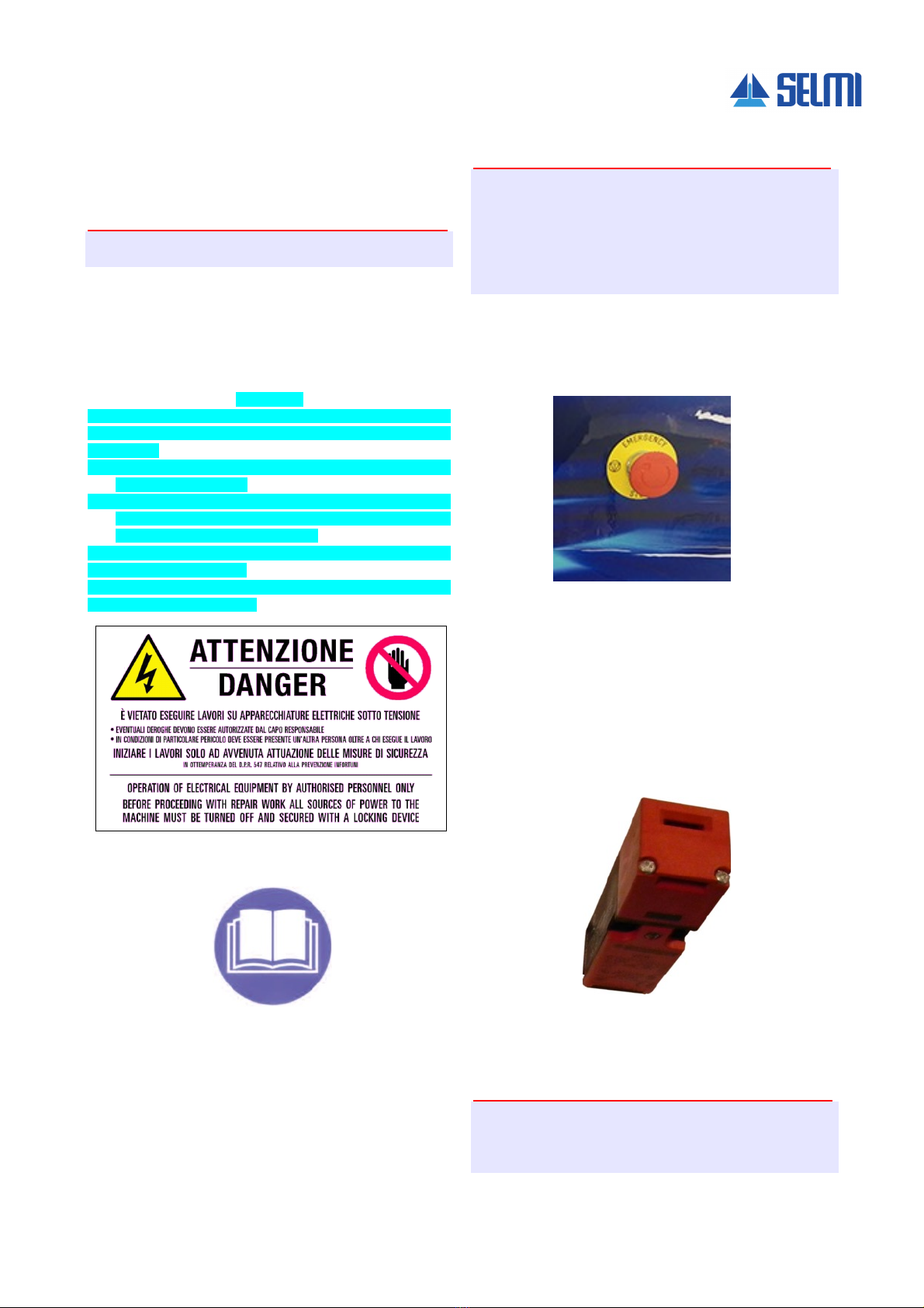
ATTENTIO N
THE PERFORMANCE OF WORK ON ELECTRICAL EQUIPMENT
CONNECTED TO THE POWER SUPPLY IS STRICTLY
FORBIDDEN
• ANY EXCEPTIONS MUST BE AUTHORISED BY THE
EXECUTIVE MANAGER
• IN PARTICULARLY DANGEROUS SITUATIONS, ANOTHER
PERSON MUST BE PRESENT IN ADDITION TO THE
PERSON PERFORMING THE WORK
WORK MAY ONLY BEGIN WHEN THE SAFETY MEASURES
HAVE BEEN IMPLEMENTED
IN OBSERVANCE OF PRESIDENTIAL DECREE 543 ON THE
PREVENTION OF ACCIDENTS
(positioned on the door of the electrical panel)
Label indicating compulsory reading of the manual
(positioned on the front of the machine)
2.4. Safety and protection devices
Attention
The components shown here are particularly
important for the safety of the operator and the
machine. In cases of malfunction or wear they
must be replaced with spare parts supplied or
authorized by the manufacturer.
While the machine is in use all the protection
devices must be correctly installed.
The safety devices present on the machine are:
• Mushroom emergency button with mechanical
unblock mechanism.
There is an emergency stop mushroom button on the
machine. Pushing it cuts voltage to all live parts by
means of appropriate devices. To reset it, release the
emergency button by turning its head and then push
the RESET button shown in the photo.
Before starting every shift, press it to make sure that it
works properly.
• Electric panel safety microswitch
Within the electrical panel there is a safety microswitch
which disconnects the voltage every time the panel is
opened for maintenance interventions.
Attention
Periodically check that the safety microswitch is
working properly.
If faulty, please proceed immediately with its
replacement.
16
• Fusibles
Warning
If fuses keep blowing it may be an indication of a
fault of the devices installed on the machine; in
such cases contact Technical Support.
This manual suits for next models
1
Table of contents
Other SELMI Commercial Food Equipment manuals

SELMI
SELMI ROASTER CENTOVENTI Troubleshooting guide

SELMI
SELMI COMFIT Troubleshooting guide

SELMI
SELMI RS250 Troubleshooting guide

SELMI
SELMI Macchia Troubleshooting guide

SELMI
SELMI Demoulding Troubleshooting guide

SELMI
SELMI CHOCOFORM Troubleshooting guide

SELMI
SELMI TOP EX Troubleshooting guide

SELMI
SELMI Filler Troubleshooting guide

SELMI
SELMI MICRON 25 Troubleshooting guide

SELMI
SELMI SPIDER Troubleshooting guide


