6AL3J11
GEN
INFO
1
2
3
4
5
6
7
8
9
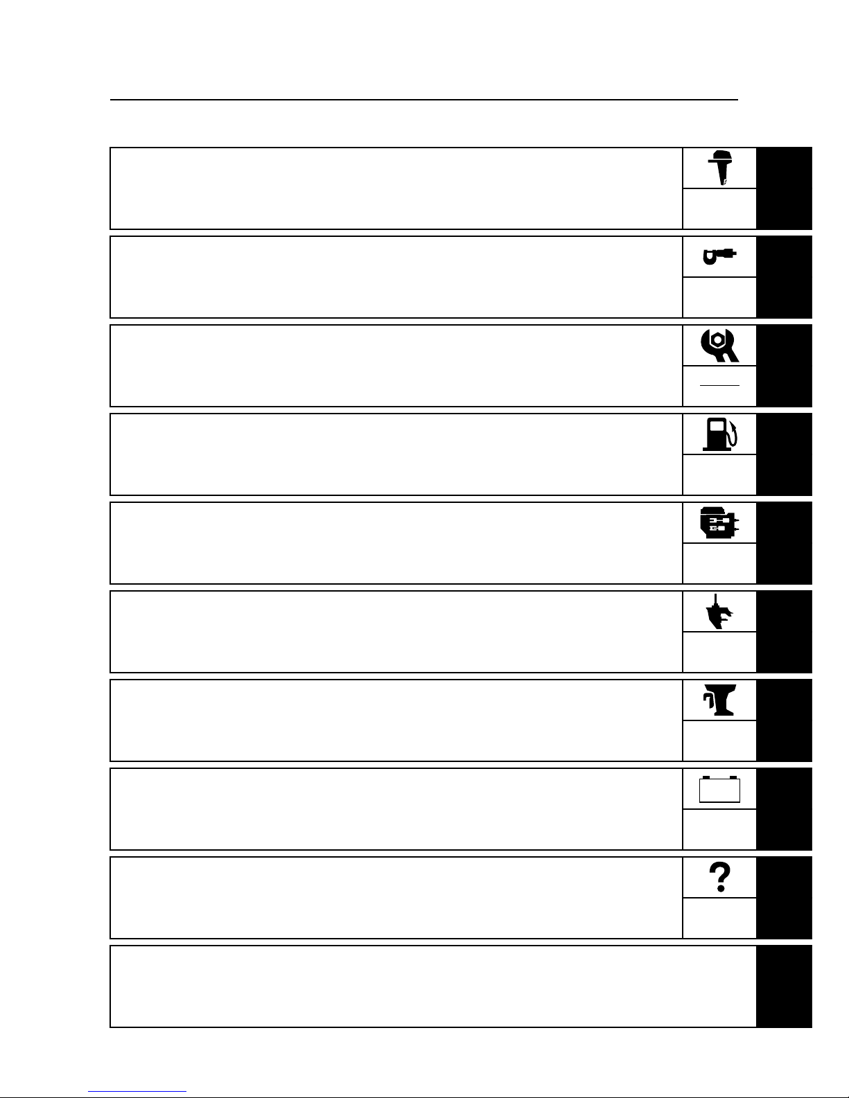
General information
How to use this manual.................................................................................1-1
Manual format............................................................................................1-1
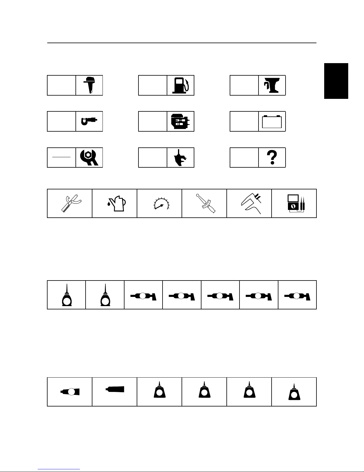
Symbol.......................................................................................................1-2
Abbreviation...............................................................................................1-3
Safety while working......................................................................................1-4
Fire prevention...........................................................................................1-4
Ventilation..................................................................................................1-4
Self-protection ...........................................................................................1-4
Part, lubricant, and sealant........................................................................1-4
Good working practice...............................................................................1-5
Disassembly and assembly.......................................................................1-5
Identification...................................................................................................1-6
Model.........................................................................................................1-6
Serial number............................................................................................1-6
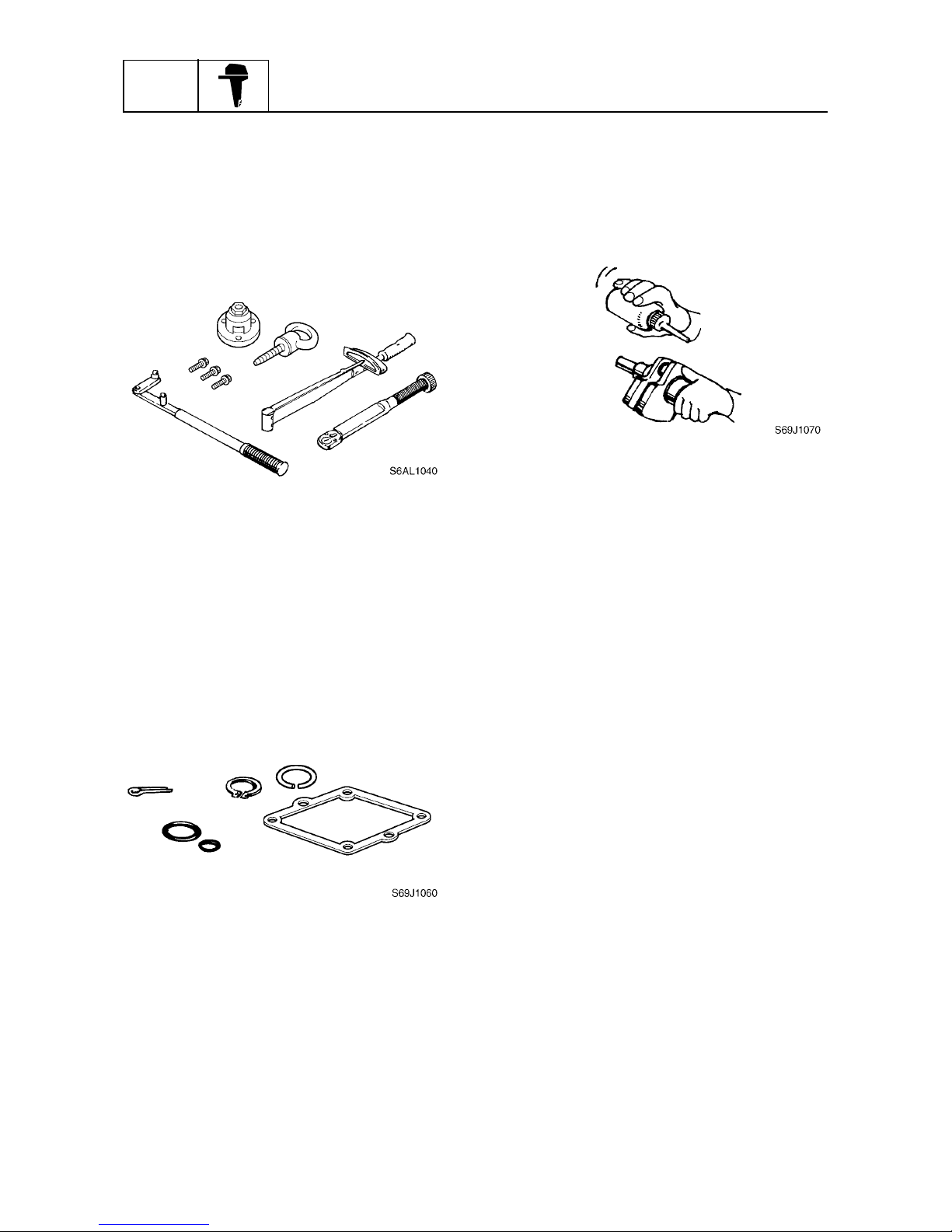
Special service tool .......................................................................................1-7
Feature and benefit......................................................................................1-14
Water separator.......................................................................................1-14
Injector.....................................................................................................1-15
ECM.........................................................................................................1-16
Propeller selection.......................................................................................1-21
Propeller size...........................................................................................1-21
Selection..................................................................................................1-21
Predelivery check ........................................................................................1-22
Checking the fuel system ........................................................................1-22
Checking the engine oil level...................................................................1-22
Checking the gear oil level ......................................................................1-22
Checking the battery................................................................................1-22
Checking the outboard motor mounting height........................................1-23
Checking the remote control cable..........................................................1-23
Checking the steering system .................................................................1-24
Checking the gear shift and throttle operation.........................................1-24
Checking the PTT system .......................................................................1-24
Checking the engine start switch and engine stop lanyard switch ..........1-24
Checking the cooling water pilot hole......................................................1-25
Test run ...................................................................................................1-25
Break-in...................................................................................................1-25
After test run............................................................................................1-25