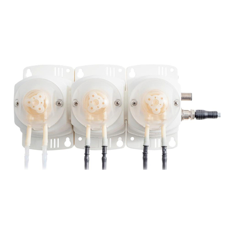
SELWOOD D75 User manual


Table of Contents
1Contact Details........................................................... 2
2Amendment Record................................................... 2
3Associated Documentation....................................... 2
4Glossary ..................................................................... 3
5Ordering Spares......................................................... 3
5.1 Body Unit Service Tool Kits.......................................... 3
5.2 Spares Kits .................................................................. 3
6Introduction................................................................ 4
6.1 Upon Receipt............................................................... 4
6.2 Scope .......................................................................... 4
6.3 Disclaimer.................................................................... 4
6.4 Conditions of Warranty................................................. 4
6.5 Conformity ................................................................... 4
6.6 Environmental Conformity............................................ 4
6.6.1 Spillages...................................................................... 4
6.7 Intended Use................................................................ 5
6.8 Foreseeable Misuse..................................................... 5
6.9 Manual Symbols .......................................................... 6
7Health & Safety........................................................... 7
7.1 Health & Safety at Work Act 1974................................ 7
7.2 Viton Material............................................................... 7
7.3 California (USA) Proposition 65 Warning Act................ 7
7.4 Workstation.................................................................. 7
7.5 Personal Protective Equipment (PPE).......................... 8
8Pump Components.................................................... 9
8.1 Component overview ................................................... 9
8.2 Separator System ...................................................... 10
8.3 Unique Selprime System............................................ 10
8.4 Non-return Valve (NRV)............................................. 11
8.5 Body Unit Label.......................................................... 11
9Performance............................................................. 11
10 Draining Body Unit Compartments......................... 12
10.1 Draining the Body Unit of Worked Fluid...................... 12
10.2 Draining the Body Unit of Oils .................................... 12
11 Lifting/Storage/Transportation................................ 13
11.1 Lifting......................................................................... 13
11.1.1 Pump Dimensions...................................................... 13
11.1.2 Recommended Lifting Technique............................... 14
11.2 Upon Receipt of the Body Unit................................... 15
11.3 Storage...................................................................... 15
11.4 Shelf Life.................................................................... 16
12 Installation and Commissioning ............................. 17
12.1 Pump Lubrication....................................................... 17
12.2 Commissioning Period............................................... 17
12.3 Post Commissioning Period....................................... 17
12.4 Installation Example................................................... 18
12.5 Maximum Allowable Flange Loads............................. 20
12.6 Pipelines.................................................................... 21
12.6.1 Pipeline Installation.................................................... 21
12.6.2 Suction Line................................................................21
12.6.3 Strainer.......................................................................22
12.7 Understanding the Pump’s Curve ...............................23
12.7.1 Pump’s Curve, Efficiency and BEP .............................23
12.8 Operating away from BEP .........................................23
12.8.1 The Correct Pump for the System...............................24
12.8.2 NPSH Explained.........................................................25
13 Body Unit Pre-operation...........................................26
14 Checks Whilst Operating .........................................27
14.2 Blockages...................................................................28
14.3 Running Dry ...............................................................29
15 Periodic Maintenance...............................................30
15.1 Serviceable Components............................................32
15.2 Fastening Torques......................................................33
16 Trouble Shooting......................................................34
16.1 Internal Component Recognition.................................34
16.2 Performance Drop......................................................34
16.3 Air Handling Performance & Lubricant Leaks or
Contamination................................................................................35
17 End of Life.................................................................37
18 Vacuum Test.............................................................38
19 Major Servicing.........................................................39
19.1 Servicing Prerequisites...............................................39
19.2 Air Pump Assembly....................................................40
19.2.1 Air Pump Suction Valve..............................................40
19.2.2 Air Pump Discharge Valve..........................................43
19.2.3 Neck Seal...................................................................44
19.2.4 Air Pump Drive Rod Assy & Bearing...........................45
19.2.5 Refitment of Air Pump.................................................48
19.3 Volute Removal & Refitting.........................................50
19.3.1 Removal.....................................................................50
19.3.2 Refitting of the Volute .................................................51
19.4 Wear Plates................................................................52
19.4.1 Rear Wear Plate.........................................................52
19.4.2 Fron Wear Plate .........................................................54
19.5 Impeller & Mechanical Seal ........................................55
19.5.1 Removal.....................................................................55
19.5.2 Fitment.......................................................................56
19.6 Impeller End Lip Seals................................................59
19.6.1 Remove of Lip seals...................................................59
19.7 Separator Assembly ...................................................61
19.7.1 Float...........................................................................61
19.7.2 Peel Valve..................................................................63
19.8 Delivery Valve Assembly ............................................67
20 Assembly Tools........................................................68
20.1 Tooling .......................................................................68
21 Declaration of Incorporation....................................69
22 Notes.........................................................................70

Page 2 of 70
1 Contact Details
Selwood Ltd
Bournemouth Road
Chandler’s Ford
Eastleigh
Hampshire
United Kingdom
Telephone contact: +44 (0) 23 8026 6311
Enquiries: info@selwood.co.uk
Website: www.selwood.co.uk
2 Amendment Record
Initial
Date
Action
ECN
Issue
SR
06/09/2023
Creation of Manual.
25927
A
Table 1: Amendment record, any changes to this manual must be recorded within table.
3 Associated Documentation
It is important that associated documentation is understood before using the pump, the latest issues can be found
on the Selwood website or by contacting a member of the Selwood team.
▪D75 Body Unit Parts List
▪Pump data sheets
▪Installation Drawing
Out of hours emergency service
(UK Pump Rental Breakdown & Equipment
Hire)
Monday to Friday: 5 pm to 8 am
Weekends and Bank Holidays: 24 hours
Tel: 03330 142 000

Page 3 of 70
4 Glossary
Term
Description
MSDS
Material safety data sheet
BU
Body unit
PPE
Personal protective equipment
NRV
Non-return valve
Running dry
The pump is running with no fluid moving through.
Head
The height in meters the unit will pump from the delivery valve when pumping clean water.
NPSH
Net positive suction head is a measurement of pressure in head on the suction side of the
pump, less the vapour pressure. This measurement is taken at the centre line of the
impeller.
RPM
Rotations per minute
dB
Decibel –a relative unit of measurement for sound.
SWL
Safe working load
ATEX
Atmospheres explosive: the risk of combustible gases within the ambient air.
Cavitation
A phenomenon where vapour bubbles form in a liquid when the pressure drops. Once the
pressure increases again, the bubbles collapse sending shock waves that may damage the
machinery or its components.
Driver
A power source that rotates the body unit shaft via a coupling. Internal combustion engines
or electrically powered motors are the most common.
C of G
Centre of gravity: this is a hypothetical centre point in a body of matter that dictates the
behaviour of the object, when acted upon by gravity.
IC engine
Internal combustion engine
NEMA
National Electrical Manufacturers Association
IEC
International Electro-technical Commission
Nominal
pressure (PN)
This specifies the maximum pressure a flange can withstand at a reference temperature of
20oC.
RPM
Revolutions per minute –the number of times the drive shaft completes a full revolution
within a minute.
5 Ordering Spares
Only the manufacturer’s or factory approved parts should be used when servicing the pump. It is advisable to hold
a small stock of spare parts to cover breakdown circumstance, these can be viewed in the body unit’s parts list
and purchased from Selwood’s sales team:
Telephone: +44 (0) 2380 250137
Enquiries: PumpSalesOffice@Selwood.co.uk
When ordering spare parts:
1. Always quote the pump serial number or machine serial number located on the plate fastened to the pump.
2. Always quote the ten-digit part number for the component, not the item reference number.
3. Always quote the description of the component.
5.1 Body Unit Service Tool Kits
For correct fitment of serviceable components, it is recommended to use special service tools. See servicing
sections for correct application of the tools and section 19.2 for a complete list.
5.2 Spares Kits
Visit the body unit’s parts list for spares kits that contain the necessary parts when performing a body of work.

Page 4 of 70
6 Introduction
Selwood has a full product range for all applications, including solids handling, high volume drainers, high head,
hydraulic submersible, chopper and positive displacement pumps. Please visit our website for a full range of
products.
Selwood products are extremely robust and reliable. Pumps are manufactured with quality, longevity and reliability
in mind to meet the needs of the most challenging environments. Accessible, removable and replaceable parts
allow easy maintenance, resulting in a longer life of the pump.
6.1 Upon Receipt
All Selwood products undergo a strict inspection process before leaving the workshop. Upon receipt of your
product, fully inspect the condition to ensure there has been no damage in transit.
6.2 Scope
This manual is for installing and maintaining Selwood’s D75 body unit only. This manual is written for units
received without a power source, which typically would be an IC (internal combustion) engine or an electrical
motor.
Procedures within this manual and associated literature must be carried out by a competent and trained person
only. Read and fully understand this manual before commencing the work.
6.3 Disclaimer
Although every effort has been put into the creation of this publication, Selwood cannot be held liable for any
injuries consequential of errors in this publication; Selwood’s manufactured products and associated parts are of
a hazardous nature.
This manual was originally written in English and should be referred to as the original source of information in the
event of any discrepancies between the original instruction and translated copies. Selwood reserves the right to
alter specifications and information given in this manual without prior notice.
The products of Selwood are designed, developed and produced in Selwood’s Chandler’s Ford facility. Many
features are covered by world-wide patents.
6.4 Conditions of Warranty
Selwood pumps are built for the rigours of rental and world-renowned for their quality, robustness and longevity.
Breakdowns are rare but if things do go wrong, we are committed to putting them right as quickly and efficiently
as possible.
If there are any issues regarding the pump’s warranty, refer to the website to complete a warranty form.
6.5 Conformity
This partly completed machinery must not be put into service until the final machinery or installation into which it
is to be incorporated has been declared in conformity with the provisions of Directive 2006/42/EC, where
appropriate.
6.6 Environmental Conformity
Oils, fuels and liquids captive to Selwood pumps may be hazardous to the environment and must be contained
and disposed of according to local laws. Failure to comply can incur substantial financial penalties, it is good
practice to:
▪Place the pump on a drip tray to further protect against fluids escaping the pump.
▪Constantly maintain all equipment and rectify any leaks immediately.
6.6.1 Spillages
Should a spillage occur, use absorbent material to clear the spillage as quickly as possible. Ideally use a dedicated
spillage kit to retain and remove such a spillage. Do not hose the area down or use any detergents and do not
allow the spilled liquid to enter drainage or water systems. Spillages must be reported to the local authorities.
Dispose of all absorbent materials in accordance with local laws.

Page 5 of 70
6.7 Intended Use
These highly efficient Selprime pumps are easy to couple, maintain and are highly robust. Perfect for use within
the following applications:
▪Clean water with fine solids
▪Screened sewage
Only operate the pump outdoors - modifying exhaust extraction for indoor use is not permitted.
The unit will be expected to operate continuously but be subject to general checks and maintenance as defined
within this manual.
6.8 Foreseeable Misuse
▪This pump is not suitable for explosive environments (ATEX) where fuels can be found in the ambient air. If
our pumps are used in explosive environments without the correct measures, the engine could overspeed or
cause an explosive hazard. However, parts are available as an option to minimise the risk of overspeed,
including engine overspeed shutdown valves and spark arrestors. Please contact your Selwood
representative.
▪Only deploy the pump on fluids within the pump’s capabilities. The pump’s specifications are listed within the
data sheets, located on our website.
▪Running the pump off curve can cause cavitation, bearing damage or recirculation of the flow. All of these
affect the pump’s efficiency and may lead to a premature breakdown.
▪Adhere to local environmental law when dealing with any liquid captive to the pump. Check the type of liquid
that the pump has been employed on before commencing the work, residues could be hazardous to health.
If in doubt, flush thoroughly with clean water before operation. Pumps deployed on sewage must be
thoroughly cleaned and sterilised after use.
▪Never run the pump against a closed valve, this does not include the body unit non-return valve (NRV).
▪Working with liquids exceeding 40 °C in temperature is not recommended as this may shorten the life of
internal components.
▪Liquid pressure may still be present even after shutdown of the pump. Attention should be paid to delivery
lines that are long or rise through any height, as these can contain large volumes of liquid. These lines must
be isolated and drained down before commencing work. Sudden release of this liquid can cause serious injury
to the operator; either directly or indirectly through the rotational motion it can induce.
▪Never insert anything into a running pump while the suction or delivery lines are disconnected.
▪Before starting any work, ensure the body unit is isolated from the electrical power supply either by the isolator
switch or, by disconnecting the pump at the battery and placing a sign in clear view: ‘DO NOT SWITCH ON,
MAINTENANCE IN PROGRESS!’. Selwood pumps have auto start facilities and may receive a start signal at
any time.
▪Operators must be skilled, competent and familiar with the product before use.

Page 6 of 70
6.9 Manual Symbols
Comply with literature.
Warning: hot surface with risk of burns.
Relevant information.
Warning: heavy loads. This symbol draws
attention to items or work which carry
higher risks of injury from lifting. Adhere to
local legislation involving lifting in these
instances.
Warning: personal injury.
Warning: explosive potential.
Warning: toxic exhaust gases.
Warning: environmental damage.
Warning: flammable substances.
Warning: corrosive substances.
Warning: risks from electricity that may
result in shock, burns or death.
Warning: To proceed with any work, the
pump must be disconnected from the
power supply. If an isolator switch is in use,
this must be locked in the closed position.

Page 7 of 70
7 Health & Safety
DANGER
Non-compliance with this section could result in injury or loss of life.
It is the responsibility of the employer to ensure correct PPE and safe working procedures are in place. Full PPE
is always recommended, and steel toe cap boots, eye protection (safety glasses), coveralls & high visibility vests
are essential. Certain tasks throughout this manual will reiterate additional items of PPE by attaching symbols
within Table 2.
7.1 Health & Safety at Work Act 1974
As manufacturers of pumps and associated equipment we wish to inform you that in compliance with section 6 of
the Health and Safety Act 1974, safety precautions should be taken when using our products.
Our aim is to ensure our products are safe and without risk to health when correctly used. Nevertheless,
appropriate health and safety precautions must be taken, and you are requested to have special regard to the
operational and safety requirements.
7.2 Viton Material
Components of this product may be fitted with seals or ‘O’-rings that are manufactured from Viton (synthetic rubber
and fluoropolymer elastomer) or similar materials.
Temperatures exceeding 400oC (720oF) produce a corrosive acid that cannot be removed from the skin. If signs
of material decomposition are evident, or if in doubt, wear chemical resistant gloves.
7.3 California (USA) Proposition 65 Warning Act
Diesel engine exhausts and some of its constitutes are known in the state of California to cause cancer, birth
defects and other reproductive harms.
7.4 Workstation
Where possible, carry out maintenance and servicing work in a clean workshop that considers all local safe
working procedure and local legislations. When work is to be carried out on site, it is essential that all onsite risk
assessments are filled out, and work is carried out in a clean and safe space.

Page 8 of 70
7.5 Personal Protective Equipment (PPE)
Ear Defence
Noise level at operator position is over
80 decibels when running, always
wear ear defence within the vicinity of
running pumps. Failure to comply
could result in hearing damage or
loss. Ear defence must be worn when
operating powered tools.
High Visibility Vest
Working around large machinery, vehicles
and moving plant can lead to crush and
traffic related injuries when people make
unintended contact with vehicles. High
visibility clothing improves visibility of
pedestrians and is essential.
Safety Footwear
Dropped objects including tools can
cause impact injuries, especially to
feet and toes. Working in certain
environments also introduces slip and
fall risks. Slip resistant safety footwear
with steel toe caps is essential.
Respiratory Protective Equipment (RPE)
Diesel exhaust fumes are hazardous to
health and can cause harm to the
respiratory system. Wear RPE when in
contact with diesel exhausts, paints,
solvents and other COSHH items that
contain hazardous air born chemicals
detrimental to human health.
Thick Disposable Gloves
Protection against cuts, skin
irritations, dermatitis and toxic or
corrosive substances captive to
Selwood pumps and substances
hazardous to health.
Protective Clothing
Full body protection from skin irritations,
dermatitis, and toxic or corrosive
substances. Ensure that coveralls are
clean before use.
Safety Glasses
Eyes must be protected from debris,
dust, smoke and corrosive chemicals.
Head Protection
To protect the head from falling objects or
striking against fixed objects.
Table 2: Health and safety symbols.

Page 9 of 70
8 Pump Components
8.1 Component overview
Figure 1: Body unit components. Direction of Rotation (DoR) indicated by white arrow.
Component
Description
Shaft end
The location where the driver is connected via a coupling; the coupling used is dependent on
the application and can be found in the pump’s parts list, if applicable. Contact Selwood for
further assistance.
Mechanical
seal
An almost perfect seal between the worked liquid and pump oils that allows a rotating
component and stationary component to operate together without overheating.
Impeller
Selwood’s D75 body units utilise the semi-open impeller which allows small solids to pass
freely between the curved vanes, whilst offering high efficiency capable of producing high
heads and flow.
Volute
The volute houses the impeller and assists with the flow of the liquid which is expelled through
the casing’s nozzle.
Separator
This controls the amount of air to liquid ratio within the pump and is explained later in this
chapter.
Delivery valve
Within is an NRV (non-return valve) in the form of a weighted flap or mechanical hinge, this
is detailed later in this chapter.
Air pump
Driven by the main pump shaft via a reciprocating drive rod, its task is to draw air from the
suction tube. This is detailed later within this chapter.
Suction tube
An intermediate component allowing the fitment of the separator and the connection of the
pipework.
Bearing
housing
As the name suggests, a housing to support the bearings, flushing chamber and associated
components, providing protection and a means to lubricate.
Table 3: Components relating to Figure 1
Air Pump
Delivery
Valve
Separator
Suction Tube
Bearing
Housing
Volute
Mechanical
Seal &
Impeller

Page 10 of 70
8.2 Separator System
Step
Stage
Image
1
The air pump drawers air from the suction
tube (white arrows).
2
The worked fluid displaces the removed air.
3
Rising water pushes the ball into the seat.
4
The ball is attached to a peel valve via a
connecting rod, which stops worked fluid
from passing the air pump (carryover). The
pump is now primed.
8.3 Unique Selprime System
Step
Stage
Image
1
Rotary motion from the engine/motor drives
the body unit main shaft.
2
Rotary motion is transformed to
reciprocating motion via the main shaft’s
eccentric and air pump connecting rod.
3
The actuator piston moves up and down
within the casting. A rubber seal encased in
the casting and secured to the actuator
peripherals creates the differences in
pressure (with assistance from 3 inlet/outlet
valves) needed to remove air from the
suction chamber.

Page 11 of 70
8.4 Non-return Valve (NRV)
The NRV can be found within the delivery chamber, although designs may slightly vary throughout the range, the
principles are the same. Suction lift can be affected by a dis-functional NRV, see servicing sections in this manual
to address.
Step
Stage
Image
1
Once the driver is running and the volute
is primed, liquid pressure builds.
2
The rise in pressure within the volute
causes the NRV to open.
3
Throughout operation the NRV will stay
open, providing the suction tube strainer
is fully submerged and there is no loss of
liquid pressure.
4
Once the driver ceases to run, liquid
pressure will decrease and the NRV will
close, stopping the worked liquid within
the pipework returning to the suction
side.
8.5 Body Unit Label
Each body unit is clearly identified with a body unit label such as
that depicted below. The location of the label may vary depending
on the body unit variant.
Term
Description
P/N
The top level 10-digit part number of the pump variant.
S/N
A unique number specific to each pump.
Year
The year of manufacture.
MAX RPM
The maximum running speed of the pump; this must not be exceeded.
Max pressure
The maximum pressure of the delivery in bar.
9 Performance
Specification
Value
Max speed
2000 rpm
Max head
23 m
self-priming lift
8.8 m
Max pressure
See body unit label
Max flow
See body unit label
Suction connection type
Solid spigot with 2.5 inch thread
Discharge connection type
Solid spigot with 2.5 inch thread
Max solid capacity
16 mm
Inspection
plate
Worked liquid
within the
volute
NRV

Page 12 of 70
10 Draining Body Unit Compartments
CAUTION
Oil Grade
Liquids captive to the pump can be damaging to the environment and must be disposed of in
accordance with local law. Drip trays are always recommended when operating & maintaining
Selwood pumps.
Failure to drain the body unit and delivery pipework in freezing conditions could result in damage
to the pump’s casting.
10.1 Draining the Body Unit of Worked Fluid
Step
Action
Image
1
Stop and isolate the body unit from its power supply.
2
Shut off the delivery and suction lines as close to the
body unit as possible.
3
Use a container to capture the escaping fluids from
all the drain points.
4
Release all drain valves to evacuate work liquid.
5
Close all drain taps once the pump is drained.
10.2 Draining the Body Unit of Oils
Step
Action
Image
1
Place a suitable container in position under the
respective drain plug (A, flushing chamber. B,
bearing housing).
2
Remove respective chamber filler cap (C, flushing
chamber. D, bearing housing), failure to do this may
create an air lock and stop the oil from draining.
3
Remove drain plug (A/B) respectively and allow the
oil to drain.
4
Closely inspect the oils for contamination or
miscolouring which may indicate faulty components,
please see troubleshooting sections for further
assistance. It may be necessary to flush the
chambers to remove all debris.
5
Once ready to refit drain plug, clean and apply
‘Loctite 572’or equivalent (pipe sealer).
A
B
D
C

Page 13 of 70
11 Lifting/Storage/Transportation
11.1 Lifting
CAUTION
Do not compromise safety when performing any manual lifting task. Selwood pumps are
designed so that manual lifting is to a minimum. However, where necessary, reference local
legislation and guidance. Any parts or assemblies with a notable mass are stated within the
servicing sections of this manual.
When lifting any Selwood products, refer to local legislation and guidance. If in doubt, contact
Selwood or a local lifting specialist. All lifting equipment including forklifts must be fully serviced
and inspected in accordance with local legislation.
11.1.1 Pump Dimensions
Note that dimensions are approximate. View the supplied installation drawing for exact dimensions.
Figure 2: Left, body unit top view and dimensions. Right, body unit side view and dimensions.
Length (mm)
Width (mm)
Height (mm)
Mass (Kg) -
no oil
571
358
490
84
Length
Width
Height

Page 14 of 70
11.1.2 Recommended Lifting Technique
CAUTION
Adhere to following guidelines when lifting the body unit:
▪Never in any circumstances allow personnel under suspended loads.
▪Ensure that lifting equipment can lift the gross weight of the pump.
▪Ensure all lifting equipment has been inspected and is compliant with local legislation.
▪Visually inspect lifting equipment for deformed material, corrosion, scoring & cracks. Check
components such as rivets, springs and latches are intact and functioning correctly. If
equipment is found to be defect, do not proceed with lift.
▪Ensure the correct PPE is worn in accordance with workshop/on-site regulations.
▪Pay attention to dimensions such as height, width, length, mass and C of G found within the
pump’s installation drawing.
Adhere to the following instructions when using strops to lift the body unit:
1. Three strops are required: two of equal length and one of sufficient length to secure the delivery valve neck.
2. Ensure lifting strops and corresponding body unit surfaces are dry so friction is increased.
3. Secure strops as seen in below image. Strop securing delivery valve neck must be taut to stop the unit
rotating.
4. Before committing to the lift, raise the unit slightly to ensure a level lift. If uneven, lower the unit and adjust
strops. Repeat until the unit lifts level.
Figure 3: Strop positions when lifting the body unit.

Page 15 of 70
11.2 Upon Receipt of the Body Unit
Although great care is taken to ensure the quality of our product, it is advisable to check the following upon receipt.
▪Check the body unit for any obvious physical damage to the castings and components.
▪Check all pipework between the air pump and separator is present and secure.
▪Check the delivery valve operates and correctly seats.
▪Check the oil levels as seen in section 13.
▪Follow section 0 to rotate the shaft, it is normal that the shaft is harder to rotate in certain positions due to the
eccentric.
11.3 Storage
When storing the body unit, adhere to the following:
▪Temperatures must be above -10°C and below +40°C. The relative humidity must be below 60%.
▪Do not store outside.
▪Protect the pump from mechanical shocks and vibrations, as this can cause brinelling (the permanent
indentation of a hard surface) to the components such as bearings. This may also cause damage to seal
faces.
▪Suction and discharge must be sealed to prevent dirt, debris and moisture build-ups. The body unit is supplied
with protective caps.
▪Bare shaft ends and any bare metal surfaces must be coated with an anti-corrosion treatment.
▪Secure shaft keys in place with a grip tie or similar.
▪To stop the build-up of dust and dirt, use a dust sheet. Do not use plastic coverings as this will create a build-
up of moisture underneath. If shrink wrap is used, cut holes to ventilate the product.
▪Do not store the unit on concrete flooring or directly on the ground, it must be stored on a wooden frame or
pallet, bolted in position with holes in the body unit feet and supported under the suction tube where necessary
to prevent the unit toppling over.

Page 16 of 70
11.4 Shelf Life
MUST READ
The body unit has a recommended storage limitation of two years before a service is necessary,
this is due to the internal parts life expectancy.
It is good practice to rotate the body unit’s drive shaft 4 ½ turns every two weeks to stop the seizure of internal
components. Proceed as follows:
1. Assemble a nut and bolt as specified in the below table (the amount of thread revealed must be a minimum
of the bolts diameter).
2. Coat the bolt threads with an anti-seize paste.
3. Tighten the bolt to the shaft thread until the nut bottoms out, then tighten the nut.
4. Rotate the shaft at least four and a half revolutions, ensure the shaft rests in a different position.
5. Loosen the nut and remove the bolt.
Figure 4: Left, shaft rotation. Right, nut attached to bolt with correct amount of thread revealed.
Body unit
Bolt size
D75
M10 X 1.5 - 6H

Page 17 of 70
12 Installation and Commissioning
CAUTION
Before commissioning the body unit for operation, completely read, understand and adhere to
section 6.7: ‘Foreseeable Misuse’.
If there is a risk of accidental contact by the operator, the exhaust system should be lagged or
screeded and the outlet directed away from the operator or nearby personnel. Engines should not
be run in hazardous explosive environments. All rotating parts that cause a hazard to the operator
or personnel must be guarded in accordance with local legislation.
The body unit is not supplied with control systems, electrical connections or an emergency stop,
this is the responsibility of the manufacturer when building the complete pumping unit in
accordance with local legislation.
Note that it is essential It is essential that earth terminals are connected to an earth point and care
should be taken to ensure that the correct sized conductors are selected to suit the current and
distance to be carried.
Noise emissions when this unit is installed to the driver:
▪The A-weighted emission sound pressure level, where this exceeds 70dB(A) at workstation.
▪The peak C weighted instantaneous sound pressure value, where this exceeds 63 Pa (130
dB in relation to 20 µPa) at workstation.
▪The A-weighted sound power level emitted by the machinery, where the A-weighted emission
sound pressure level at workstation exceeds 80 dB(A).
When these noise levels are required, the uncertainties surrounding these values shall be
specified.
The body unit does not require any utility e.g., electrical/water supplies.
When selecting a power source for the body unit, for example, an IC engine or electric motor, refer
to the body unit data sheet on the Selwood website and installation drawing supplied with the
pump. For further instruction, please contact your Selwood representative.
12.1 Pump Lubrication
It is most important to maintain the correct levels of oil in the flushing chamber and bearing housing (see section
13 for correct oil level), and to ensure that the oil is of the recommended quality and free from contamination.
Selwood recommend the use of the following products, which should be applied as per the following table. In
some territories, the following grades may be known under different trade names, please contact Selwood if
problems occur in identifying the correct product.
Component
Lubricant
Bearing housing
15W-40 oil
Flushing chamber
15W-40 oil
Actuator bore
Morris EP K2 grease
Impeller bore
Morris EP K2 grease
Paper gaskets
Morris EP K2 grease
Table 4: Body Unit lubrication.
12.2 Commissioning Period
Drain both pump chambers within 100 running hours of commissioning either a new or rebuilt pump and refill with
new oil. For the engine sump, refer to handbook.
12.3 Post Commissioning Period
If the pump is driven by a diesel engine, the oil in both pump chambers should be drained and renewed
simultaneously with the time schedule laid down by the engine manufacturer. This will usually require the oil to be
drained and replaced every 250 running hours. Under no circumstances should the period for the body unit exceed
500 running hours without oil being replaced in both chambers.

Page 18 of 70
12.4 Installation Example
If the body unit has been purchased as a single item, this section details some of the necessary installation
requirements when coupled with a motor/engine.
Step
Action
Image
1
The skid base is a standard part for supporting the
pump’s components, as well as absorbing and
dissipating vibrations & forces to the ground. The
base is necessary for securing the unit
components in position once aligned. Place the
base to firm level ground capable of supporting
the weight. Use anti-vibration (AV) mounts where
appropriate, these are required when coupling the
pump to an IC engine.
2
When installing a diesel engine, a flywheel
mounted coupling can be used. The coupling
must be selected with consideration to the engine
& body unit torque, speed and torsional
vibrations.
Couplings are selected for their
performance qualities unique to the
pump in hand, these are not
interchangeable between variants of
pumps. Doing so, will drastically shorten the life
of the pump.
3
Both the body unit and driver must be aligned on
two planes and rigidly mounted onto a chassis,
failure to do this will shorten the life of the
coupling. Refer to the fitment instructions supplied
with the selected coupling for further information.
AV mount
Skid base
Other manuals for D75
1
This manual suits for next models
2
Table of contents

