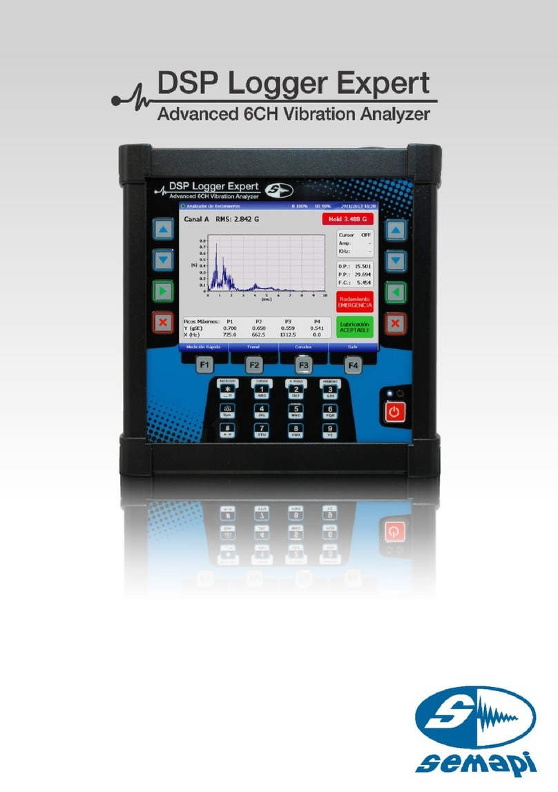
SEMAPI DSP Logger Expert User manual

User Manual
Measurer and Analyzer
Ver.: 2.0

Measurer and Analyzer
User Manual
User Manual • Version 2.0_2013
www.semapi.com
2
Measurer and Analyzer
Introduction:......................................................4
Quick Measurement:...........................................5
Bearing Analysis:............................................... 5
Spike Energy Level:........................................... 5
Home:............................................................... 6
Input parameters:.............................................. 7
Parameters copy:.............................................. 9
Class ISO10816:............................................... 9
Bearing Analyzer: ............................................ 10
Additional indicators:....................................... 13
Channel change:............................................. 14
Trend function:................................................ 14
Channel change:............................................. 15
Record:........................................................... 16
Return:............................................................ 16
Measurement Change:.................................... 16
Spike Energy Level:......................................... 17
Channel change:............................................. 20
Measurement change:..................................... 20
Standard table:................................................ 23
Additional indicators:....................................... 23
Channel change:............................................. 25
Trend function:................................................ 25
Channel change:............................................. 26
Record:........................................................... 27
Return:............................................................ 27
Measurement Change:.................................... 27
Function Dual Channel:.................................... 28
Dual channel:.................................................. 30
Record:........................................................... 31
Alerts of machine status: ................................. 32
Vibration analyzer: ............................................34
Input parameters:............................................ 34

Measurer and Analyzer
User Manual
User Manual • Version 2.0_2013
www.semapi.com
3
Preconfigured measurements:......................... 35
Acceleration:................................................... 36
Velocity:.......................................................... 36
Analyzer:......................................................... 38
Scalar measurements:..................................... 43
Multivariable:................................................... 45
Channel change:............................................. 45
Spectral measurements:.................................. 46
Spectrum / waveform:..................................... 49
Waveform Measurements:............................... 50
Channel change:............................................. 50
Dual channel measurements and triaxial:.......... 51
Channel change:............................................. 53
Triaxial measurements:.................................... 54
Channel change:............................................. 55
Instructions for use:......................................... 56
Troubleshooting: ..............................................57

Measurer and Analyzer
User Manual
User Manual • Version 2.0_2013
www.semapi.com
4
Introduction:
This module measures and analyzes mechanical
vibrations and variable AC and DC power. It groups
all the measurements of the DSP Logger Expert on
all its inputs, allowing the user to select vibration
measurements with pre-configured settings for
expert analysis or configurations designed to search
for other sources of or complex analyses of
vibrations.
The firmware contained in Option 1 of the DSP
Logger Expert is selected with the arrow keys or
directly with the 1 key.
Entering this firmware shows two options on the
screen, as shown in the following display.

Measurer and Analyzer
User Manual
User Manual • Version 2.0_2013
www.semapi.com
5
Quick Measurement:
This firmware contains 3 types of vibration analysis,
which are performed fully automatically.
It enables a simple load of the machine parameters
to be analyzed, allowing the system to capture,
analyze, and monitor vibration levels associated with
mechanical failures.
Bearing Analysis:
This tool defines an accurate calculation of the state
and condition of the bearing to test for bearing
and/or lubrication failure.
To do this, you must enter the estimated RPM of the
machine.
Spike Energy Level:
This tool defines an enveloping measurement value
of the Energy Spike ® analyzing bearing condition
and the values of bearing failure frequencies.
These calculations are performed automatically,
requiring the value of the estimated RPM, the model,
and the manufacturer of the bearing.

Measurer and Analyzer
User Manual
User Manual • Version 2.0_2013
www.semapi.com
6
ISO 10816 Measurements:
This measurement tool performs an analysis of
machine speed, adjusting the settings to the
requirements of ISO 10816 and evaluating the
condition of the states covered by the rule.
The input data that this tool requires involves the
classification of the machine in the norm groups.
In addition to the input of the RPM value, the meter
system expert shows vibrational levels for the
balancing, alignment, and rotation of the machine
backlash.
Home:
When entering the quick measurement by the icon
you will enter the settings window:

Measurer and Analyzer
User Manual
User Manual • Version 2.0_2013
www.semapi.com
7
Input parameters:
The parameter display indicates the status of the six
(6) inputs of the DSP Logger Expert according to the
connected and disconnected sensors.
The entries are grouped into 3 (three) groups for
Channel A and Channel B, each taking the X, Y, or Z
direction.
Red indicates no sensor signal.
Green confirms that the sensor and cable are in
good condition.
The parameter window displays all the fields
necessary for analysis calculations.
The only required field for the use of the tools is the
RPM.
The parameter window is divided into two (2)
segments. The left corresponds to Sensor 1, and
the right corresponds to Sensor 2.

Measurer and Analyzer
User Manual
User Manual • Version 2.0_2013
www.semapi.com
8
Code
Identification Number or TAG
Name
Machine Name
Point
Name or Nomenclature of the point
Obs.
Specific observations
RPM
The approx. revolutions of the point
Manufacturer
Bearing Mark of the point
Model
Bearing Model of the point
The input bearing manufacturer can be viewed by
selecting the list that has the system and factory
preloaded.
Model selection is performed via a selection of all the
bearings corresponding to the selected
manufacturer.
You can enter the bearing model by placing the first
number or the complete number of the bearing, so
the position will be close to or an accurate bearing.
Recommendation

Measurer and Analyzer
User Manual
User Manual • Version 2.0_2013
www.semapi.com
9
Parameters copy:
The parameter window contains a tool to copy the
parameters entered in sensor A or B.
The parameters that are not copied from one sensor
to the other bear manufacturer and model data.
When activated, the system will request the copy
from one sensor to the other.
Class ISO10816:
ISO class is selected depending on the measuring
machine.
Part 3: Industrial machines with nominal power
above 15 kW and speeds between 120 and 15000
RPM.
The criteria for the vibration of this standard apply to
a set of machines with a capacity exceeding 15 kW
and a speed between 120 RPM and 15,000 RPM.
The criteria are only applicable to vibrations
produced by the machine itself and not to vibrations
that are transmitted to the machine from external
sources. The effective value (RMS) vibration velocity
is used to determine the condition of the machine.

Measurer and Analyzer
User Manual
User Manual • Version 2.0_2013
www.semapi.com
10
Bearing Analyzer:
The first step is the entry of the parameters in sensor
1 and/or 2.
Once the parameters load, press F4 to activate
NEXT.
The menu functions F1 to F4 will change to the next
options.
Function F1 allows you to select analysis options.
This is done by pressing the F1
key until you reach the desired
option.

Measurer and Analyzer
User Manual
User Manual • Version 2.0_2013
www.semapi.com
11
Once there, confirm with the ENTER key.
Once confirmed, the measurement screen will be
presented online as measured from the first moment
of visualization.
The Bearing Analysis screen, shown above,
measures the input channel to the RMS value. The
red HOLD frame on the right keeps the maximum
value detected from the start of measurement or
since reset to zero using the #key.

Measurer and Analyzer
User Manual
User Manual • Version 2.0_2013
www.semapi.com
12
The spectral measurement corresponds to an
acceleration range of 800 lines with a maximum
frequency of 10 kHz.
On this configuration, the system calculates the
state of bearing and lubrication.
Each of these indicators shows a different status:
Bearing Lubrication
ACEPTABLE ACCEPTABLE
ACCEPTABLE CAUTION
CAUTION EMERGENCY
CHANGE
IMMEDIATE
The measurement is presented online.
To stop the measurement, press the
ESCAPE button.
To restart the measurement, press the
ENTER button.

Measurer and Analyzer
User Manual
User Manual • Version 2.0_2013
www.semapi.com
13
The status indicator measurement is at the top of
the screen, indicated by different colored circles.
In process measurement outside
Measurement stopped (flashing indicator)
Continuous measurement process
Additional indicators:
The following values are shown on the right side of
the screen:
0.P.: 0-Peak scalar value.
PP: Peak-Peak scalar value.
F.C.: Crest Factor scalar value.
Also shown are four (4) detected maximum peaks in
the spectrum, which indicate amplitude and
frequency.
The cursor function is activated with 1 key.
The indication appears for amplitude and frequency.

Measurer and Analyzer
User Manual
User Manual • Version 2.0_2013
www.semapi.com
14
Channel change:
Press F3 to change the channel.
This key will display the measurement of the
selected channel.
Another channel change option is to select the
function Overall Dual Channel (see pages 25 to 29)
Save data:
Press F4 to save measurement data.
Trend function:
The F2 key activates the screen that shows a trend
graph of the measurement on the selected channel.
The trend graph shows all measurements for a
maximum of 2 (two) minutes.

Measurer and Analyzer
User Manual
User Manual • Version 2.0_2013
www.semapi.com
15
The trend display shows the trend of the values
entered, with an up or down arrow coinciding with
the comparison of the last inserted value.
Declining value
Increasing value
Channel change: Press F3 to change the channel.

Measurer and Analyzer
User Manual
User Manual • Version 2.0_2013
www.semapi.com
16
Record: Using F2, you can save a time period of entered
measurements.
Once activated, start and end data recording by
pressing the F2 key again. Recording will also end
automatically when the set time of maximum
recording is completed.
Return: F4 will return spectrum measurements.
Measurement Change:
From the trend screen, you can directly access the
other tools by pressing F1.

Measurer and Analyzer
User Manual
User Manual • Version 2.0_2013
www.semapi.com
17
Spike Energy Level:
If the parameter data were pre-loaded for another
application, you can directly enter this function. If
not, you must complete the input parameter steps
(Pages 4, 5 and 6)
The tool screen shows the most relevant parameter
values of the measurement.
The main screen shows the value or level Energy ®
Spike with the color that corresponds to status of
the measurement.
Below the levels level status, data shows the
bearings, including the make and model.

Measurer and Analyzer
User Manual
User Manual • Version 2.0_2013
www.semapi.com
18
The graph shows the values and status of the fault
frequencies:
The bearings are composed of several clearly
differentiated components: inner race, balls or
rollers, cage, and outer race. The deterioration of
each of these elements will generate one or more
characteristic frequencies in the spectrums, allowing
for quick and easy identification. The four possible
frequencies of bearing damage are:
BPFO (Ball pass frequency of the outer race): The
physical number of balls or rollers that go through a
point outside the track each time the axis makes a
full rotation.
BPFI (Ball pass frequency of the inner race): The
physical number of balls or rollers that go through a
point inside track each time the axis makes a full
rotation.
BSF (Ball spin frequency):
The physical number of turns made by a ball bearing
each time the axis makes a full rotation.

Measurer and Analyzer
User Manual
User Manual • Version 2.0_2013
www.semapi.com
19
To view the envelope spectrum, press function key
F2.
In the spectrum envelope, the components can be
observed corresponding to bearing failure,
identifying the fault frequencies, and the values of
the peaks corresponding to each frequency.
It also shows the Energy ® Spike level with the color
that corresponds to status of the measurement.
Below the state with the SP level, bearings data is
shown, including make and model.

Measurer and Analyzer
User Manual
User Manual • Version 2.0_2013
www.semapi.com
20
Channel change:
Change the channel by pressing F3.
When activated, this key will display the
measurement of the selected channel.
To return to the screen bearing fault frequencies,
press function key F2.
Measurement change:
From the Trend screen you can directly access the
other tools by pressing F1.
Other manuals for DSP Logger Expert
1
Table of contents
Other SEMAPI Measuring Instrument manuals
