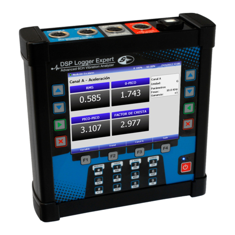
SEMAPI DSP Logger Expert User manual


User Manual
Hardware
Ver.: 2.0

Hardware
User Manual
User Manual • Version 2.0_2013
www.semapi.com
2
Hardware
Technical Specifications:......................................3
Important User Information:..................................6
Hardware DSP Logger Expert:..............................7
Introduction:...................................................... 7
Programs:......................................................... 8
Keyboard:......................................................... 9
Navigation keys:.............................................. 10
Main Keyboard:............................................... 10
Main keyboard with direct function:.................. 11
Battery charge:................................................ 11
Display Control:............................................... 13
Utilities:........................................................... 14
PC Connection:............................................... 15
Battery:........................................................... 16
Adjust Date/hour:............................................ 17
Display:........................................................... 18
Top connection panel:..................................... 19
USB:............................................................... 21
Input and sensor measurements:..................... 22
Accessories List:..............................................28
Troubleshooting: ..............................................29
Official certificate of guarantee............................30

Hardware
User Manual
User Manual • Version 2.0_2013
www.semapi.com
3
DSP Logger Expert
Technical Specifications:
Attributes DSP Logger Expert
Inputs Channels 6 (SIX)
Measurements from the inputs •Acceleration, velocity,
displacement from installed
sensors or portable monitoring
systems
• AC / DC sensors
• Pressure sensors
• Temperature sensors
• Measurements of entries from the
keyboard indicators or installed
instruments
• Input range, universal
tachometer: ± 25 V
• Visual inspections on the text
notes
Tachometer input • TTL/
analogous to ± 25V
• RPM range: 1-99.999
Input Overvoltage Protection Individual in all channels.
Measurement precision • 1%
Dynamic Range • To 95 db
Resolution • Programmable 400, 800, 1600,
3200, 6400, 12800, and 25600
lines
Measurement windows • Hanning
• Flat top
• Rectangular
Preprocessing • gSE and ESP (spike energy ®)
• Envelopment (demodulator) with

Hardware
User Manual
User Manual • Version 2.0_2013
www.semapi.com
4
four filters.
• Digital Integration:
Velocity and Displacement with
programmable high pass filters 1%,
5% and 10% of Fmax.
Filters, ESP • 1.25-2.5 kHz
• 2.5-5 kHz
• 5-10 kHz
Attributes DSP Logger Expert
Frequency response 0,2 a 20 kHz
Cutting low frequencies 0.18-100 Hz
Averages Programmable from 1-4096
peak hold, continuous
Cursors • Fixed and sweeping
• Simple + harmonics and dynamic
Trigger Modes • Trigger: External optical or laser
• Trigger Level: Fixed and
automatic
• Setting range and slope
Operative System Microsoft Windows CE
Processor 533 MHz, Samsung S3C2440A
DSP Analog Devices 2191MK
Communication USB, Wi-Fi
Internal Memory 128 MB
Additional Memory Micro SD 2GB
Weight 1450 grams
Enclosure IP65, Aluminum smelting
Display LCD, backlit color
• VGA (640 x 480)
• 5.7 inch
Visible area: 115.2 x 86.4 mm
Batteries Rechargeable lithium ion
Connectors Connector A and Connector B of
5-pins
AMPHENOL CONNECTOR
Connector C and Connector D
Auxiliaries
Input AC
Input DC
Tachometer
Battery Charger (by duplicate)

Hardware
User Manual
User Manual • Version 2.0_2013
www.semapi.com
5
Use caution with high acceleration, severe blows,
blows to the display, and cutting elements or tips.
High input voltage on the battery charger. It can
create a discharge of (100-240) V if the battery
charger makes contact with the plug.
Static charges can cause temporary changes in the
display or keyboard functions.
When making installations with extensive cables, use
extreme caution with all moving parts of the machine
and installation of the sensors.
The DSP Logger Expert can be operated in the rain
and supports significant water on the connectors
and keyboard. Grade: IP 65.
(Not suitable for submerging)

Hardware
User Manual
User Manual • Version 2.0_2013
www.semapi.com
6
Important User Information:
This solid conditions equipment has different
operating characteristics than electromechanical
equipment.
The safety standards are different from solid state
equipment and wired electromechanical devices.
Because of this difference, and also because of the
great variety of uses for solid conditions equipment,
all persons responsible for applying this equipment
must take all appropriate electrical safety measures
and study for impact damage.
SEMAPI will be responsible for indirect or
consequential damages resulting from the misuse of
this equipment.
The examples and diagrams in this manual are
included for illustrative purposes only.
No responsibility is assumed with respect to use of
the information, circuits, equipment, or software
described in this manual.
Throughout this manual we use notes to make you
aware of safety considerations when necessary.

Hardware
User Manual
User Manual • Version 2.0_2013
www.semapi.com
7
Hardware DSP Logger Expert:
Introduction:
The DSP Logger Expert is a vibration measurement
platform with 6 channel input accelerometer signals,
4 channels of AC, and 2 channels of DC.
It also has tachometer input for phase measurement
and headphone output.
The operating system runs on a platform with a 533
MHz microprocessor, Samsung S3C2440A
(Maximum 633 MHz), 64 MB RAM, and 2 GB flash
in its basic version (Expandable to 16 GB).
The signal processing is done on an Analog Devices
DSP 2191MK and 6 channel digital analog
converter, which allows simultaneous measurements
of 6 entries.
The equipment is turned on in full from the activation
of the power key. The operating system cannot be
suspended.
Turning on the equipment, with the operating
system load and main menu programs, take about
30 or 40 seconds.
Start is initialized when the blue LED on the front of
the equipment is turned on.
After initialization, the equipment’s first screen will
show icons for the measurement applications menu.

Hardware
User Manual
User Manual • Version 2.0_2013
www.semapi.com
8
Programs:
The DSP Logger Expert contains up to 6 (six)
different operating programs. These programs are
independent of each other and may restrict access,
depending on the version acquired.
Each of these programs can be updated without
having to physically open the equipment and can be
charged via a USB communication port.
Although these programs are independent each one
responds to the overall calibration of the equipment.
Any change in the calibration will affect all programs.
Once the DSP Logger Expert is initialized, it will
display a log-in screen and the programs contained
therein. Each program can be accessed by using
the navigation keys and can be confirmed by
pressing ENTER directly or by pressing the number
of the key program 2 (two) times.
Key 1 Key 2
Key 3 Key 4
Key 5 Key 6

Hardware
User Manual
User Manual • Version 2.0_2013
www.semapi.com
9
Keyboard:
The power key is located to the right of the
alphanumeric keyboard. The blue indicator will be lit
when the equipment is active.
The equipment keyboard has:
12 alphanumeric keys
4 navigational keys, duplicated on both sides
4 keys for functions related to screen actions.

Hardware
User Manual
User Manual • Version 2.0_2013
www.semapi.com
10
Navigation keys:
Navigation keys are located at the sides of the
display; with each row have the same functions: Up
Arrow, Down Arrow, Enter, and Escape. The keys
respond to the menu at the bottom of the display
when entering each program and activate the basic
functions.
Main Keyboard:
The alphanumeric keypad is used to enter names,
equipment codes, and comments on all modules. In
spectrum measurement, pressing the appropriate
key can activate the cursor, maximum peas,
harmonics, and zoom axis.

Hardware
User Manual
User Manual • Version 2.0_2013
www.semapi.com
11
Main keyboard with direct function:
While measuring vibration, the volume of the
earpiece control can be adjusted with the zero (0)
key.
Battery charge:
The equipment has a pack of lithium ion batteries,
which do not suffer from memory effect chemistry.
These batteries can be recharged at any load
condition.
The input connector to charge the batteries is
located in the top panel of the equipment.
It is electronically controlled by the equipment, and
load cycles of deeply discharged batteries never
exceed 3 hours.
The equipment load indicator, located above the
power key, will remain on during this cycle and will
automatically shut off at completion.
If repeated loading is desired after completing the
cycle, plug the charger in again. If the pack is
sufficiently charged, the cycle will not start and the
LED will remain off.

Hardware
User Manual
User Manual • Version 2.0_2013
www.semapi.com
12
If the equipment did not idle long or the LED
indicator is off after the first charge, repeat the
operation load; the cycle indicated by the indicator
light will be shorter.
It is recommended to maintain good battery charge
before extended use, long travel, or machine
monitoring.
To verify if data collector load is necessary,
disconnect the charger. When the charger is
attached to the computer and electrical network, it
will always mark full load.
The battery condition indicator is shown in most
DSP Logger Expert screens, and the positive or
negative of the battery can be easily observed in
stages:
If after a load the indicator does not read as full,
disconnect and reconnect the charger to repeat the
period. Each charge period is indicated by the LED
control.
In addition to a graphical display of battery level, the
AD converter delivers the voltage level and can be
seen on the computer utilities screen.

Hardware
User Manual
User Manual • Version 2.0_2013
www.semapi.com
13
Display Control:
The collector has a key command to enable and
disable the backlight:
Backlight activation and deactivation can be given
after a long period of inactivity, during which the
display will dim until it is almost dark.
When using the equipment in bright sunlight, you
should enable the maximum possible brightness
from the utilities module. As this condition generates
high energy consumption, it is recommended that
you turn off the backlight when not in use, even for
short periods; this action will prolong the battery life
of the equipment.
Where the ambient light is not strong or there is no
sunlight, it is recommended that you lower the
brightness of the screen. This will add up to 2 hours
of additional battery life.
Recommendation
Recommendation

Hardware
User Manual
User Manual • Version 2.0_2013
www.semapi.com
14
Utilities:
The hardware contains a number of utilities
applications that allow configuration and status
checks of the DSP Expert Logger.
To access the utilities, press the 6 key or select the
icon: Utilities.
When accessed, the display will show different icons
for each function.

Hardware
User Manual
User Manual • Version 2.0_2013
www.semapi.com
15
PC Connection:
An option to connect to PC hardware is provided. It
is useful for data access of the microSD card.
Connection is activated with the icon:
The hardware will wait for the connection of the USB
cable to a port on a PC.
Important: If you connect the USB cable before
activating the function, it is possible that you will not
access the hardware connection to the software.

Hardware
User Manual
User Manual • Version 2.0_2013
www.semapi.com
16
Battery: This screen is activated by the icon:
It shows the main parameters of the battery,
including the remaining capacity, the temperature of
the battery pack controller, and the status of the
power supply.
It is important to know these parameters to
determine the remaining time that the equipment
can be operated.
The data is refreshed every 2 seconds, and it is
important to make note of the remaining time of the
equipment use, which is expected to take as a final
value about 20 seconds. The consumption changes
on the equipment are associated with continuous
measurement of the number of connected sensors
and especially to the brightness of the display.

Hardware
User Manual
User Manual • Version 2.0_2013
www.semapi.com
17
Adjust Date/hour:
This screen is activated by the icon:
The screen has fields enabled for change:
To change the values, use the up and down keys to
move from field to field, and change numbers up
and down with function keys F1 and F2.
To save the set values,press function key F3.

Hardware
User Manual
User Manual • Version 2.0_2013
www.semapi.com
18
Display:
The display brightness adjustment is made from the
utilities menu with this icon:
The screen has an intensity indicator, which can be
adjusted up and down with the function keys F1 and
F2.
Adjusting the brightness of the display will also
change the equipment’s battery capacity, so it is
recommended that you adjust this value only in the
most extreme visibility conditions.

Hardware
User Manual
User Manual • Version 2.0_2013
www.semapi.com
19
Top connection panel:
The connection panel for the sensors and
accessories is located on top of the equipment.
For the most secure connection, it is recommended
that you turn a threaded connector until it stops.
Conventional USB connectors are available for data
connection and equipment programming.
Channel A: Input 1 is the vibration sensor. Biaxial sensor 1 and
triaxial 1 provide dual sensor vibration and
temperature and proximity probe.
The connector has 7 contacts for different
applications:
Channel A
1
(+) Accelerometer CH1
2
GND
3
Auxiliary Vdc 1
4
(+) Accelerometer CH3
5
(+) Accelerometer CH5
6
Auxiliary Vdc 1
7
Vsys
Other manuals for DSP Logger Expert
1
Table of contents
Other SEMAPI Measuring Instrument manuals
Popular Measuring Instrument manuals by other brands
Xylem
Xylem Bellingham + Stanley OPTi quick start guide

AEG
AEG ARE H5 Series Short Instruction

Agilent Technologies
Agilent Technologies 4294A Configuration guide

Senso
Senso AK30 instruction manual

King Innovation
King Innovation 521 instruction manual

TSI Instruments
TSI Instruments ALNOR AVM430A Operation and service manual