Sempomp ARS-D Series User manual
ARS-D
Series
Motor Water Pump
ENGLISH INTRODUCTION AND USER MANUAL

TABLE OF CONTENTS
General Warnings About User Manual 1
Safety Instructions 2
Application Areas 3
Shipping Water Pumps 4
Transportation 4
Storage 5
Installation 6
Electrical Connections 12
First Operation 14
Lubrication 16
Dismounting of Pumps and Repair 17
Cross Section Drawings 19
Spare Parts 20
Failures and Troubleshooting 20
Tightening Moments 23
Noise Level 24
List Indicating Service Stations 25
GENERAL WARNINGS ABOUT USER MANUAL
Aim of this user manual is; ,
- to convey instructions about installation, maintenance and repair of pump, and to
explain start, operation and stop methods of pump.
-. Absolutely keep this manual in a secured place to be accessed easily
by official who is responsible for safe operation and maintenance of pump.
- Pump should not be operated under conditions which are not mentioned in
purchase order. Because, operational conditions which are given in purchase order
are considered at material selection and trial.
SEMPOMP , does not accept any warranty conditions for all kind of changes and
repair operations which are performed by user and unauthorized people.
- Instructions in this manual should carefully be examined and applied in every
installation and operation process of pump for preventing misuse.
- Responsible Personnel should be experienced and have knowledge about related
standards.
- If it is necessary to operate pump under conditions out of the ones those are
mentioned in purchase order, please contact with SEMPOMP authorized service.
SEMPOMP shall not be liable for damages which may occur because of operation
under conditions out of mentioned ones without written permission of service.
- If carried pumps shall not be installed immediately, it should be kept in an
environment where temperature and humidity does not change so frequently. If
appropriate precautions are not taken, very high temperatures and low temperatures
and humidity may severely damage pump.
- User is responsible for control and installation to be performed by authorized
personnel who have read and examined this user manual.
This user manual does not cover safety rules to be applied in usage area.
Usage tine for pumps which is determined and announced by Ministry is 5(five)
years.
1

SAFETY INSTRUCTIONS
- You should absolutely obey the following safety instructions.
- Never touch the pump and pipes having temperature more than 80 ºC. Necessary
precautions should be taken for warning users. (E.g Warning signs and signboards )
- Never operate pump in reverse direction.
- Do not walk over pump pr pipes which are connected to pump.
- Any operation which will be done in pump should be performed by at least two
staffs.
- No works should certainly be done over without stopping pump group.
- Power coming to pumps should be off and you should be sure that it will not operate
again before you make any work
- Absolutely install the safety guards which were dismounted before after work in
pump has finished.
- Tensions and cricks in pipe system absolutely should not reach to pump.
- Do not make any operation while pump and pipes which are connected to pump are
under pressure.
- Cloths of personnel who will work over should be suitable and/or they should use
safety equipments.
-Never do any operations when pump is still hot.
- Electrical connection related with pump and auxiliary equipments should be suitable
with local rules and made by authorized personnel.
- Operate pump with only specified conditions.
- Do not insert your hand and fingers into holes and spaces over pump body.
- Be always careful while working with pumps discharging hazardous liquids.
2

ARS-D SERİES PUMPS
ARS Series Pumps are centrifugal pumps having horizontal shaft, separable radial
body, are multi staged, has closed impellor, diffuser
Usage Areas of Motor Water Pump
Pumps are suitable for discharging liquids which are low viscose, whose flow
temperature is up to 120ºC and which are clean or a little dirty. (Max20mg/dm³) . In
addition to others; main application areas are:
- Heating and Cooling Systems
- Water Supply
- Fire Extinguishing Plants
- Water Supply and Circulation Systems in Industrial Plants
- Watering Systems
- Power Stations
Explanation of Pump Codes
ARS-D 32 / 06
Pump Type
Vertical Shaft
Rated Diameter of Discharge Flange (DN-mm)
Number of Stages(piece)
Technical information
Speed : Up to 3600 d/d rpm
Discharge Flange :DN32 …DN200
Suction Flange :TS ISO 7500-2/PN16,DIN2533/PN16
Discharge Flanges :TS ISO 7500-2/PN40,DIN2535/PN40
Operational Temperature :-10ºC…140ºC cooled soft gasket
Ambient Temperature (Maximum) :+40ºC
Body Pressure :30 bar-(50 Bar)
Isolation Class :F
Protection Class :IP55
Motor Connection :3 Phase-380 V-50 Hz
Motor Options(Optional) : Special Voltage Special Frequency
3
SHIPPING of PUMPS
- Check whether all materials in delivery list are sent. .
- If there is damage during shipping please notify SEMPOMP Shipping Department
and Transportation company.
- If there are missing materials, immediately inform SEMPOMP Shipping Department.
-. Check whether packaging is damaged during transportation.
- Please carefully take out packaged pump and accessories (if any). Check whether
they are damaged during transportation.
CARRYING
General warnings.
Absolutely obey the following rules during transportation.
-.Use proper wooden crane, forklift, or hoisting mechanisms For unloading or
loading wooden cases, packages, boxes and palettes depending on their weight and
volume.
- Wear gloves, hard tip shoes and helmet during carrying works.
4
Pump and Motor Group Loading/Unloading
Before lifting pump group please determined the following properties.
- Locations of lifting points
- Total weight and centre of gravity.
-Packaging external dimensions
- During loading/unloading make accelerating and braking operations as it shall not
cause any damage for working personnel.
-Load lifting capacity should be suitable with pump and pump group weight.
- You should never stay under or near lifted load.
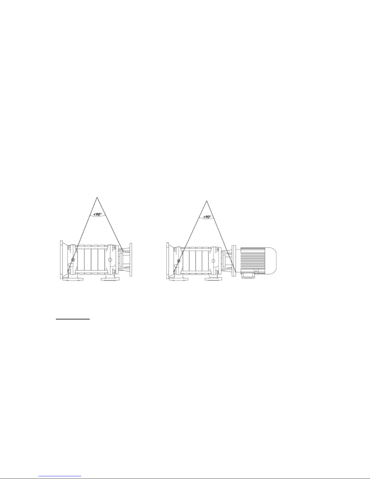
- Pump should be hoisted as it is indicated in Figure 1-1 and Figure 1-2 for not
causing any damage in pumps. Motor hanging ring should absolutely not be used
while lifting complete group.
- Load should be kept in lifted position more than required time.
- Pump and pump group should always be lifted and carried in horizontal position
Figure 1-1 Single Pump Figure 1-2 Motopomp
STORAGE
- If pump group is not immediately installed, it should be stored in a place which is
clean dry and does not include freezing and explosion risk.
- If pump bearing are type which should be greased, they should be extra greased for
preventing entry of moisture to bearings around shaft
- Pump should be protected from moisture, dust, dirt and foreign objects by covering
with suitable material. 5

- Pump shaft should be rotated a few turns (e.g once a week) for preventing pitting
around pump bearing surfaces and jamming of shaft.
INSTALLATION
Installation of pump to its place and connection setup should only be done by expert
personnel. Failed installation and pump ground may cause failures.
This situations are not covered with warranty
- If pump is supplied without motor (without motor, proper motor should be selected
prior start to installation of group.
Following properties should be considered during motor selection.
- Maximum power of pump (in all operation ranges)
- Operational revolution of pump shaft
- Necessary power supply
- Motor Type
- Motor connection type ( footed, flanged, horizontal, vertical etc. )
- If pump is purchased as single pump (without motor and chassis); a proper frame
should be constructing for putting this group over it. Frame to be constructed should
have dimensions and strength which will not permit vibration and shape defects.
Starting the motor should be done with control cabinet which is prepared according
to power of motor and floater should absolutely be used for preventing to operate
without water. Also collector diameter should be suitable with pumps efficient
operational ranges not with installation.
Before start to pump installation
- Protecting parts in discharge and suction pumps should be removed and cleaned
well.
-. Pump should be installed in a places which does not have freezing or explosion
risk and have well air conditioning.
- There should be enough space around pump for accessing pump easily and for
maintenance operations and there should be sufficient height and space for lifting
pump if necessary.
- Pump suction pipe should be as short as possible.
- You should be carefully work at pump installation ground preparation and
installation of pump group into its place. Incorrect and careless installation causes
early wearing of pump parts and failures.
6

- Pump ground should be so heavy to absorb vibrations and sturdy to prevent bends
and adjustments defects. Ground concrete should completely be solidified,
completed its plug time and proper stud bolts are placed in pump frame fixing holes
and proper fixing lugs should be placed for using in making connections with welding.
Concrete and plate upper surface should be horizontal and very smooth.
Installation
Installation of pump group to ground by anchoring stud bolts:
- Pump group is placed to center the stud bolt slots which are opened in ground
concrete.
- Anchoring stud bolts are inserted through fixing holes over pump frame fixing holes
and places into their slots.
- Pump group is places over base concrete. Water balance is placed over pump
discharge flange and horizontality of pump is controlled. If there is a horizontal
imbalance in pumps position, steel wedges are put under frame and balance of pump
group is obtained.
- Nuts of anchoring stud bolts are installed.
- Anchoring stud bolt holes are filled with concrete grout.
- Anchoring stud bolts are reciprocally tightened.
- Coupling setup is controlled in this situation.
- Concrete is poured into pump frame. Joining of poured concrete and ground
concrete is cared.
- Complete binding of concrete is controlled and anchoring stud bolts are reciprocally
tightened.
- Coupling adjustment is again controlled with template. If there is maladjustment,
coupling adjustment is made again.
- Discharge and suction flange fixings of pump are controlled again. If there are
unnecessary strains and cricks they are eliminated.
- Coupling guards are placed after coupling adjustment.
:Installation of pump group with concrete fixing plug :
- Pump is placed into ground concrete or the ground to be installed carefully.
7

Pump group frame fixing holes are marked to concrete. Pump group lifted again.
- Marked places where fixing plugs will be placed are drilled carefully according to
standards.
- Fixing plugs are carefully placed into drilled places.
- Steps for installation with anchoring stud bold are made here with same order.
Installation of Pipe Equipment
- Nominal diameter of pump discharge and suction pumps are not an indicator for
correct diameters for discharge and suction pipes. Pipes and accessories having
diameter less than pump opening diameter should absolutely not be used. Especially
bottom backwater valve, dirt retainer, filter and check valves and similar elements
should be chosen to having a larger passing area. Never use pump as a supporting
point for pipe installation or a as a carrier.
-Cricks and stresses in pipe and pipe weight equipments should be controlled
whether they effect pump. For this reason, bolts of discharge and suction flanges
should be loosen and it should be controlled whether pipe system exerts a stress
over pump.
- Never use pumps as a support point or carrier for a pipe installation
-Flow rates generally should not exceed 2m/s in suction pipe and 3 m/s discharge
pipe. High speeds cause decrease in pressure which will cause cavitations
conditions and excess friction losses in discharge pipe.
- Pipe system should be supported from points which are close to pipe
- Pipe connections should be made by flanges. Flanges gaskets should be produced
from suitable material and should have suitable dimensions. Gaskets which will be
used between flanges should be centered for not preventing water flow.
- Proper expansion equipments should be used for preventing additional forces to
pump which may occur because of expansion in systems which operate in over
vibrant and hot liquids.
8
- Welding burrs, metal particles, which may occur during pipe equipment production
sand, and oakum and similar foreign objects may present inside pump. Suction and
discharge flanges should be closed with gasket without hole for preventing those
materials enter into pump during installation. At the end of installation, all pipe parts
should be dismounted, cleaned and dyed and installed again. If dirt retained is used
at pump suction line, it should be removed and cleaned after first few days of
operation and installed again.
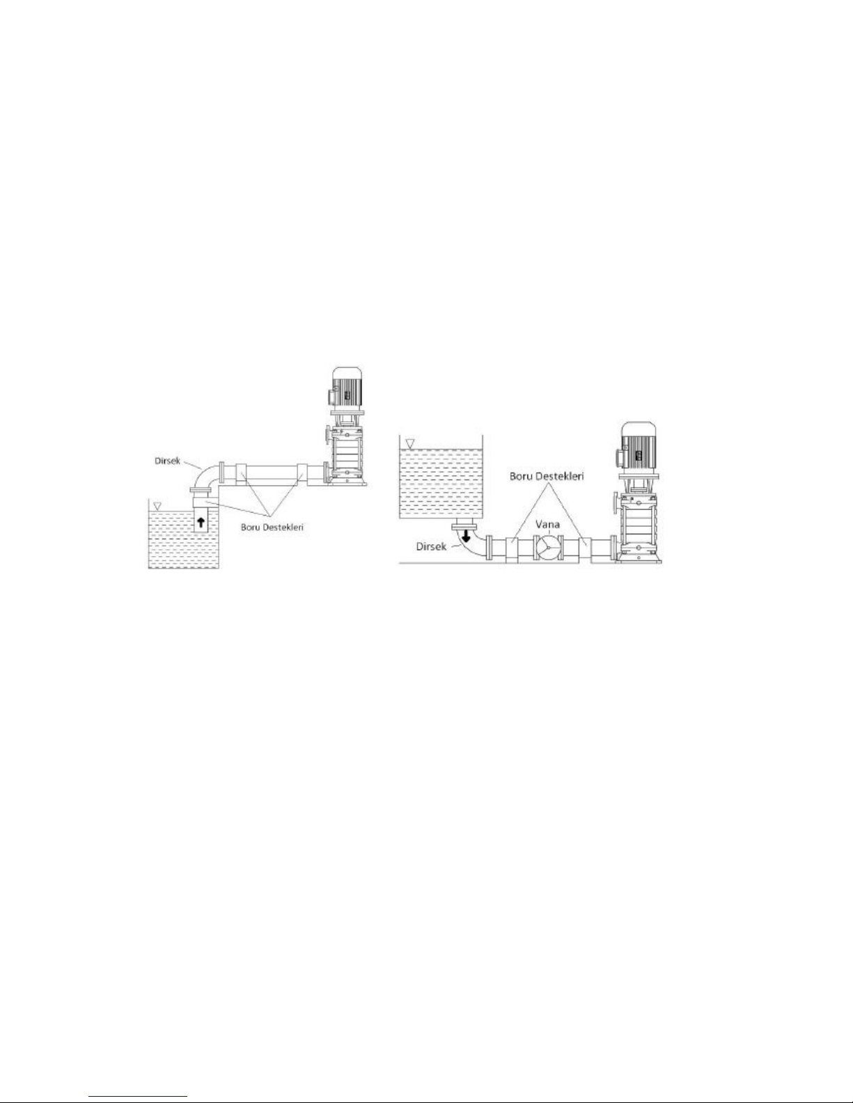
Figure 2-1Suction from Height Figure 2-2 Suction from Height
Suction and Discharge Pipe Connections
- If pump is supplied from a tank which is higher than pump, there should be an
isolation valve in suction pipe whose axis will be in horizontal position. This valve
should be completely open while pump is in operation and should never be used as
flow rate adjustment valve. (Attention: Closing valve may cause pump operation with
cavitations. )
- Suction pipe should absolutely be impermeable and should not be arranged to
cause any air wall. In this case if a tank is supplied from a tank which is higher than
pump, (suction high installation) suction pipe should be slightly decreasing sloped
towards pump and supplied from a tank which is lower than pump, suction pipe
should be slightly increasing sloped towards pump.
9

Figure 3-1Suction from Height Figure 3-2 Suction from Height
- Sharp bends should not be used, sudden direction changes and cross section
narrowing should be avoided and suction pipe should be short as possible for
keeping pump friction losses as low as possible. If there is need of cross section
change in horizontal suction pipe, an intermediate eccentric conical part whose flat
type is at upper side should be used.
-. If pump discharging height is more than 10 m or discharging line is very long, a
check valve should be placed over discharging pipe between pump and isolation
valve for protecting pump against water impulses and reverse flows during stop.
- A control valve which is close to pump should be connected for flow rate and
discharge height adjustment.
- If pump discharging height is more than 10 m or discharging line is very long, a
check valve should be placed over discharging pipe between pump and isolation
valve for protecting pump against water impulses and reverse flows during stop.
10

Auxiliary Pipe Connections and Accessories
Depending on the practice auxiliary pipe connections (necessary seal, cooling, seal
washing, watering, drain, etc and/or) pressure gauge, temperature gauge
connections can be used for controlling operational conditions.
-Pressure or vacuum gauges should be installed sturdy in measurement points
which are over flanges or very close to flanges by means of estimated 8 mm pipes
which are bended in spiral form. Air taking valves should be used for devices to
operate safely and precisely.
- There are connection places in every pump for discharging pump and removing
leakages in seal bed. (Figure 6). Those connections can be connected to discharge
tank by means of pipes if requested. There should be isolation valve in pipe which is
used for pump discharging and this valve and pipe should be suitable with maximum
operational pressure of pump.
-Seal cooling, watering and washing pipes should be connected to correct places
over pump body which are specified for them.
By-Pass Valve Connection
-. A by-pass valve should be places over discharge pipe just after pump and before
adjustment valve or outlet flange of pump if there is a case that pump will operate in
conditions that pump discharge valve is completely closed(that is with zero flow rate)
or almost closed (that is with very small flow rate). If such valve is not used and
pumps operates with closed valve for a long time, power which is provided by motor
will completely transform into heat energy and pass into discharged liquid. This may
cause over heating and abnormal failures in pump.
- Those connections can be connected to discharge tank if requested with pipes.
There should be an isolation pump over the pipe which is used for discharging pump
and both valve and pipe should be suitable with maximum operational pressure of
valve.
-Seal cooling, washing and watering pipes should be connected to correct places
over body.
11
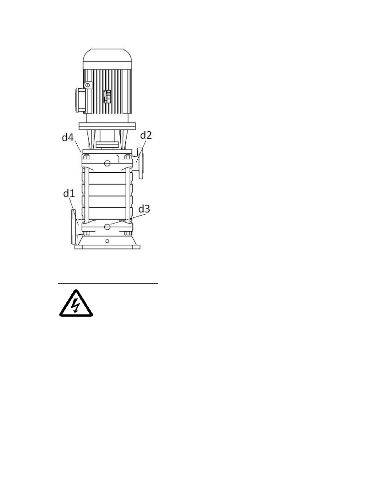
d1: Suction opening Pressure Meter Connection
d2: Discharge Opening Pressure Meter Connection
d3: Liquid Discharging Hole
d4: Seal Leakage Dİscharge
Figure4
ELECTRICAL CONNECTIONS
- Electrical connections should be done by authorized electricians
National instructions, regulations and instructions of motor manufacturers should be
obeyed.
- Power cables should absolutely be installed as not having contact with pipe
installation, pump and motor body.
- Motor shaft should be rotated by hand before making electrical conditions to control
whether it rotates easily.
- It is recommended to use PTC(Passive Thermal Control-Thermistor) in motors.
However usage of those depends on customer. If PTC is used ends of those should
be connected to motor terminal box and later should be connected to PTC control
device in motor control panel.
- Electrical motors should be protected against overloading by circuit breakers and/or
fuses. Circuit breakers and/or fuses should be selected with respect to full load
values those are written in nameplate on motor.
12

- Compare and control voltage, ampere and frequency values which are given in
motor nameplate with line values.
- Motor connection scheme can be found in motor terminal box or in handbook.
- Motor electrical connections should be done according to local Electrical
Regulations and earthing connection should absolutely be done.
- Protection class of motor body and control system cases in pump should be at least
EN 60029 IP 22. In addition to this, protection class of motor bodies and control
systems in pump group should be determined according to operational and
environmental conditions.
- Safety precautions which are determined in "Safety Instructions" should be applied.
All power connections should be disconnected before starting to any work.
- Motor connection type changes according to motor mains power and connection
type. Necessary connection types of jumpers in terminal box are displayed in Table 1
and Scheme 1a-1b and 1c
Start Type
Motor Power
PN<4kW
Motor Power
PN >4kW
Mains Power
3~400V
Mains Power
3~400V
Direct
Y-connection (1b)
Δ-connection (1a)
Y/ Δ Star Delta
Impossible
Remove Jumpers (1c)
Table 1
Scheme 1a Scheme 1b Scheme 1c
13

Attention! Transition time from star to delta should be short in star-delta connected
motors. In case that it is long damages may occur in pump and motors. (Table2 )
Motor Power
Y- Setup time
<30 kW
>30 kW
<3 seconds
<5 seconds
Table 2
- After all abovementioned operations are completed, pump rotor should be rotated a
few turns for being sure that it rotates easily.
- All safety guards should be installed into their places. Pump should absolutely be
not operated after this operation is made. This is a safety and occupational safety
rule which should absolutely be obeyed.
FIRST START
Controls Before Operation
-If there is bottom back flow water valve in pump with depth suction; they are filled
with water from filling hole in highest point and its air is taken.
- This case does not cause problem in force feed pumps. Suction valve is opened if
any. Air plugs are loosen and discharge of air and completely filling of pump is
provided.
- If system includes vacuum pump, rise of water in suction pump by means of
vacuum pump and filling pump is provided. When water reaches the highest level
pump is started.
- Pump bearings are shipped from the factory as being filled with grease which will be
enough for one year.
- Before first start of pump, bearings should be checked whether there dirt has
entered into it during shipment and installation. If bearings are dirt they should be
completely be cleaned and greased again.
- If pump has waited before installation for a long time (more than 6 months), new
grease should be inserted into bearings.
- Be sure that pump and suction pipe is completely filled with water.
ATTENTION! Never let pump run in dry conditions.
14

Determination of Rotation Direction
- ARS-D type pumps rotates in clockwise direction when you look from clutch
towards pump. This direction is shown with an arrow in pump body. Pump is
operated for a short while and checked whether it rotates in correct direction. If
protection guard is uninstalled during this operation, it should immediately be
installed after this operation.
Starting Pump
- Check that suction valve is open and discharge valve is closed.
- Close the circuit breaker and start the motor.
- Wait motor to reach full speed. (Wait motor to pass delta in motors operation with
star-delta)
- Observe the ammeter in panel and slowly open discharge valve. (If discharge pipe
is empty in first start, do not open discharge valve completely and open in controlled
way by controlling that value in ammeter is lower than motor rated values.)
Stopping the Pump
- Slowly close the discharge pump.
-. If there is water impulse prevention equipment in Discharge line and if the impulse
which may occur is not in dangerous levels, you can stop the pump without closing
the valve.
- Stop the motor. Watch that pump group has stopped calm and regular way.
- If there is external feed to seal, close this for decreasing the pressure in seal.
- If pump will be out of service for a long time close suction valve and auxiliary
circuits if any.
- If there is freezing danger and /or it will not be used for a long time, completely
discharge water inside pump by means of discharging plug over pump body. Take
necessary precautions against freezing risk.
Controls to be Made While Pump is Running
- Pump does not need any maintenance since it has mechanical seal. Very few
amounts of water may penetrate from mechanical seal but it can not ne noticed. If
water comes from mechanical seal this means that it surface is worn and needs to
be replaced. Lifetime of mechanical seal mainly depends on cleanness of discharged
water.
15

- Motor current should sometimes be controlled from ammeter over electrical panel
which controls the motor. If current values are more than motor nameplate values
there may be friction or squeezing in pump. Pump should immediately be stopped
and mechanical and electrical controls should be done.
- If there are spare pumps in system, this type of pumps should be run for a short
while at least once a week and controlled whether read for operation. Control with
auxiliary elements if any.
- Pump should absolutely be run in closed valve condition (zero flow rate) for a long
time.
- Pump should operate silent and without operation.
- Bearing temperatures should never exceed ambient temperature (more than 50ºC
). It should never exceed 80ºC
- Never operate pump without water.
LUBRICATION
-ARS-D series pump are bedded with liquid in pump shaft body and "lifetime grease
lubricated" in sliding bed and discharging body part. Entire bearings do not need
maintenance since motor bearings are lubricated with lifetime grease.
OIL CONTROL
- If pump has waited before installation for a long time (more than 3 months),
bearings should be greased. If liquid oil is used in bearings, old oil should be
removed and filled with new oil.
- Before running the pump, pump bearings should be checked whether dirt has
entered inside it. If there is dirt inside bearings they should completely be cleaned
and new liquid oil or grease should be filled.
-Oil filling or adding operations should be determined by enterprise according to
conditions in workplace and operation. This method is efficient.
-Pumps which are lubricated with liquid oil are shipped without oil. This type of
pumps should be filled with oil up to indicator level before starting to operation.
SAFETY CONDITIONS
-Works should be done by obeying workplace occupational safety rules.
-Inside of pumps should be cleaned after fluid has been discharged from pump.
-Reliability of explosive, poisonous, hot and substances in crystal structure with
respect to environment and human health should be assured.
16

-Considering that used cleaner and protector solvent wastes may give harm to
environment and human health; precautions should be taken for preventing
dissipation to environment and mixing to suction pool. Accumulation and putting the
used waste solvents in disposal area should be cared.
-Working area where dismounting and installation works are performed should be
clean.
-Pump should be free of all dangerous materials and be clean during return back.
-Lifting tools and equipments which are suitable with objective and occupational
safety should be used in dismounting and installation operations.
DISMOUNTING OF PUMP AND REPAIR
ATTENTION! - Before starting to any operation over pump always disconnect the
electrical connections and be sure that it will not run mistakenly. Certainly obey the
instructions which are given in "Safety Instructions".
Dismounting of Pump
- Close isolation valves in suction and discharge pipes.
- Open the fuses of electricity line fuses coming to motor as they will not carry current
and remove control cable coming to motor from motor terminal box.
- Open the discharge plug and discharge the water inside pump.
- If the liquid inside pump is special, discharge it after taking necessary safety
precautions.
-Uninstall the bolts of pump's suction, discharge flanges and foot.
-Disconnect pump from installation.
-Before starting to dismount pump mark the suction, discharge and stage bodies for
providing easiness during installation and mark the corresponding locations.
-Remove the clutch and other safety guards.
-Place the pump vertically from the motor carrier ground.
-Uninstall lower bearing feeding pipe.
- Uninstall pump foot from suction body.
-Uninstall lower bearing cover.
- Uninstall shaft safety nuts.
- Uninstall body stud bolts nuts and remove body stud bolts.
-Take the suction body
17

-Remove the lower bearing from suction body.
- Remove the shaft bearing and wedge.
-Take the impellor, diffuser and together with stage bodies, and last stage body
together.
-Uninstall the discharge body
-In mechanical seals first uninstall the mechanical seal cover from discharge body
and then separate discharge body from roller bearing bed.
-Lay down the pump for uninstalling the remaining parts.
-Uninstall the motor carrier.
-Separate the clutch from pump shaft by using puller and take the wedge.
-Uninstall the bearing cover with roller bearing.
-Uninstall the shaft safety nuts.
-Slightly hit the end of shaft and take the shaft and roller bearing from bed.
Take the roller bearing out of shaft.
-Uninstall the intermediate bushing and seal bushing.
-Take the two piece ring.
Installation of Pump
-. Pump installation operation is made by reverse order of pump dismounting
process. Pump cross section drawings will assist you for this subject.
-Clean all the parts, replace the damaged and worn onesç
- Before starting to installation operation, apply lubricious materials such as graphite,
silicone or similar slippery substances over contact surfaces or bolt surfaces. If you
can not find those substances use liquid oil. (drinking water pumps excluding
- Do not use gaskets which you had removed. Use new ones having same
dimensions. Be careful that new gaskets and O-rings are in same dimensions.
Pumps with Mechanical Seal
- Water leakage does not occur in a mechanical seal which properly operates.
Mechanical Seal does not need maintenance in cases that it does not have visible
water leakage. Besides this impermeability of mechanical seal should be regularly
controlled.
- Strictly obey the instructions of mechanical seal manufacturers instructions in
pumps where mechanical seals are used. Never run mechanical seal in dry
conditions.
18
Table of contents
Other Sempomp Water Pump manuals

Popular Water Pump manuals by other brands


OEG
OEG N Series operating instructions

Thermo Scientific
Thermo Scientific Surveyor LC Pump Plus Hardware manual

Bestway
Bestway Sidewinder 62142 manual

Jefferson Professional Tools & Equipment
Jefferson Professional Tools & Equipment JEFSUBPIDW260-11 user manual

ProMinent
ProMinent Dulco flex DFBa Series operating instructions

Crivit
Crivit 285656 instruction manual

Urrea
Urrea 2363V User manual and warranty

Pentair
Pentair AURORA 3801 Installation and operation manual

BUSCH
BUSCH COBRA NX 0450 A instruction manual

Liberty Pumps
Liberty Pumps LCU-15 installation manual

Simplex
Simplex PET SERIES Operating & maintenance instructions

Panduit
Panduit CT-902HP Operation and maintenance