MRC HR-150AS User manual

Digital Display Manual
Rockwell Hardness Tester
HR-150AS
3, Hagavish st. Israel 58817 Tel: 972 35595252, Fax: 972 3 5594529
MRC. 10.23

1
Contents
1, Summary…………………………………………………………………………1
2, Application of hardness meter…………………………………………………2
3, Main technical parameters………………………………………………………3
4, Performance indicators ………………………………… …………………4
5, Use instructions……………………………………………… …………………4
6, product appearance…………………………………………… ………………5
7, Introduction of mechanism performance…………………… …………………6
8, Installation of hardness meter………… ………………… …………………7
9, Methods of operation and precautions………………………… ………………7
10, maintenance and calibration of hardness meters……………… ……………11
11, Statement of status …………………………………………… …………12
12, Packing list.…………………………………………… ……………………16
13, Certification…………………………………………………… ……………17
14, Warranty card…………………………………………… …………………18

ISummary
1, What is Hardness
It is the ability of material to resist elastic deformation, plastic deformation or
destructive force. For indentation hardness tests, hardness is the ability of a substance to
resist the indentation of another harder object of a certain shape and size into its surface.
2, The principle of Rockwell hardness Test
The Rockwell hardness measurement method is to press the test force F1 into the
surface of the specimen under the action of two test forces (initial test force Fo and total
test force F) applied successively with a specified pressure head. After the total test force is
maintained for a certain period of time, the main test force F1 is removed. Retaining the
initial test force, measuring the indentation depth H 1, indicating the Rockwell hardness by
the difference between the indentation depth H 1 and the indentation depth ho under the
action of the initial test force, and taking the axial displacement of the head as a Rockwell
hardness unit, Generally read directly from the dial, the principle of which is shown in the
following figure.
Rockwell hardness is shown by the following formula HR=K-
Type center C——Commonly used equal to 0.002mm
K——Constant when the diamond cone holder is used to 100,
When the ball head is used 130
Rockwell hardness test principle diagram
3, Characteristics of Rockwell hardness test
Rockwell hardness test adopts the method of measuring indentation depth, hardness
value is read out directly by indication, so it is simple and easy to operate, easy to master,
high work efficiency, suitable for the inspection of batches of parts and components.
Rockwell hardness test method can be used to measure hard and soft samples with
diamond head and rigid ball head. Therefore, Rockwell hardness test has been widely used
in production and has become a test of product quality. Determine the main testing means
of reasonable processing technology. Rockwell hardness tester is the most commonly used
testing instrument for hardness test, teaching and research work in production enterprises,
universities and colleges and scientific research institutions.
2

3
II Application of Hardness Tester
Rockwell hardness test can choose different pressure head and test force according to the
range of,material hardness and different test thickness, and use different scale to express it.
The most commonly used scale is Agni Bian C scale. The test force and pressure head of
common scale are given in the following table. The numerical value of constant K and its
Application range and an example of its Application.
Range of use of Rockwell hardness meter
Rockw
ell
hardne
ss scale
Hardn
ess
symbol
Head type
Initial
test force
Fo(kg.)
Main test
force
F1(kg.)
Total test
force
F(kg.)
constant
scope of
application
Applicati
on
example
A
HRA
Diamond
cone head
10
50
60
100
20-88HRA
Hard
metals
and
cemented
carbides
B
HRB
Diameter
1.5875mm
ball head
10
90
100
130
20-100HRB
Nonferro
us metals
and soft
metals
C
HRC
Diamond
cone head
10
140
150
100
20-70HRC
Heat-trea
ted
structural
steel, tool
steel
D
HED
Diamond
cone head
10
90
100
100
40-77HRD
Surface
quenched
steel
F
HRF
Diameter
1.5875mm
ball head
10
50
60
130
60-100HRF
nonferrou
s metal
G
HRG
Diameter
1.5875mm
ball head
10
140
150
130
30-94HRG
Pearlite
iron,
copper-ni
ckel, zinc
alloy

4
HRA:Suitable for the determination of metals whose hardness exceeds 70HRC,
such as tungsten carbide, cemented carbides, hard sheet materials and surface
hardened materials.
HRB:Used for the determination of soft or medium hardness materials such as
non-ferrous metals and their alloys, annealed steel or unhardened steel products.
HRC:Used to determine the hardness of heat-treated steel products such as
carbon steel, tool steel and alloy steel.
IIIMain technical parameters
1、Initial test force 98.07N(10kgf)
2、Total test force 588.4N(60kgf)980.7N(100kgf)1471N(150kgf)
3、indicator Digital display
4、Maximum height of specimen When the lead screw protector is added100mm
Without a lead screw cover170mm
5、Indentation center distance to machine wall 135mm
6、Hardness gauge shape dimensions 466×238×630mm
7、Hardness gauge net weight 65kg
IV Performance index
1、Support HRA, HRB, HRC hardness scales;
2、Very low power consumption, long service time, this product is powered by
CR2450 battery.
3、with HV,HB hardness conversion function.
4、the resolution is 0.1HR.
5、with time display.
6、with data output function, can be connected to the computer or serial micro
printer;

5
VDirection for use
Initial Status
Increase Test Anvil and Touches
Indenter, start initial fore displays
295-305
If exceed 305,
then redo it
Start main force,
then timing
If index to 0, then
redo it
Reach to set time, unload
main force, show hardness
value on screen
If abnormal value,
redo it
Decrease test anvil,
remove initial force
Make next test
Calculate Average Value

VI Product appearance
1、ZERO/ON keystroke: short press reset, long press shut down;
2、Set key: short press select scales, long press clock setting;
3、CLR key: short press clear current measurement data;
4、Out key: long press output data;(recording data to a predetermined number of effective)
5、COVN key: short click average, long by switching conversion unit;
6、number button: set the average of test counts, max 9;
7、data output;
8、battery box
6

Print output format
Hardness data output to printer or computer in ASCII code, baud rate
38400,n,8,1,The output format is as follows:
2014-9-27 16:40(time)
No HRC(Serial number)
01 61.2(first hardness test)
02 61.0 (second hardness test)
03 60.8 (3rd hardness test)Avg 61.0
7
1、conversion units
8、force applied
2、conversion results
9、unit of force
3、Time indication
10、Mean value mark
4、Unit conversion mark
11、surveyor's rod type
5、power shortage alert
12、Surface Rockwell type supplement
6、hardness value
13、average total
7、head type
14、average current count

VII Brief introduction of Mechanism
performance
The hardness gauge consists of a fuselage, a test force applying mechanism,
a measuring indicator mechanism and a test piece support mechanism (see figure
1). The fuselage is a closed shell. Except for the table, the lead screw and the
handling handle, the other mechanisms are all installed in the fuselage shell to
keep clean.
The test force exerting mechanism consists of spindle, lead screw, blade,
weight buffer, weight transform mechanism, handle and so on.
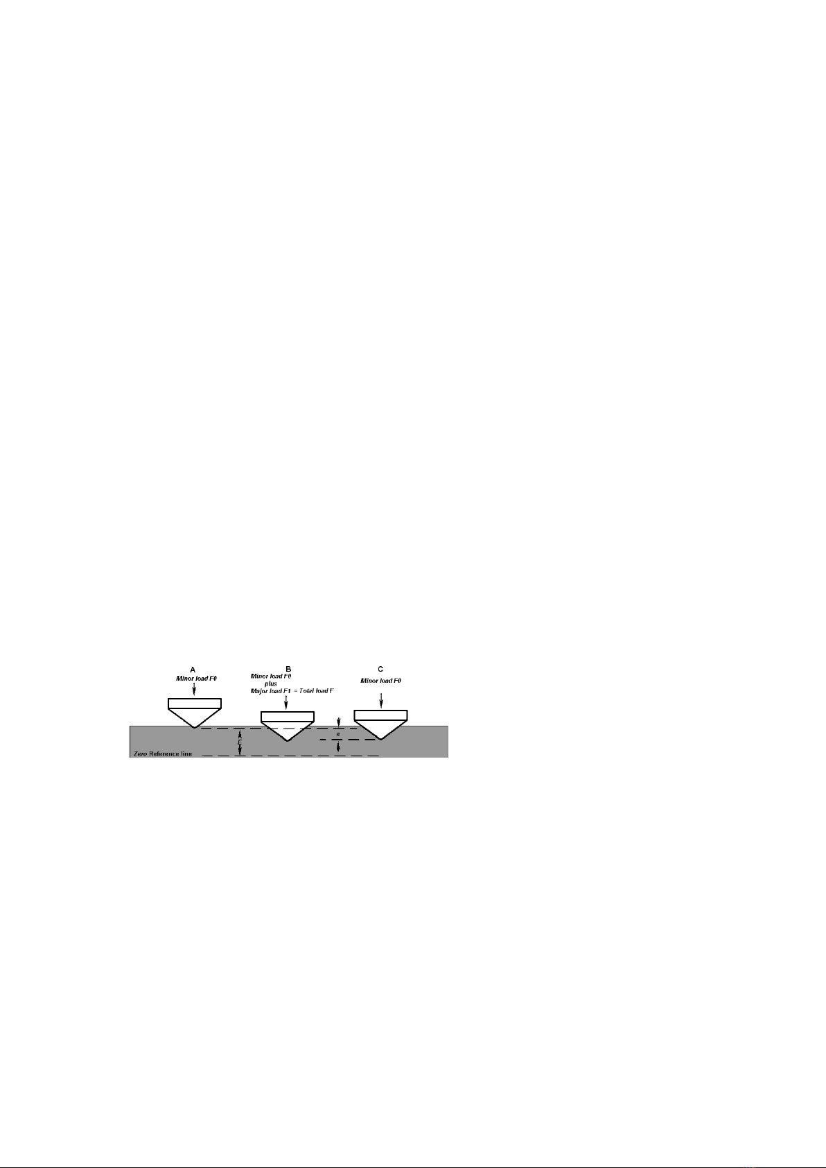
The initial test force is mainly caused by the weight of parts such as spindle
(1) circular knife (2) long diamond knife (3) large lever (4) and small lever (21)
and the measuring pressure of indicator (24). When the specimen is in contact
with the pressure head and continues to rise so that the large and small lever is in
the horizontal position (indicator small pointer refers to Yu Hong point, the large
pointer is vertical up) due to the weight of the lever, etc., and the measuring
pressure of the indicator, The head can be subjected to (10kg) 98.07N of the
initial test force.
The total test force is composed of the main test force (generated bythe
weight of the weight) plus the initial test force, and two weights (10) and a hanger
ring (11) are arranged on the rack shaft (8) of the buffer (7). When the piston of
the buffer is lowered by the pull handle (15), the rack shaft (8) top rod (9) and
the hanger ring (11) weight (10) are also lowered with the pull handle (15), The
weight of the weight (10) and the ring (11) acts on the large lever (4) so that the
head is subjected to the total test force.
The fuselage is equipped with a weight variable load frame (12). When the
handle (13) is rotated to different positions, three different total test forces of
1471N or 980.7N or 588.4N can be obtained.
The oil needle (14) is used to apply the main test force to maintain a certain
speed and to avoid the impact phenomenon.
The handle (15) is used to apply the main test force, and the handle (16) is
used to remove the main test force. When the handle (15) is pulled, the cam (17)
and the gear (19) begin to rotate, and the rack shaft (8) push rod (9) and the
buffer piston fall with each other, At the same time, the handle (16) is rotated
8

counterclockwise, and the main test force can be fully applied when the ring is
supported by a small knife (20) at the end of a large lever during the descent.
The measuring index mechanism is composed of a small lever (21), a lever
(5), an adjusting plate (22), a connecting rod (23) and an indicator (24), etc.
When the head of the rising specimen is pushed up, the lever (5) pushes up the
small lever (21) to rotate the pointer of the indicator through the connecting rod
(23).
The specimen support mechanism includes a worktable (25), a lead screw
(26), a handwheel (27), a lead screw seat (31), a protective sleeve (29), a flat
bearing (30). It is worth mentioning that compared with the same type of
hardness meter of other manufacturers, the hardness meter has increased the
protective cover (29) and the plain bearing (30) to avoid dust and debris sticking
to the support surface during use, thus reducing the wear on the support surface.
Thus, the operation is more lubricating and smooth, and the indication value is
more accurate and stable.
VIII Installation of hardness gauge
1、Unpacking(see figure 2)
(1)、By opening the top cover of the box and removing the four screws at
the bottom of the fuselage, the hardness meter can be installed in a dry, clean,
non-corrosive gas and vibration-free room. The hardness gauge table should be
sturdy and make holes larger than Φ50 mm in diameter for the lead screw to
pass through.
(2)、Check the completeness of accessories according to packing list.
(3)、open the upper cover (6) and the rear cover (19).
(4)、 loosen nut (8) remove hook head screw (9).
(5)、 remove the large lever fixed block (7) and the fixed support block
(1).
(6)、 release nut (13) remove hook head screw (12) remove weight fixed
pressure plate (14)
(7)、 hold the ring (10) with your hand and slowly lift up the weight
group (17) and remove the weight fixing support block (18) at the same time,
then gently drop the weight group (17). The weight cylinder pin (15) falls into the
groove of the bracket plate (16) to hold the weight.
9

10
页
(8)、release of small lever fastening cord (4)
(9)、 turn the handwheel (1) to lower the lead screw (2) and remove the
pressure head pad (3).
2、Unload the screw protector (30) with kerosene to wash the rust oil from
the lead screw, handwheel, etc., then pour a small amount of lubricating oil into
the contact place between the screw and the handwheel, and reapply the screw
protection suit.
3、Check that the position of the adjustment block (6) on the large lever (4)
is between two red marks, otherwise it should be reloaded into the correct
position.
4、Install the large flat table on the top of the lead screw (26) and place the
level on the surface of the table. Four bottom angle horizontal adjustment bolts
are mounted on the bottom of the fuselage to adjust the levelness of the hardness
meter to within 0.2 / 1000.
IX Operating methods and precautions
1、Preparatory work before the test
(1)、Adjust the application speed of the main test force: the handle (16) is
placed in the unloading position, the hand (13) is transferred to the 1471N
position, the standard hardness block of the 35-55HRC is placed on the
worktable, the hand wheel (27) rotates the hardness block up the spindle, and the
initial test force is added. Pull the handle (15) with the main test force, observe
the large pointer of the indicator, and the time from start to stop shall be within
the range of 4-8 seconds. If it does not conform, the rotating oil needle (14) shall
be adjusted and repeated until the appropriate time.
(2)、 Choice of test force: select test force according to need
(reference-range of use). Turn (13) to point the selected test force at the red dot,
but it must be noted that the handle (16) must be placed in the unloading state
(that is, the post-limit position) when changing the test force.
(3)、Install head: select the appropriate head according to the range of
use. When installing the head, attention should be paid to eliminating the gap
between the head and the end face of the spindle (1). The elimination method is
to install the pressure head and screw (28) to fix it gently, then place the standard
block or specimen on the worktable, rotate the handwheel (27) with the initial
test force, pull the handle (15) so that the main test force is applied to the
pressure head, Tighten the screw (28) and eliminate the gap between the head

11
页
and the spindle face.
(4)、Preparation and selection of specimen
The specimen should have a certain size and thickness, and the distance
between the adjacent indentation center and the edge of the specimen should
be more than 3 mm, and the minimum thickness of the specimen should not
be less than eight times of the indentation depth. After the test, there shall be
no obvious deformation marks on the supporting surface of the specimen.
The minimum thickness of the specimen depends on the material and the
load used. Please refer to the following table of the minimum thickness of the
specimen.
Sample minimum thickness table
surveyor's
rod
hardness
value
HR
minimum
gage
(mm)
surveyor's
rod
hardness
value
HR
minimum
gage
(mm)
A
70
0.7
B
80
1.0
80
0.5
90
0.8
90
0.4
100
0.7
B
25
2.0
C
20
1.5
30
1.9
30
1.3
40
1.7
40
1.2
50
1.5
50
1.0
60
1.3
60
0.8
70
1.2
67
0.7
Generally, the specimen is plane. If the surface specimen is tested, if the
curvature radius is small, the test result should be corrected. For convex
specimens, corrections should be added, and for concave specimens,
corrections should be subtracted. The correction of cylindrical specimens
can be referred to below table。

12
页
The table surface of the specimen must be polished or polished, the
roughness of the table surface shall be not less than 1.6, and the hardness of
the material shall not be affected during processing, that is, the
working-hardening or tempering should not occur, the roughness of the table
surface of the supporting surface shall not be less than 3.2, and the working
face of the specimen, The supporting surface and the working table surface
should be clean and free from oil pollution. The sample should be placed
smoothly on the worktable, and no movement should occur during the test.
The specimen must be installed to ensure that the applied test force is
perpendicular to the test surface. For specimens with bending and other
irregular shapes, the appropriate type of special worktable must be adopted
and the correct test position should be selected. For example, for cylindrical
specimens, a "V" worktable must be used.
2、Test procedure
①Wipe the top face of the lead screw (26) and the upper and lower
face of the selected worktable, and place the worktable on the upper side of
the lead screw (26).

13
页
②Wipe the test piece support surface and place it on the workbench.
Rotate the handwheel (27) to make the table rise slowly, and push up the
indenter. The small pointer to the indicator points to the red dot, and the
large pointer rotates three times vertically upwards (allows a difference of ±5
scales, if more than 5) Scale, this point is void, retest). Note: When the
workbench is raised, there is absolutely no backlash.
③Display (24) Digital Clear Press the zero button on the display .
④Pull the loading handle (15) and apply the main test force, when the
display number drops.
⑤The unloading handle (16) can be pushed back in 2-3 seconds to
remove the main test force after the display digital change has been
significantly stopped and maintained for 15 seconds. Note: the application
and removal of the main test force should be carried out slowly and without
impact.
⑥Turning the handwheel causes the specimen to drop, then move the
specimen, and carry out the new test according to the (2)-(6) process above.
Note: the specimen must be moved close to the working table. B: must
ensure that the distance between the adjacent indentation center and the
center to the edge is more than 3 mm; C: normally, the first test is only used
to offset the gap between the supporting surfaces, the test results are not
counted, should be from the second point statistical test results.
⑦The lead screw cover (30) is designed to protect the lead screw (26)
from dust. When the hardness meter is not in use or when the specimen
height is less than 100 mm, cover it outside the lead screw. When the height
of the specimen is more than 100 mm, it must be removed so as not to raise
the table and invalidate the test.
XMaintenance and Adjustment of hardness
Meter
1、The hardness meter should be used in a clean, vibration-free

14
页
environment with a temperature of 25 ±10 ℃.
2、Cover the machine with a dust-proof cover when the hardness meter is
not used for a long time.
3、Regular injection of a small amount of oil at the interface between the
lead screw (26) and the handwheel (27).
4、If it is found that the indication error of the hardness meter is large, (1)
the worktable can be removed to check whether the contact surface with the
lead screw is clean; (2) the lead screw protective sleeve is checked to raise the
working table surface; and (3) the pressure head is checked whether the head is
damaged or not.
5、If the main test force is applied, the display number starts to rotate
quickly and then slowly, indicating that there is too little oil in the buffer. At this
time, the felt pad at the upper end of the buffer (7) can be lifted, and the clean
oil 20# is slowly injected. At the same time, the handle (15) (16) is pulled
multiple times so that the piston moves up and down many times, leaving all the
air in the buffer out until oil overflows from the top when the piston sinks to the
end. Note: due to the influence of temperature on the oil in the cylinder oil is
easy to produce thin and thick changes, thus affecting the loading speed, the oil
needle (14) should be adjusted according to the situation to meet the use
requirements.
6、Check the precision of the hardness meter regularly with the standard
hardness block worn by the machine。
Wipe the worktable and standard block clean, test on the hardness block
working face, never allow the test on the supporting surface.
(2)If the error of indication is great, in addition to checking according to
item 4 of this section, we should also check if there are burrs on the support
surface of standard hardness blocks, and if there are burrs, use oil stone to
polish。
(3)If the error of indication is great, in addition to checking according to
item 4 of this section, we should also check if there are burrs on the support
surface of standard hardness blocks, and if there are burrs, use oil stone to
polish。
(4)The indication value adjustment of the hardness meter: if through the
above work, the indication error of the hardness meter is still large, and the
precision requirement of the indication value can be achieved by adjusting the

15
页
front and back position of the plate (22). The method is to loosen two M 3 screws
on the adjusting plate (22) and move the position of the adjusting plate (22) back
and forth. Note that when moving toward the indicator direction, the indication
value increases, otherwise the value decreases. After adjustment, fasten the two
M 3 screws that have been released. If it is found that the pointer of the indicator
is not vertically upward, the back cap on the M3 screw in the middle of the
adjusting plate can be loosened, and the screw can be rotated to make the pointer
meet the requirements.
(5)If the user has any other questions, contact the manufacturer in time to
get the correct solution. It is strictly forbidden to disassemble by oneself to
prevent unnecessary loss.
XI State description
1.Power on initial state
Short press [SET] key to set surveyor's rod type, head type and obvious
with change, long press [SET] key to set the time limit, detailed operation see
step 7, press [NUM] key, can change the average total, range of 1, 9, Press
[CLR] key to clear the most recent measurement data, long press [OUT] key
output data, the number of times when the keys are valid, the third row show
"TM12:08" table current time is 12:08;
2、Preloading
If the third row "OOO;" continues to increase initially, the third row
flashes the EEE warning error when it exceeds 305. After the error, the
processing of the next step will not be entered, until the initial measurement
is completely removed, the displacement of the probe is 0, and the initial state
of the power on is restored. If the probe leaves the component completely and
the data is likely to be below zero or negative, press the [ZERO] key to reset,
and the [HRC] symbol begins to appear.
3、Applying the main test
After the initial preloading is in place, the main measurement will be
applied, the displacement data of the probe will change, and the third row
will begin to show the main test addition time, in seconds, the most measured
time is 99S.
Note: in this process, if the head displacement continues to decrease back to
zero, the system will judge that the operation is incorrect, and the hardness
meter will return to the initial state of electrification, requiring a new

16
页
measurement.
4、Remove the main test
When the timing time comes, the main test can be removed, the second
time display disappears, the HRC symbol is lit up, the hardness meter starts
to show the actual hardness value, at this time, the system will show the
maximum value recorded in the measurement process; After the stability of
the most measured values, the [NUM] bond and [CONV] bond can be long
pressed into the lever correction state, and the body operation can be seen in
step 8. During this process, if the hardness value display exceeds 100.0 or 130,
the third row flash EEE, needs to withdraw the initial remeasurement.
5、Remove preloading
When the data is stabilized, after removing the preload, the probe will
begin to decrease, the displacement data will change, but the hardness
display position will remain the original data, and the measurement result
will be explicit. In the average window, the counting value will be added 1; At
this time, press [CLR] key to give up the measured data, the calculated value
will be reduced by 1, show the last measurement results, reduced to 0 time
back to the initial bound; When the measurement result is explicit, the long
press [CONV] key can switch the conversion unit, and the conversion value
will change accordingly, but beyond the range will show the FFFF; when the
calculated value is equal to the total number of the average, the short press
[CON] V] key hardness value will show the average value, and the "-"
symbol on the HR will flash, then press [CONV] key to exit the average value
display, and the symbol will stop flashing; if the measurement continues, the
count will remain the same, and the measured data will not be stored. At this
point, you can long press the [OUT] key to output data to a printer or
computer.
6、Next measurement
The probe will be lifted again, and when it comes to the next
measurement, jump to step 2; You can also press [ZERO] to jump to step 1,
that is, to return to the initial state of electrification, and in the process of
steps 1 to 4, if you press the [ZERO] key, the hardness meter returns to the
initial state of electrification.
7、Time setting
Press the [SET] key at the initial state length and enter the clock setting state,

17
页
as shown in the figure:
The position of the dot matrix is Ytable year, the third row is the year.
Of which "14" flashed,
Short press or long press [CLR] to add 1; continue to press SET shortly
The keys will flash M, D, H, m in sequence.
Time division, short press in the process
[CLR] key corresponds to flashing data plus 1, long press
[CLR] button can be added quickly; shortly press [SET] after the minute
setting is completed. Key, exit time modification and save, return to the
initial state; throughout the process
Press the [ZERO] key to exit the time modification without saving.
8、Leverage correction
In step 4, press the [NUM] key and the [CONV] key to enter the lever
correction state.
The third row will be corrected in length, and the initial correction will be 1.000.
Press [CONV] to repair.
Is increasing by 0.001, long press is increasing continuously;
[NUM] key correction minus 0.001, long
Press to decrease continuously. The hardness value will change with the
coefficient of the example.
The corresponding changes. When the hardness value is adjusted to the value,
Press the [SET] key momentarily to save the correction factor and exit the
correction status.
Go back to step 4. If you withdraw the initials during this process
The hardness tester will exit the lever correction to display the current
measurement result.

18
页

19
页
Table of contents
Other MRC Test Equipment manuals
Popular Test Equipment manuals by other brands

Mastech
Mastech ms5908 Operation manual

Humboldt
Humboldt Digital MasterLoader HM-3000.3F product manual

PeakTech
PeakTech 1145 Operation manual

Tektronix
Tektronix Keithley CS-1546 quick start guide

Besantek
Besantek BST-VM04 instruction manual

TSI Instruments
TSI Instruments DICKEY-john GAC 2700-LF quick start guide