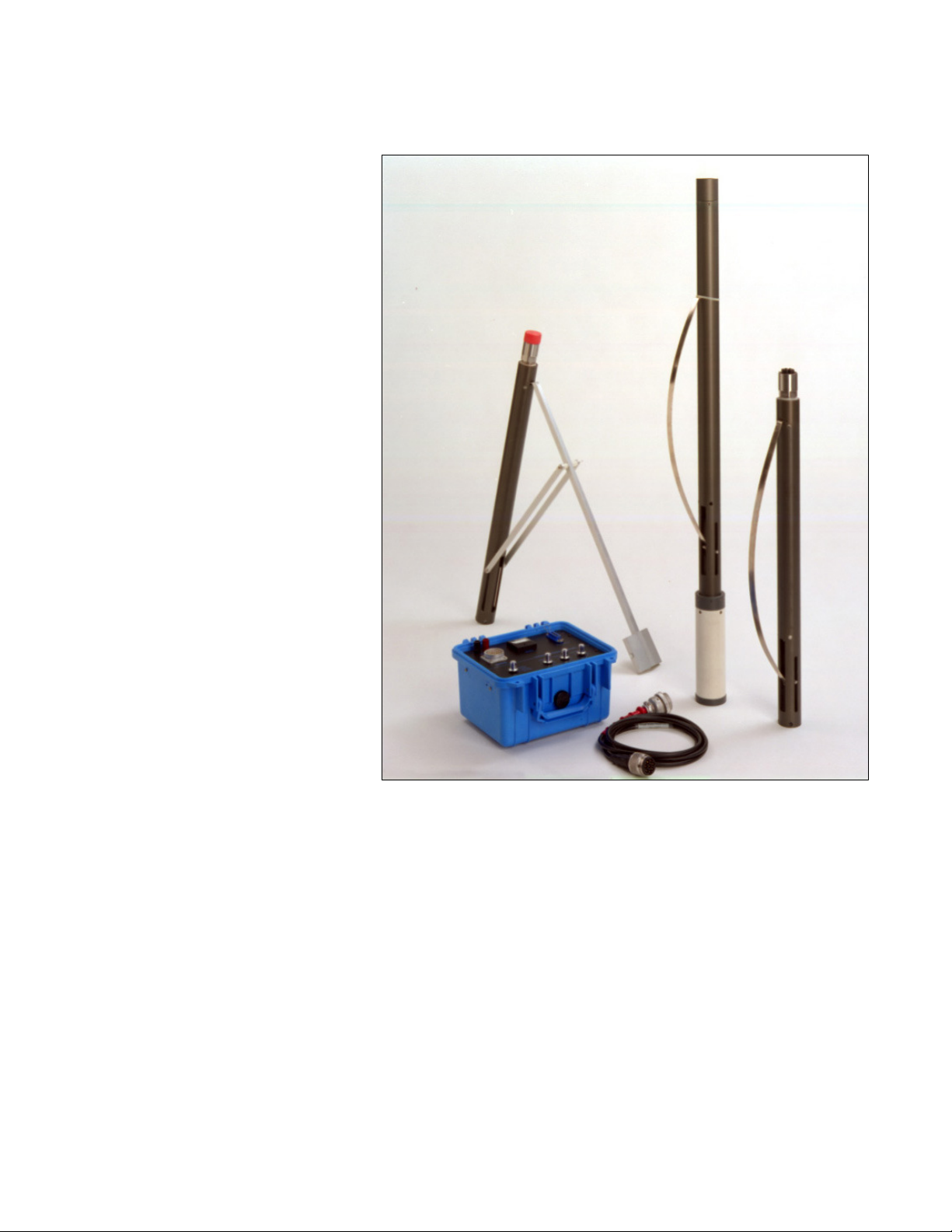
BHG-2 Borehole Geophone
The BHG-2 is a 3-component, borehole
geophone with a motor-driven clamp to hold the
geophone in place against the wall of a borehole.
The BHG-2 can be used for a variety of borehole
seismic surveys, including down hole and cross
hole. The geophone elements are oriented in an
X-Y-Z pattern. The Longitudinal geophone
points toward the clamp spring. The geophone is
slightly less than 2 inches (50 mm) diameter and
can operate in holes of at least that diameter. The
BHG-2 will fit inside a Schedule 40, 2-inch PVC
pipe, but not Schedule 80, 2-inch pipe.
The spring and geophone expand to
slightly over six inches (15 cm) wide.
An optional big hole adaptor is available
for use in larger diameter boreholes.
The clamping mechanism is a steel
spring which is compressed and
expanded by a piston actuated by a DC
motor. The motor and the vertical
geophone element share a common pair
of wires. A voltage high enough to
overcome the resistance of the cable is
applied to the appropriate conductors
and the motor retracts a piston,
expanding the spring. Reversing the
voltage reverses the motor, collapsing
the spring. The current drain provides
the operator with a measurement of how
much work the motor is doing, and
indicates when the spring is pushing
against the wall. This can be confirmed
by pulling up on the cable when it is in a
hole.
The cable may be supplied with bare
wires or a Cannon NK-27-21C which
will mate with either BHGC controller.
If your seismograph also features
Cannon NK-27 connectors, you may
connect the cable directly to your
seismograph. In that case, the Vertical
component will be connected to pins 1
& 2 (usually channel 1 on a 12-channel
seismograph, or channel 12 or 13 on a
24-channel seismograph). The
Longitudinal geophone will be
connected to pins 3 & 4, and the Transverse
geophone will be connected to pins 5 & 6. The
Longitudinal geophone points toward the clamp
spring.
To operate the clamp mechanism without a controller,
apply a DC voltage directly to pins 1 & 2 of the
connector. If the positive terminal is connected to pin
1 and the negative to pin 2, the spring will expand
against the borehole and clamp the geophone in place.
Reverse the connection to collapse the spring and
release the geophone. Verify proper operation before
putting the geophone in a hole.
The supply can be any convenient DC source,
including standard flashlight batteries connected
in series. The power supply voltage needs to be
high enough to drive 1 amp through the motor
and the cable resistance (24 volts is usually
sufficient and a good choice for most cable
lengths).
With the geophone disconnected, and pins 1 and
2 shorted on one end of the cable, measure the
resistance between pins 1 and 2 on the other end
to find the round-trip total resistance. Using
Ohm=s Law, calculate the voltage required to
push 1 amp down the cable
1
. The voltage
required will vary from 18 to 48 volts (or even
more for long cables) depending on the cable
length (see the discussion in the BHGC
instructions).
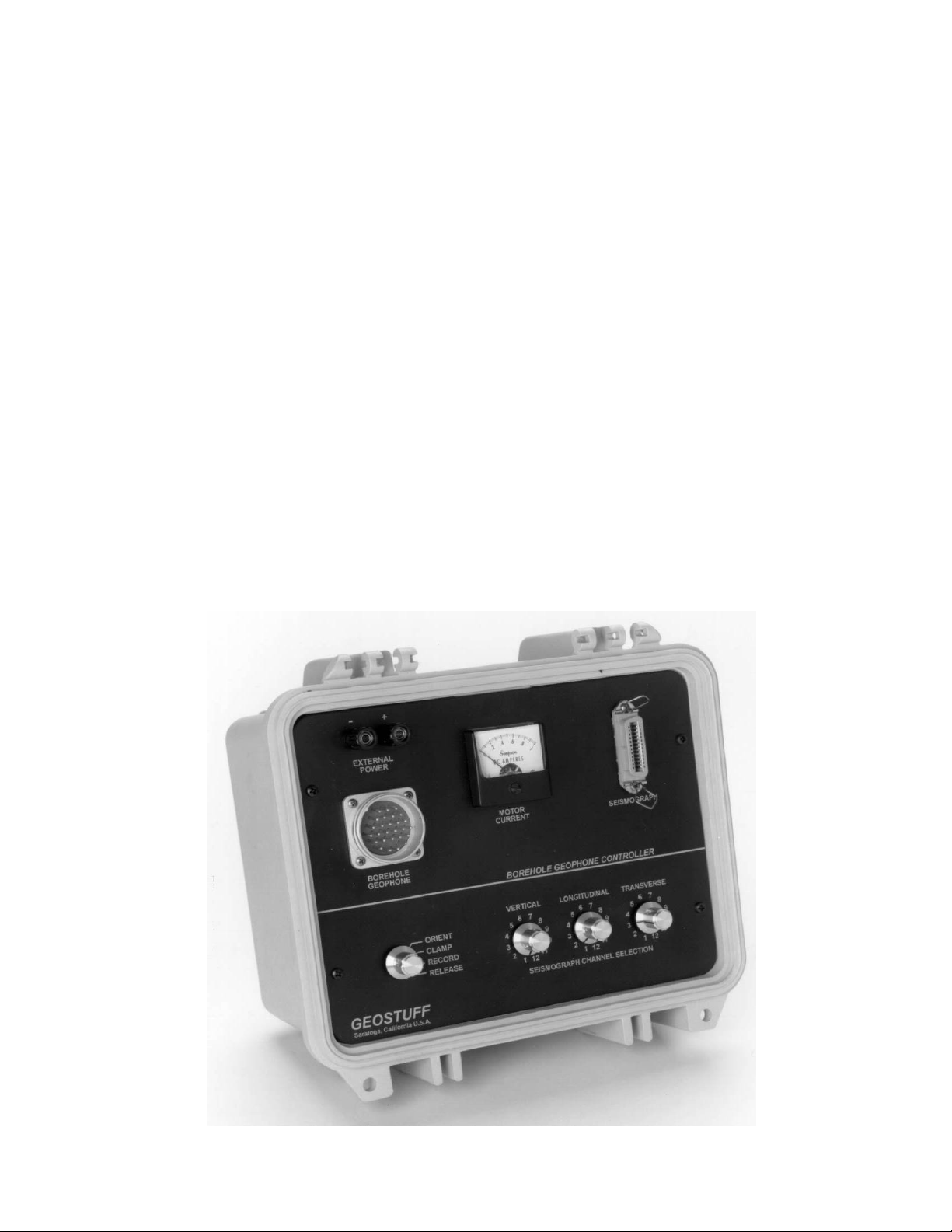
A schematic for a suitable controller is included
in this manual, or it may be operated with the
Geostuff Model BHGC-1 or BHGC-4 controller.
The motor will draw 1/3 to 1/2 amp when
moving the spring. As the spring presses
against the wall, the current will increase,
usually to about 1 amp depending on the
voltage and cable resistance. Practice at the
top of the borehole to determine how much
current is required to clamp the geophone in
the borehole.
1
Use Ohms Law, E = I*R. If the resistance equals
18 ohms, Then 18 volts will be needed to push
1 amp down the cable. Round up to 24 volts.