Sena Promi SD 205-OA User manual

USER MANUAL
Version 2.0.2 (2006.06.07)
Promi SD™
205-OA
Bluetooth RS232C Serial Adaptor
by Bluetooth
Enabling Wireless Serial Communications

FCC CONCERNS
FCC Compliance Statement
This device complies with part 15 of the FCC Rules. Operation
is subject to the following two conditions:
(1) This device may not cause harmful interference, and
(2) This device must accept any interference received,
including interference that may cause undesired operation.
This equipment has been tested and found to comply with the limits for a Class B digital device, pursuant
to part 15 of the FCC Rules. These limits are designed to provide reasonable protection against harmful
interference in a residential installation.
This equipment generates, uses and can radiate radio frequency energy and, if not installed and used in
accordance with the instructions, may cause harmful interference to radio communications. However, there is
no guarantee that interference will not occur in a particular installation. If this equipment does cause
harmful interference to radio or television reception, which can be determined by turning the equipment off
and on, the user is encouraged to try to correct the interference by one or more of the following measures:
- Reorient or relocate the receiving antenna.
- Increase the separation between the equipment and receiver.
- Connect the equipment into an outlet on a circuit different from that to which the receiver
is connected.
- Consult the dealer or an experienced radio/TV technician for help.
RF Exposure Statement:
The equipment complies with FCC RF radiation exposure limits set forth for an uncontrolled environment
This device and its antenna must not be co-located or operating in conjunction with any other antenna or
transmitter.
Do not
Any changes or modifications to the equipment not expressly approved by the
party responsible for compliance could void user’s authority to operate the
equipment.

Promi SD205-OA User Manual – Table of Contents 1
zPromi SD205-OA
Bluetooth Serial Adapter
SD205-OA
Part Number Promi SD205-OA
Description External type wireless serial adapter with dip switch
Bluetooth Power Class Class1
Frequency range 2402 MHz~2480 MHz
Number of channel 79ch
Modulation Method GFSK
Communication Method Half Duplex
RF Range Up to 100m
Operating Power range DC5V / 2A(AC100~240V / 50~60Hz)
Operating Temperature range -20 ~ +55°C
Operating Humidity range 95%
Power Connector DC plug or 6 pin
Serial connector Male DB9
Serial Interface RS-232
Serial Data Rate 1,200 ~ 230,400 bps
Dip switch Yes (4 slots)
Profile Serial Port Profile
Applicable Antenna HelicalAntenna, DipoleAntenna, PatchAntenna
Dimensions (H¯W¯D) 62.5x31.2x16.3
Includes HelicalAntenna, DC power cable

Promi SD205-OA User Manual – Table of Contents 2
Table of Contents
1. Getting Started
Components --------------------------------------------------------4
Assembly ------------------------------------------------------------- 4
Locating the Controls ------------------------------------------ 5
2. Configurations
Operation Modes ------------------------------------------------- 7
LED Indicators -----------------------------------------------------8
Serial Ports ---------------------------------------------------------- 8
Reset to Factory Defaults ------------------------------------- 8
Terminal Program ------------------------------------------------ 9
Dip Switch ------------------------------------------------------------- 10
Pairing Button ----------------------------------------------------------10
3. Connections
RS232 Interface --------------------------------------------------- 13
Pin Assignment ---------------------------------------------------- 14
Power Supply ------------------------------------------------------15
4. Specifications
Bluetooth ----------------------------------------------------------- 17
Serial Interface --------------------------------------------------- 17
Power ---------------------------------------------------------------- 17
Mechanical Dimensions ---------------------------------------- 17
Environmental --------------------------------------------------- 17
Default Antenna -------------------------------------------------18
Wireless Coverage ---------------------------------------------- 18
Appendix A. AT Commands
Terminology ------------------------------------------------------- A-2
Command Description --------------------------------------- A-3

Promi SD205-OA User Manual – 1. Getting Started 3
1. Getting Started
zComponents
zAssembly
zLocating the Controls

Promi SD205-OA User Manual – 1. Getting Started 4
Components
Assembly
Promi SD205-OA
Helical Antenna
DC 5V Power Cable
Fig.1-1 Components of SD205-OA
※Antenna is left-hand threaded.
Fig.1-2 Assembly of SD205-O
A
※Use of non-authorized power
adapter is not recommended.

Promi SD205-OA User Manual – 1. Getting Started 5
Locating the Controls
Fig.1-3 Locating the Controls
Front Panel †
Power Jack
Back Label ‡
Power Switch
Reset Button
Pairing Button

Promi SD205-OA User Manual – 2. Configurations 6
2. Configurations
zOperation Modes
zLED Indicators
zSerial Ports
zReset to Factory Defaults
zTerminal Program
zDip Switch
zPairing Button

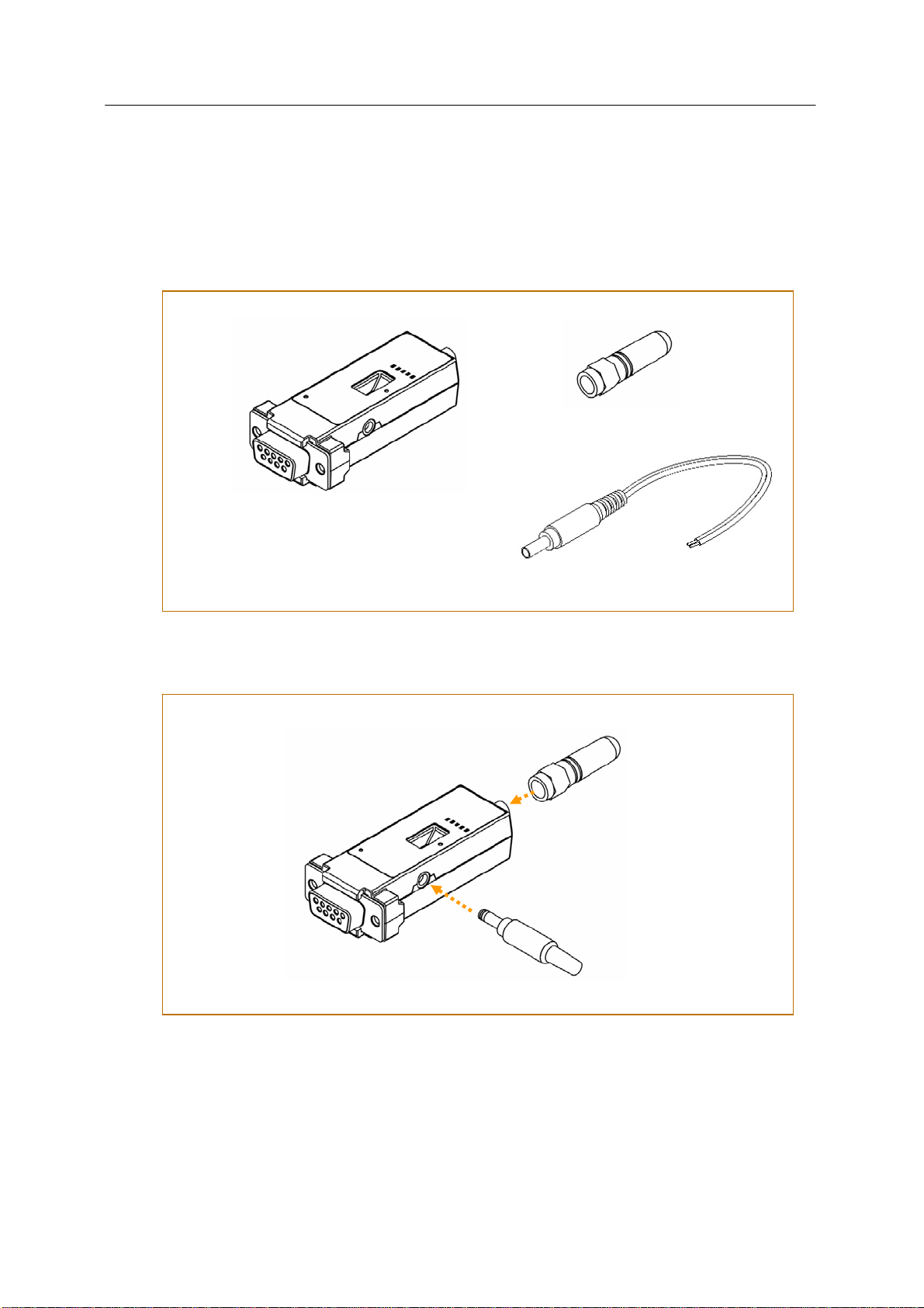
Promi SD205-OA User Manual – 2. Configurations 7
Operation Modes
In addition to the serial port configurations such as bit/second, data bit, parity, stop bit, flow control, Promi SD205-OA
has some configurations for Bluetooth. For getting the most out of Promi SD205-OA, user should understand the
following Bluetooth connection schemes.
A Bluetooth device can play a role as a master or slave. Master tries to connect itself to other Bluetooth device, and
slave is waiting to be connected from other Bluetooth devices. A Bluetooth connection is always made by a pair of
master and slave. A slave can be in two modes, Inquiry Scan or Page Scan mode. Inquiry Scan mode is waiting the
packet of inquiry from other Bluetooth devices and Page Scan mode is waiting the packet of connection from other
Bluetooth devices. Every Bluetooth device has its unique address, called BD (Bluetooth Device) address, which is
composed of 12 hexa-decimal numbers.
Promi SD205-OA has 4 operation modes as follows. Each mode can be identified with LED indicators as illustrated in
next section.
ÌMode0
Promi SD205-OA must be in Mode0, when it is directly controlled by AT commands.
In this mode, there is no response when power on or software reset, and Promi SD205-OA is just waiting for AT command
input. Neither master nor slave is assigned to Promi SD205-OA in mode0. User can change the configurations of Promi
SD205-OA in this mode.
The factory default is set to Mode0.
ÌMode1
Promi SD205-OA tries to connect the last connected Bluetooth device.
Promi SD205-OA in Mode1 is to be a master and tries to connect the last connected Bluetooth device. Promi SD205-OA
always stores the BD address of the Bluetooth device to which Promi SD205-OA has connected last time. When Promi
SD205-OA is initially used or after hardware reset, there is no BD address stored in Promi SD205-OA. In this case, Mode1
does not make any sense and mode change from other operation modes to Mode1 is not allowed. The mode change
to Mode1 can be made after Promi SD205-OA succeeds to connect to other Bluetooth device in Mode0. Once
changed to Mode1, Promi SD205-OA will try to connect automatically the last connected Bluetooth device whenever
power on or software reset.
Promi SD205-OA in Mode1 cannot be discovered or connected by other Bluetooth devices.
ÌMode2
Promi SD205-OA is waiting for the connection from the last connected Bluetooth device.
Promi SD205-OA in Mode2 is to be a slave and waiting for the connection only from the last connected Bluetooth
device. Just like Mode1, if there is no BD address stored in Promi SD205-OA, the mode change from other operation
modes to Mode2 is not allowed. Once changed to Mode2, Promi SD205-OA will wait for the connection from the last
connected Bluetooth device whenever power on or software reset.
Promi SD205-OA in Mode2 cannot be discovered or connected to Bluetooth devices other than the last connected
device.
ÌMode3
Promi SD205-OA is waiting for the connection from any other Bluetooth devices.
Promi SD205-OA in Mode3 acts like in Mode2, but allows any connection from other Bluetooth device. Most of general
Bluetooth device is set to Mode3.
Promi SD205-OA in Mode3 can be discovered and connected from any other Bluetooth devices.

Promi SD205-OA User Manual – 2. Configurations 8
LED Indicators
Indicator Power LED Standby LED Connect LED
Mode0 Green ┏━━━━━━━ Red ┏━━━━━━━
Mode1 Green ┏━━━━━━━ Green (every 1 sec) ┏┓
Mode2 Green ┏━━━━━━━ Green (every 3 sec) ┏┰┓
Mode3 Green ┏━━━━━━━ Green (every 3 sec) ┏┰┓
Connected Green ┏━━━━━━━ Green ┏━━━━━━━
RS232-Tx and RS232-Rx LED are blinking accordingly when data is transmitted. For small data transmission, it may be
hard to recognize the quick blinking.
Serial Ports
The applicable settings for serial ports are as follows.
Serial Port Settings Values
Baud rate 1200, 2400, 4800, 9600 , 19200, 38400, 57600, 115200, 230400
Data bit 8
Parity No parity , Even parity, Odd parity
Stop bit 1 , 2
The values in box are the factory defaults.
ÌData Bit
Promi SD205-OA supports only 8 data bit. In the case of 7 data bit, please contact the technical support.
ÌHardware Flow Control
Promi SD205-OA plugged into its host system transmits data from host to the other side Bluetooth device. These data is
saved temporarily in the internal buffer of Promi SD205-OA and sent repeatedly until the transmission is completed
packet by packet. When the radio transmission condition is not good enough to send data promptly, it can cause the
transmission delay. If the host sends more data when the buffer is full, buffer overflow will make Promi SD205-OA
malfunction consequently. In order to prevent this buffer overflow, Promi SD205-OA works as follows.
Promi SD205-OA is always not not using hardware flow control, Promi SD205-OA clears the buffer to secure the room for
next data when the buffer becomes full. This means the loss of data. As the transmission data becomes large, the
possibility of data loss goes higher.
Reset to Factory Defaults
To turn back all the configurations to its factory settings, press the reset button depicted in Fig. 1-3. Press the reset
button with a narrow pointed tool like paper clip longer than 1 second. Reset works only when power is on.
Terminal Program

Promi SD205-OA User Manual – 2. Configurations 9
A terminal Tprogram is an application that will enable a PC to Tcommunicate directly with a modem. If you are using
Windows 98SE or higher version of Windows, HyperTerminal program as it is included as part of the operating system.
Promi SD205-OA provides some extended AT commands for its configurations on terminal program.
This manual will explain the method using HyperTerminal. If you need to install HyperTerminal, click start>setting>control
panel>add/remove programs. For more precise information, please refer to Help of Microsoft Windows.
Attach Promi SD205-OA to serial port of host computer and power on. Standby LED is lit in green.
Launch HyperTerminal. It can be found in start >programs >accessories >communication >HyperTerminal. Select the
Serial port that Promi SD205-OA will be connected to.
Input the same settings into Serial port configuration window as Promi SD205-OA settings.
The settings need to be set correctly, otherwise, error message may be shown up on the screen or cause
malfunctioning of Promi SD205-OA.
Choose the settings in File->Properties->Settings->ASCII setup that let you turn echo on in HyperTerminal; this will show
the response Promi SD205-OA sends on the screen.
You now get the HyperTerminal window where you are able to control Promi SD205-OA with AT commands. For
expanded AT commands that Promi SD205-OA provides, please refer to Appendix A. AT commands.
Example of AT commands:
Dip Switch
With the combination of 4 slot dip switches, baud rate and hardware flow control can be set simply without host
computer.
Upper 3 dip switches are used for setting baud rate, and bottom dip switch is used for setting hardware flow control
option. If the baud rate needs to be set out of the range given below, PromiWIN or terminal program should be used
for extended AT commands. At this time combination of dip switches must be complied with AT cmd. Then baud rate
will go back to 9600 as default.
AT+BTINFO?
000195000509,PSDv3b-000509,MODE0,STANDBY,0,0,HWFC
OK
AT+BTINQ?
00019520007E,PSDv2a-20007E,001F00
0004B300E205,AP2002:1 #0,020300
OK
ATD00019520007E
OK
CONNECT 0001952007E
Pairing Button
Dip Switch
Reset Button

Promi SD205-OA User Manual – 2. Configurations 10
2400 4800 9600 19.2K 38.4K 57.6K 115.2K AT cmdBaud
Rate
Pairing Button
Promi SD205-OA provides Pairing Button for instant configuration without PC to make an automatic connection
between two Promi SD205-OAs. For convenience sake, name two Promi SD205-OAs as SD1 and SD2 respectively.
1. Turn off all the nearby Promi SD205-OA
2. Turn on SD1 and SD2 and hardware reset both of them by pressing Reset Button.
3. Press the Pairing Button of SD1 for 2 seconds until Standby LED turns off and Connect LED blinks 3 times every
2 seconds. Keep the power ON.
4. Press the Pairing Button of SD2 for 2 seconds until Standby LED turns off and Connect LED blinks 3 times every
2 seconds. Now press again the Pairing Button for 2 seconds until Connect LED blinks every 0.5 second.
5. Wait for SD1 & SD2 to be connected for a while until Connect LED’s of SD1 and SD2 is lit in green. It takes
about 10 seconds to make a connection. If there are many Bluetooth devices nearby, it will take a little bit
more.
6. Turn SD1 off and on. Connect LED blinks twice in green every 3 seconds.
7. Turn SD2 off and on. Connect LED blinks once in green every 1 second.
8. Now a pair of Promi SD205-OA is configured to make automatic connection, whenever power off and on.
9. Just use this pair of Promi SD205-OA like virtual serial cable.
SD 1 status LED SD 2 status LED
1. hard reset Mode0 Standby LED turn on. 1. hard reset Mode0 Standby LED turn on.
2. push pairing
button Mode3 Connect LED blinks 3
times every 2 sec. 2. push pairing
button Mode3 Connect LED blinks 3
times every 2 sec.
3. 3. push pairing
button agian Mode1 Connect LED blinks every
0.5 sec.
4. connected Slave Connect LED is lit in
green 4. connected Master Connect LED is lit in
green

Promi SD205-OA User Manual – 3. Connections 11
3. Connections
zRS232 Interface
zPin Assignment
zPower Supply

Promi SD205-OA User Manual – 3. Connections 12
RS232C Interface
ÌDTE/DCE
If the full EIA232 standard is implemented as defined, the equipment at the far end of the connection is named the DTE
device (Data Terminal Equipment, usually a computer or terminal), has a male DB9 connector. Equipment at the near
end of the connection (the telephone line interface) is named the DCE device (Data Circuit-terminating Equipment,
usually a modem), has a female DB9 connector. The cable linking DTE and DCE devices is a parallel straight-through
cable with no cross-overs or self-connects in the connector hoods. If all devices exactly followed this standard, all
cables would be identical, and there would be no chance that an incorrectly wired cable could be used.
ÌDB9 Female
Promi SD205-OA is a DCE device compatible with RS232 standard, having DB9 female interface.
Pin # Signal Direction Description
1 N/A
2 RxD Input
Received Data
3 TxD Output
Transmitted Data
4 N/A
5 N/A
6 Vcc Input
5V~12V
7 N/A
8 N/A
9 GND Signal Ground

Promi SD205-OA User Manual – 3. Connections 13
Pin Assignment
ÌPromi SD205-OA must be use for connect pc to Promi SD205-OA connection cable.

Promi SD205-OA User Manual – 3. Connections 14
Power Supply
Promi SD205-OA can be supplied power through the power jack and through pin 6 of DB9 connector.
ÌThrough Power Jack
DC 5 ~ 12V, Min. 150mA power should be supplied through DC power cable. Red cable is positive and black one is
negative.
AC/DC power adaptor and USB power cable are also available to supply power.
ÌThrough Pin 6 of DB9 connector
The power can be supplied through pin 6 of DB9 connector. Because Promi SD205-OA does not have any protection
circuit from surge
Electrical Polarity
DC Power Cable
AC/DC Power Adapter USB Power Cable
Red +
Black -

Promi SD205-OA User Manual – 4. Specifications 15
4. Specifications
zBluetooth
zSerial Interface
zPower
zMechanical Dimensions
zEnvironmental
zDefault Antenna
zWireless Coverage

Promi SD205-OA User Manual – 4. Specifications 16
ÌBluetooth Interface
yBluetooth 1.2 specification compatible and qualified
yProtocol: RFCOMM, L2CAP, SDP
yProfiles: Serial Port Profile, Generic Access Profile, Service Discovery Profile
yRadio Frequency: 2.402 ~ 2.480GHz
yNumber of Channels: 79
yTransmission Power Class 1
yData Transmission Rate: 380Kbps Max.
ÌSerial Interface
yEIA RS232C Standard
yConnector: DB9 female
yData Transmission Rate: 1,200 ~ 230,400bps
yHardware Flow Control: Not Support
ÌPower
yDC 5 V Constant Voltage
ySupply: DC Jack or Pin 6 of DB9
ÌMechanical Dimensions
ÌEnvironmental
yRecommended Operational Temperature: -20℃~ 55℃
yRecommended Operational Humidity: 90% Max. Non-condensing
63mm 35mm
16mm
30mm

Promi SD205-OA User Manual – 4. Specifications 17
ÌDefault Antenna
yType: Helical
yFrequency: 2,400 ~ 2,485GHz
yGain: Max. 2dBi
yImpedance: 50Ω
ysize: 30mm¯9mm (W¯D)
yweight: 3.5g
ÌWireless Coverage
The table below shows the average measuring results in open space. These results can vary according to the
environmental conditions.
Antennas for two Promi SD205-
OA units Maximum Distance
Helical Antenna 100 m

Promi SD205-OA User Manual – Appendix A. AT Commands A-1
Appendix A. AT Commands
zTerminology
zCommand Description
Table of contents
Other Sena Receiver manuals